

Page 1
1 4 2 5 6
3
POLSO
POLSO L
Installation&Maintenance Instructions
Montaj&Bakım Kılavuzu
1.
2. A B B E D C
E
LUMINAIRE
CODE
A
B
C
D
E
LB6052.509
19 11/16
19 11/16
MIN 2 53/64
13 25/32
9 27/32
LB6053.509
19 11/16
25 5/8
MIN 2 53/64
13 25/32
9 27/32
4 M12 / M16 Nuts
8X M12 / M16 Nuts
4X M12 / M16 Washers
HEPER USA LLC
W227 N546 Westmound
Drive Waukesha
WI 53186 – USA
Tel: +1 917 244 20 32
[email protected]
www.heperlighting.com
2020-0/01.09.2020
Inch
For M12 - S19 59 lb ft
For M16 – S24 132 lb ft
Inch
Inch
Inch
Inch
1.1 lb ft
Page 2
7 8 9
11
10
12
1.
2.
2xM4 Flat Head Screws
S5
15
14
13
3xM5 Set Screws
S2.5
2xM5 Head Bolts
S8
6xM10 Head Bolts
1.1 lb ft
1.1 lb ft
1.1 lb ft
3.6lb ft
2.9lb ft
18 lb ft
Page 3
A
B
C
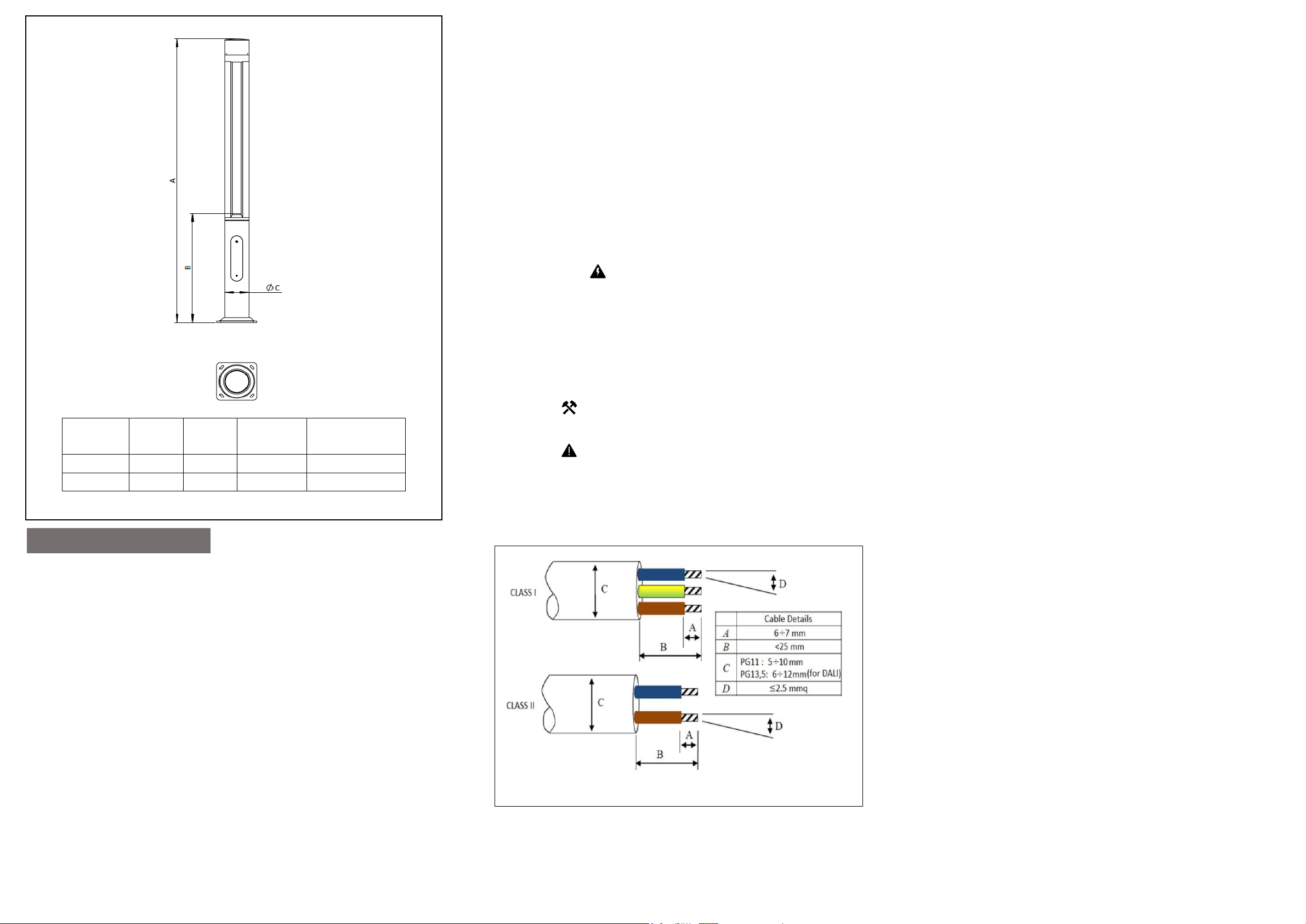
10. Detaching the LED driver from the cartridge assembly;
10.1.Cables from LED driver to fuses and terminals are removed
10.2.The bolts holding the LED driver are removed. The LED driver is detached.
Note1: While installing the LED driver, the bolts are tightened with 1.1 lb ft torque.
Note2: Make sure that the LED driver is not damaged and that it fits well when
installing.
To reach the lighting module;
11. Module cover cap fixing bolts are removed. (3 Pieces, M5 Setscrew Bolt)
Note: During the remounting bolts are fixed with a torque of 2.9 lb ft
12.The module cover is removed.
13. LED lighting module socket is removed.
14. The LED module is carefully removed. When mounting the LED module, care must be
taken to ensure that the socket (resistant to water and dust) that provides electricity
transmission is not damaged and is fully seated. (6 Pieces, M10 Head Bolt)
Note1: When installing the LED module, check whether the tab on the side is in
place.
Note2: While the LEDmodule is being installed, its bolts are tightened with a
torque of 18lb ft.
15. LED module view.
WARNINGS AND REMARKS FOR INSTALLATION
AND MAINTENANCE
Safety Instructions
• The light source contained in this luminaire shall only be replaced by the manufacturer or his
service agent or a similar qualified person. Always switch off the power prior to installation,
maintenance or repair activities.
• The manufacturer is then discharged from liability when damage is caused by improper use or
installation.
•
If any luminaire is subsequently modified, the persons responsible for the modification shall be
considered as manufacturer.
To reduce the risk of death, personal injury or property damage from fire, electric shock, falling
•
parts, cuts, abrasions and other hazards, please read all warnings and instructions included
with the luminaire, on the luminaire’s packaging and affixed to the luminaire itself..
(Inch)
8'
13'
WEIGHT
(Inch)
37 51/64 7 7/8 67.88
58 21/32
(Inch)
7 7/8 89.59
(lb)
LUMINAIRE
CODE
LB6052.509
LB6053.509
English
ASSEMBLY INSTRUCTIONS
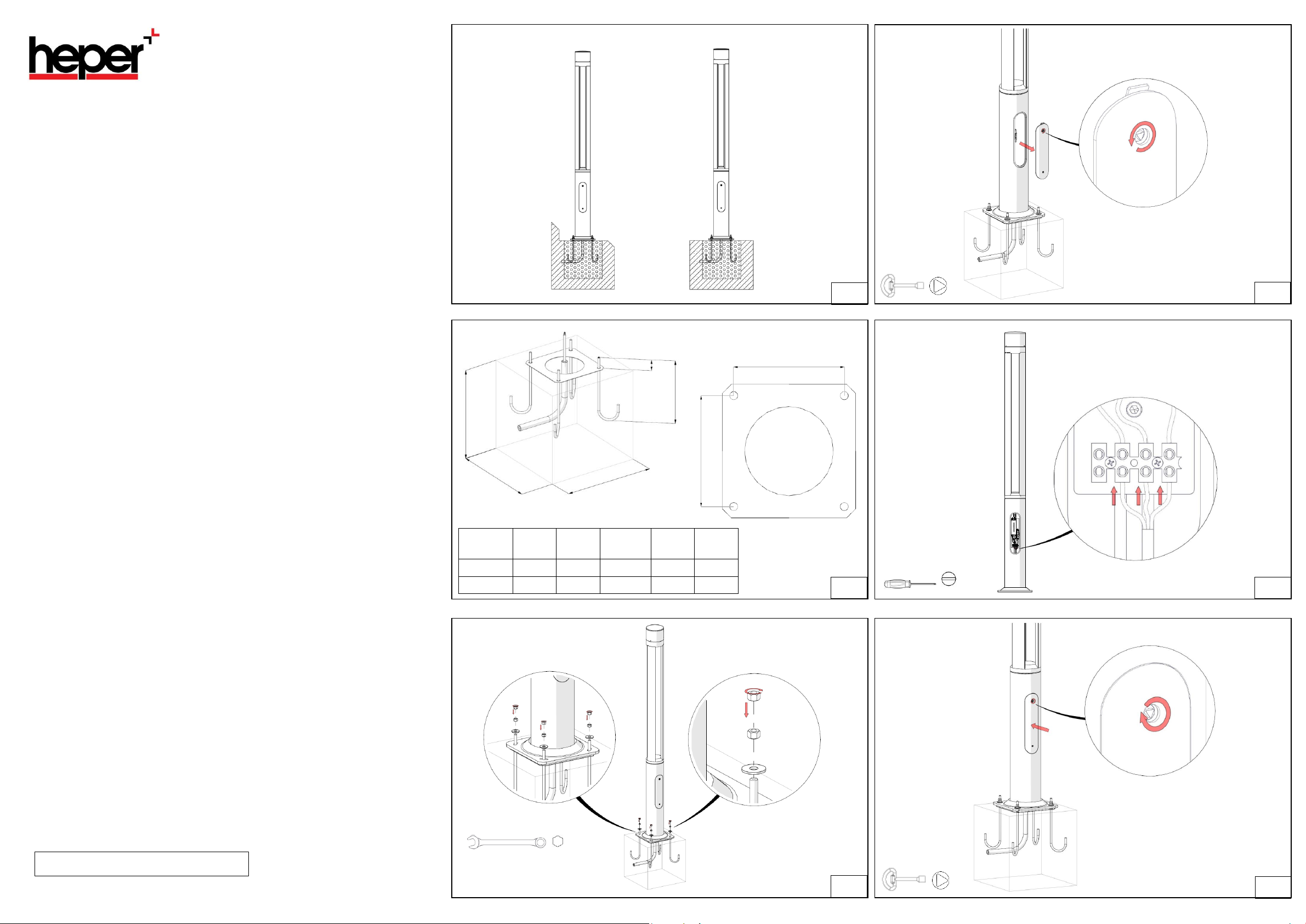
To mount the product on the floor;
1.The floor on which the product will be installed must be flat.
2.The space on the floor is adjusted according to the given concrete dimensions
2.1.A template plate is used to align the connection holes of the product. (Hole Center: 9
27⁄32")
2.2.Anchor studs are embedded in concrete using the template plate, with a minimum
height of 2 53⁄64"
plate for alignment is removed.
2.3.Adjustment nuts are attached to the anchorage studs. (4 Pieces, M12 Nuts or 4 Pieces,
M16 Nuts)
3.After the base flange is placed, the nuts are tightened with 29.5lb ft torque by placing
flat washers under them, and turn one nut each into the skid. (8 Pieces, M12 Nuts or 8
Pieces, M16 Nuts)
4.The fuse cover is removed by loosening the triangular headed bolt.
5.Cables supplying electrical current to the product are fixed to the terminals with 1.1 lb
ft torque.
6.The triangular headed bolt is tightened by mounting the fuse cover. Make sure that the
fuse cover fits properly.
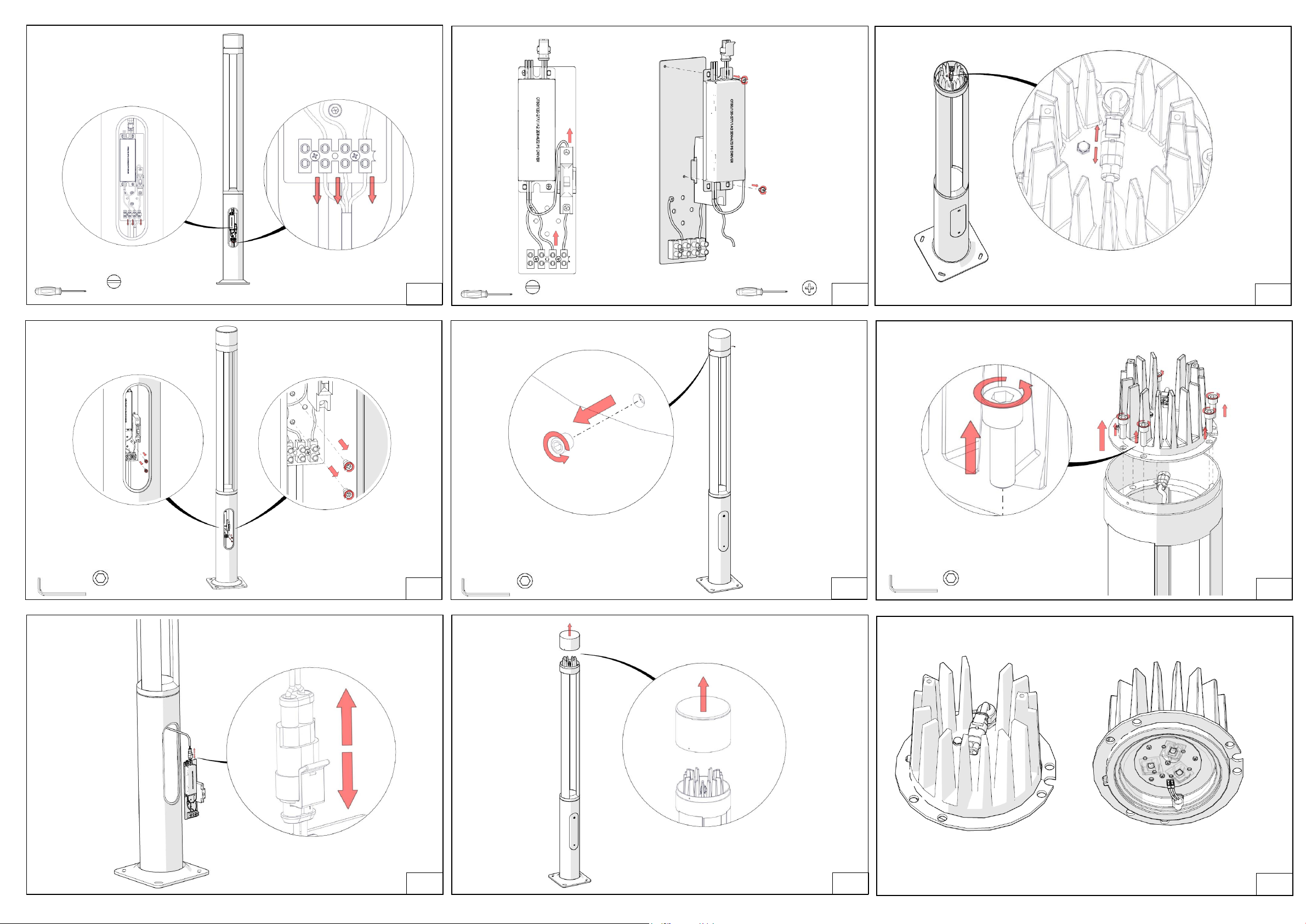
To reach the LED driver;
Note: The electrical connection to the product must be disconnected before starting this
process.
7.To access the LED driver, the fuse cover is opened by following step 4. The terminal
cable connections in the image are removed.
9.Cartridge group is taken out. LED driver sockets are removed. The cartridge group is
separated.
Note:Once the studs are fixed and the concrete has been poured, the anchor
Note: Cable connections can be made by following step 5.
8. Bolts that hold the cartridge group are removed. (2 Pieces, M5 Head Bolt)
Note: The cartridge is fixed with a torque of 3.6lb ft during assembly.
Note: Be careful not to damage the LED driver and sockets.
Installatio n
•
LEDs are high-quality electronic components! Please avoid contacting the light output opening
of the LED directly during installation or relamping.
IMPORTANT
•
To ensure secure connection, the luminaire housing must be positioned precisely in relation to
the mounting plate.
Cleaning And Maintenance
• Clean luminaire regularly with solvent-free cleaners from dirt. Please do not do not clean the
luminaire with using high-pressure liquids.
 Loading...