

Page 1

REGISTER WARRANTY ONLINE AT WWW.HENNYPENNY.COM
Model OFE/OFG-321
Model OFE/OFG-322
Model OFE/OFG-323
Model OFE/OFG-324
Model OEA/OGA-321
Model OEA/OGA-322
Model OEA/OGA-323
Model OEA/OGA-324
Model ODE/ODG-323
Henny Penny
Open Fryer
(Full & Split Vat)
’
Page 2

Page 3

Model OFE/OFG-321,322,323,324
LIMITED WARRANTY FOR HENNY PENNY EQUIPMENT
Subject to the following conditions, Henny Penny Corporation makes the following limited warranties to the original
purchaser only for Henny Penny appliances and replacement parts:
NEW EQUIPMENT:
in material or workmanship within two (2) years from date of original installation, will be repaired or replaced
without charge F.O.B. factory, Eaton, Ohio, or F.O.B. authorized distributor. Baskets will be repaired or replaced
for ninety (90) days from date of original installation. Lamps and fuses are not covered under this Limited
Warranty. To validate this warranty, the registration card for the appliance must be mailed to Henny Penny within
ten (10) days after installation.
FILTER SYSTEM
other unapproved filters is not
REPLACEMENT PARTS:
in material or workmanship within ninety (90) days from date of original installation will be repaired or replaced
without charge F.O.B. factory, Eaton, Ohio, or F.O.B. authorized distributor.
The warranty for new equipment covers the repair or replacement of the defective part and includes labor charges and
maximum mileage charges of 200 miles round trip for a period of one (1) year from the date of original installation.
The warranty for replacement parts covers only the repair or replacement of the defective part and does not include any
labor charges for the removal and installation of any parts, travel, or other expenses incidental to the repair or replacement of
a part.
EXTENDED FRYPOT WARRANTY:
workmanship issues for a period of up to seven (7) years from date of manufacture. This warranty shall not cover any frypot
that fails due to any misuse or abuse, such as heating of the frypot without shortening.
0 TO 3 YEARS:
will be replaced at no charge for parts, labor, or freight. Henny Penny will either install a new frypot at no
cost or provide a new or reconditioned replacement fryer at no cost.
3 TO 7 YEARS:
will be replaced at no charge for the frypot only. Any freight charges and labor costs to install the new
frypot as well as the cost of any other parts replaced, such as insulation, thermal sensors, high limits,
fittings, and hardware, will be the responsibility of the owner.
Any claim must be presented to either Henny Penny or the distributor from whom the appliance was purchased. No
allowance will be granted for repairs made by anyone else without Henny Penny’s written consent. If damage occurs during
shipping, notify the sender at once so that a claim may be filed.
THE ABOVE LIMITED WARRANTY SETS FORTH THE SOLE REMEDY AGAINST HENNY PENNY FOR ANY
BREACH OF WARRANTY OR OTHER TERM. BUYER AGREES THAT NO OTHER REMEDY (INCLUDING
CLAIMS FOR ANY INCIDENTAL OR CONSEQUENTIAL DAMAGES) SHALL BE AVAILABLE.
The above limited warranty does not apply (a) to damage resulting from accident, alteration, misuse, or abuse; (b) if the
equipment’s serial number is removed or defaced; or (c) for lamps and fuses. THE ABOVE LIMITED WARRANTY IS
EXPRESSLY IN LIEU OF ALL OTHER WARRANTIES, EXPRESS OR IMPLIED, INCLUDING MERCHANTABILITY
AND FITNESS, AND ALL OTHER WARRANTIES ARE EXCLUDED. HENNY PENNY NEITHER ASSUMES NOR
AUTHORIZES ANY PERSON TO ASSUME FOR IT ANY OTHER OBLIGATION OR LIABILITY.
Any part of a new appliance, except baskets, lamps, and fuses, which proves to be defective
: Failure of any parts within a fryer filter system caused by the use of the non-OEM filters or
covered under this Limited Warranty.
Any appliance replacement part, except lamps and fuses, which proves to be defective
Henny Penny will replace any frypot that fails due to manufacturing or
During this time, any frypot that fails due to manufacturing or workmanship issues
During this time, any frypot that fails due to manufacturing or workmanship issues
Revised 01/01/07
.
FM05-012-J
Revised 2-11-11
Page 4
Model OFE/OFG-321,322,323,324
This manual should be retained in a convenient location for future reference.
A wiring diagram for this appliance is located on the inside of the right side panel.
Post in a prominent location, instructions to be followed in event user smells gas. This information shall
be obtained by consulting the local gas supplier.
Do not obstruct the flow of combustion and ventilation air. Adequate clearance must be left all around
appliance for sufficient air to the combustion chamber.
The Model OFG/OGA-32X open fryer is equipped with a continuous pilot. But the open fryer cannot be
operated without electric power. The unit will automatically return to normal operation when power is
restored.
To avoid a fire, keep appliance area free and clear from combustibles.
Improper installation, adjustment, alteration, service, or maintenance can cause property damage,
injury, or death. Read the installation, operating, and maintenance instructions thoroughly before
installing or servicing this equipment.
DO NOT STORE OR USE GASOLINE OR OTHER FLAMMABLE VAPORS
AND LIQUIDS IN THE VICINITY OF THIS OR ANY OTHER APPLIANCE. FIRE OR
EXPLOSION COULD RESULT.
Page 5

Model OFE/OFG-321,322,323,324
Technical Data for CE/AGA Marked Products
Nominal Heat Input: Natural (I2H) = 24.9 KW (85,000 Btu/h)
(Net) Natural (I
Natural (I
Natural (I2L) = 24.9 KW (85,000 Btu/h)
Liquid Propane (I
Nominal Heat Input: Natural (I
(Gross) Natural (I2E) = 27.7 KW (94,500 Btu/h)
Natural (I2E+) = 27.7 KW (94,500 Btu/h)
Natural (I2L) = 27.7 KW (94,500 Btu/h)
Liquid Propane (I
Supply Pressure: Natural (I
Natural (I
Natural (I
Natural (I2L) = 25 mbar
Liquid Propane (I3P) = 30 mbar
Liquid Propane (I3P) = 37 mbar (3.7 kPa)
Liquid Propane (I3P) = 50 mbar (5.0 kPa)
Test Point Pressure: Natural (I2H) = 8.7 mbar (0.87 kPa)
Natural (I2E) = 8.7 mbar
Natural (I2E+) = 8.7/10 mbar
Natural (I2L) = 10 mbar
Liquid Propane (I3P) = 24.5 mbar (2.5 kPa)
Injector Size: Natural (I
Natural (I
Natural (I
Natural (I
Liquid Propane (I
Restrictor Size: Natural (I
This appliance must be installed in accordance with the manufacturer’s instructions and the regulations
in force and only used in a suitably ventilated location. Read the instructions fully before installing or
using the appliance.
) = 24.9 KW (85,000 Btu/h)
2E
+) = 24.9 KW (85,000 Btu/h)
2E
) = 24.9 KW (85,000 Btu/h)
3P
) = 27.7 KW (99.70 MJ/h) (94,500 Btu/h)
2H
) = 27.7 KW (99.70 MJ/h) (94,500 Btu/h)
3P
) = 20 mbar (2.0 kPa)
2H
) = 20 mbar
2E
+) = 20/25 mbar
2E
) = 3.26 mm
2H
) = 3.26 mm
2E
+) = 3.26 mm
2E
) = 3.26 mm
2L
) = 1.93 mm
3P
+) = 4.6 mm
2E
Page 6

Model OFE/OFG-321,322,323,324
TABLE OF CONTENTS
Section Page
Section 1. INTRODUCTION ............................................................................................................1-1
1-1. Introduction .............................................................................................................1-1
1-2. Features ...................................................................................................................1-1
1-3. Proper Care .............................................................................................................1-1
1-4. Assistance ...............................................................................................................1-1
1-5. Safety ......................................................................................................................1-2
Section 2. INSTALLATION .............................................................................................................2-1
2-1. Introduction .............................................................................................................2-1
2-2. Unpacking ............................................................................................................... 2-1
2-3. Selecting the Location ............................................................................................2-2
2-4. Leveling the Open Fryer .........................................................................................2-2
2-5. Ventilation of Open Fryer .......................................................................................2-2
2-6. Gas Supply ..............................................................................................................2-3
2-7. Gas Leak Test .........................................................................................................2-6
2-8. Gas Pressure Regulator Setting ...............................................................................2-6
2-9. Electrical Requirements OFG-320 Series ...............................................................2-6
2-10. Electrical Requirements OFE-320 Series ...............................................................2-7
2-11. Testing the Fryer .....................................................................................................2-8
2-12. Joining Instructions .................................................................................................2-8
Section 3. OPERATION ....................................................................................................................3-1
3-1. Operating Components C1000 Controls .................................................................3-1
3-2. Operating Components 6 & 12 Button Controls ....................................................3-3
3-3. Clock Set .................................................................................................................3-7
3-4. Filling or Adding Shortening ..................................................................................3-9
3-5. C1000 Operations and Procedures ..........................................................................3-10
3-6. C1000 Programming Instructions ...........................................................................3-11
3-7. C1000 Special Programming ..................................................................................3-12
3-8. Basic Operations and Procedures (6 Product Controls)..........................................3-13
3-9. Basic Operations and Procedures (12 Product Controls/Auto-Lift) .......................3-15
3-10. Care of Shortening ..................................................................................................3-17
3-11. Filtering of Shortening ............................................................................................3-18
3-12. Filter Pump Problem Prevention .............................................................................3-22
3-13. Filter Pump Motor Protector - Manual Reset .........................................................3-22
3-14. Changing the Filter Envelope .................................................................................3-22
3-15. Cleaning the Frypot ................................................................................................3-24
3-16. Clean-Out Mode .....................................................................................................2-25
3-17. Operating Instructions for Optional Direct-Connect Shortening System ...............3-26
3-18. Lighting and Shutdown of the Burners ...................................................................3-27
3-19. High Temperature Limit Control ............................................................................3-28
3-20. Regular Maintenance ..............................................................................................3-28
i 211
Page 7

Model OFE/OFG-321,322,323,324
TABLE OF CONTENTS
Section Page
Section 4. PROGRAMMING – 6 & 12 PRODUCT CONTROLS ..................................................4-1
4-1. Introduction .............................................................................................................4-1
4-2. Product Program Mode ...........................................................................................4-1
4-3. Special Program Mode ............................................................................................4-4
4-4. Data Logging, Heat Control, Tech, and Stat Modes ...............................................4-15
Section 5. TROUBLESHOOTING ...................................................................................................5-1
5-1. Troubleshooting Guide ...........................................................................................5-1
5-2. Error Codes .............................................................................................................5-2
Section 6. INFORMATION MODE .................................................................................................6-1
GLOSSARY ....................................................................................................................G-1
Distributors List - Domestic and International
308 i
Page 8

Model OFE/OFG-321,322,323,324
SECTION 1. INTRODUCTION
1-1. INTRODUCTION The Henny Penny Open Fryer is a basic unit of food
equipment designed to cook foods better and easier. The
microcomputer-based design helps make this possible. This
unit is used only in institutional and commercial food service
operations.
As of August 16, 2005, the Waste Electrical and
Electronic Equipment directive went into effect for the
European Union. Our products have been evaluated to
the WEEE directive. We have also reviewed our
products to determine if they comply with the
Restriction of Hazardous Substances directive (RoHS)
and have redesigned our products as needed in order to
comply. To continue compliance with these directives,
this unit must not be disposed as unsorted municipal
waste. For proper disposal, please contact your nearest
Henny Penny distributor.
1-2. FEATURES • Easily cleaned
• Full frypot 65 lbs. (29.5 kg.) shortening capacity
• Split frypot 25 lbs. (11.3 kg.) shortening cap. (elec. only)
• 2 Half size baskets per well (or full size baskets)
• Stainless steel construction
• Manual reset high limit control
• Self-diagnostic system built into controls
• Built in filter (handles all 3 wells)
• Propane or natural gas; 85,000 btu/pot (26.38 kw)
• Energy Save Mode upon activation for gas fryers
• Many combinations of split frypot/full frypot fryers
• Simplistic electronic Computron 1000 controls available,
or more diverse multifunctional controls available
1-3. PROPER CARE As in any unit of food servicing equipment, the open fryer
does require care and maintenance. Requirements for the
maintenance and cleaning are contained in this manual and
must become a regular part of the operation of the unit at all
times.
1-4. ASSISTANCE
1-1 108
Should you require outside assistance, call your local
independent Henny Penny distributor in your area, call
Henny Penny Corp. at 1-800-417-8405 or 1-937-456-8405,
or go to Henny Penny online at www.hennypenny.com.
Page 9

Model OFE/OFG-321,322,323,324
1-5. SAFETY The Henny Penny Open Fryer has many safety features
incorporated. However, the only way to ensure safe
operation is to fully understand the proper installation,
operation, and maintenance procedures. The instructions in
this manual have been prepared to aid you in learning the
proper procedures. Where information is of particular
importance or is safety related, the words DANGER,
WARNING, CAUTION, or NOTE are used. Their usage is
described on the next page:
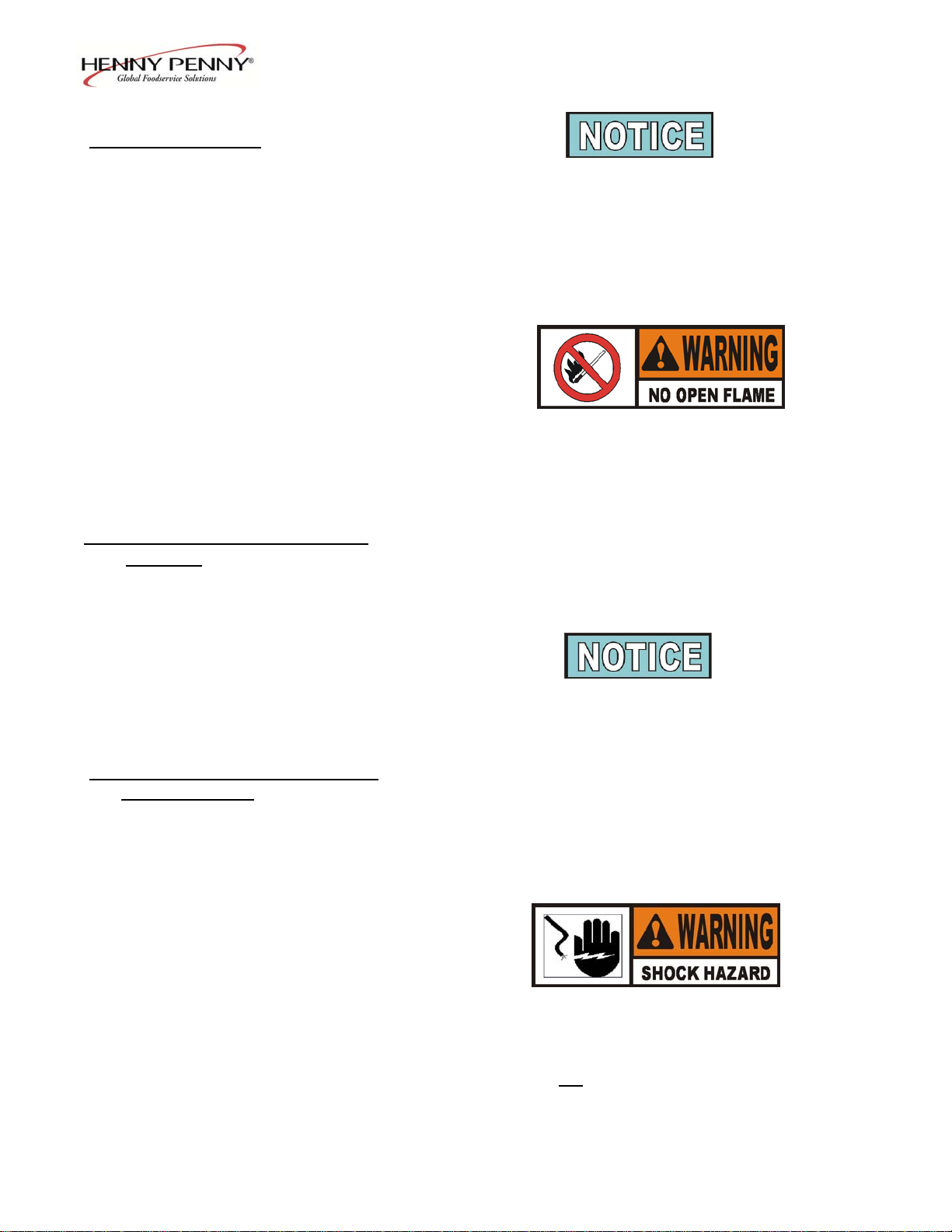
SAFETY ALERT SYMBOL is used with
DANGER, WARNING or CAUTION which
indicates a personal injury type hazard.
NOTICE is used to highlight especially important
information.
CAUTION used without the safety alert symbol indicates
a potentially hazardous situation which, if not avoided,
may result in property damage.
CAUTION used with the safety alert symbol indicates a
potentially hazardous situation which, if not avoided,
could result in minor or moderate injury.
WARNING indicates a potentially hazardous
situation which, if not avoided, could result in death
or serious injury.
DANGER INDICATES AN IMMINENTLY
HAZARDOUS SITUATION WHICH, IF NOT
AVOIDED, WILL RESULT IN DEATH OR
SERIOUS INJURY.
703 1-2
Page 10
Model OFE/OFG-321,322,323,324
SECTION 2. INSTALLATION
2-1. INTRODUCTION This section provides the installation instructions for
the Henny Penny Open Fryer.
Installation of the unit should be performed only by a
qualified service technician.
Do not puncture the unit with any objects such as
drills or screws as component damage or electrical
shock could result.
2-2. UNPACKING The Henny Penny Open Fryer has been tested, inspected, and
expertly packed to ensure arrival at its destination in the best
possible condition. The unit is banded to a wooden skid and
then packed inside a heavy cardboard carton with sufficient
padding to withstand normal shipping treatment.
Any shipping damage should be noted in the presence
of the delivery agent and signed prior to his or her
departure.
1. Carefully cut bands from cardboard carton.
2. Lift carton from the unit.
3. Cut and remove the metal bands holding the fryer to the
pallet.
4. Remove the fryer from the pallet.
Take care when moving the fryer to prevent
personal injury. The fryer can weigh between
305 lbs. (138 kg) and 616 lbs. (279 kg).
2-1 703
Page 11
Model OFE/OFG-321,322,323,324
2-3. SELECTING THE The proper location of the open fryer is very important for
LOCATION the duration, speed, and convenience. The location of the
open fryer should allow clearances for servicing and proper
operation. Choose a location which will provide easy
loading and unloading without interfering with the final
assembly of food orders. Operators have found that frying
from raw to finish, and holding the product in warmers
provides fast continuous service. Keep in mind, the best
efficiency will be obtained by a straight line operation, i.e.,
raw in one side and finished out the other side. Order
assembly can be moved away with only a slight loss of
efficiency.
To prevent severe burns from splashing hot
shortening, position and install fryer to prevent
tipping or movement. Restraining ties may be used
for stabilization.
To avoid fire, install the open fryer with minimum
clearance from all combustible and noncombustible
materials, 4 inches (10.16 cm) from the side and 4
inches (10.16 cm) from the back. If installed properly,
the open fryer is designed for operation on combustible
floors and adjacent to combustible walls.
Do not spray aerosols in the vicinity of this appliance
while it is in operation.
2-4. LEVELING THE OPEN For proper operation, the open fryer should be level from
FRYER
side to side and front to back. Using a level placed on the
flat areas around the frypot collar, on the middle well, adjust
the casters until the unit is level.
2-5. VENTILATION OF OPEN The open fryer should be located with provision for venting
FRYER
into an adequate exhaust hood or ventilation system. This is
essential to permit efficient removal of the steam exhaust and
frying odors. Special precaution must be taken in designing
an exhaust canopy to avoid interference with the operation of
the open fryer. We recommend you consult a local
ventilation or heating company to help in designing an
adequate system.
211 2-2
Page 12
Model OFE/OFG-321,322,323,324
2-5. VENTILATION OF OPEN
FRYER
(Continued)
Ventilation must conform to local, state, and national
codes. Consult your local fire department or building
authorities.
When installing the gas open fryer, do not attach an
extension to the gas flue exhaust stack. This may impair
proper operation of the burner, causing malfunctions
and possible negative back draft.
2-6. GAS SUPPLY
cabinet to determine the proper gas supply requirements. The
minimum supply for natural gas is 7 inches water column
(1.7 kPa), and 10 inches water column (2.49 kPa) for propane.
The gas open fryer is factory available for either natural or propane
gas. Check the data plate inside the front door of the
Do not attempt to use any gas other than that specified
on the data plate. Incorrect gas supply could cause a fire
or explosion resulting in severe injuries and/or property
damage.
Please refer below for the recommended hookup of the fryer to
main gas line supply.
To avoid possible serious personal injury:
codes, the American National Standard Z223.1-(the latest
edition) National Fuel Gas Code, and the local
municipal building codes. In Canada, installation must be
in accordance with Standard CAN/CSA B 149.1 &
Installation Codes - Gas Burning Appliances and local codes.
• Installation must conform with local, state, and national
In Australia, in accordance with Australian Gas
Authority rules AG601-2000, section AS5601.
2-3 703
Page 13

Model OFE/OFG-321,322,323,324
2-6. GAS SUPPLY • The fryer and its manual shutoff valve must be disconnected
(Continued)
testing of that system at test pressures in excess of
(3.45 kPa) (34.5 mbar).
from the gas supply piping system during any pressure
½ PSIG
• The fryer must be isolated from the gas supply piping
system by closing its individual manual shutoff valve
during any pressure testing of the gas supply piping
system at test pressures equal to or less than ½ PSIG
(3.45 kPa) (34.5 mbar).
• A standard one inch (2.54 cm), black steel pipe and
malleable fittings should be used for gas service connections
for 3 well open fryers, 3/4 inch (1.91 cm) for 2 wells, and 1/2
inch (1.27 cm) for single wells.
• Do not use cast iron fittings.
• Although one inch (2.54 cm) size pipe is recommended for
3 wells, 3/4 inch (1.91 cm) for 2 wells, and 1/2 inch (1.27 cm)
for single wells, piping should be of adequate size and
installed to provide a supply of gas sufficient to meet the
maximum demand without undue loss of pressure between
the meter and the open fryer. The pressure loss in the piping
system should not exceed 0.3 in. water column (0.747 mbar).
Provisions should be made for moving the open fryer for
cleaning and servicing. This may be accomplished by:
1. Installing a manual gas shut off valve and a disconnect
union, or
2. Installing a heavy-duty design A.G.A. certified
connector. In order to be able to service this appliance,
which is provided with casters, a connector complying
with ANSI Z21.69 or CAN 1-6.l0m88 and a
quick-disconnect device, complying with ANSI Z21.41
or CAN 1-6.9m70, must be installed. It must also be
installed with restraining means to guard against
transmission of strain to the connector as specified in
the appliance manufacturer's instruction.
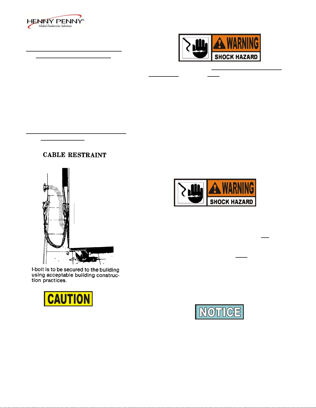
3. See the illustration on the following page for the proper
connection of flexible gas line and cable restraint.
The cable restraint limits the distance the open fryer can be
pulled from the wall. For cleaning and servicing the unit,
the cable must be unsnapped from the open fryer and the
flexible gas line disconnected. This will allow better
access to all sides of the open fryer. The gas line and cable
restraint must
servicing is complete.
703 2-4
be reconnected once the cleaning or
Page 14

Model OFE/OFG-321,322,323,324
2-6. GAS SUPPLY
(Continued)
2-5 2005
Page 15
Model OFE/OFG-321,322,323,324
2-7. GAS LEAK TEST
Prior to turning the gas supply on, be sure the gas valve knob
on the gas control valve is in the OFF position.
Upon initial installation, and after moving the unit, the piping and
fittings should be checked for gas leaks. A simple checking
method is to turn on the gas and brush all connections with a soap
solution. If bubbles occur, it indicates escaping gas.
In this event,
the piping connection must be redone.
To avoid fire or explosion, never use a lighted
match or open flame to test for gas leaks.
Ignited gas could result in severe personal
injury and/or property damage.
2-8. GAS PRESSURE REGULATOR The gas pressure regulator on the gas control valve is
SETTING factory set as follows:
• Natural: 3.5 inches water column (0.87 mbar).
• Propane 10.0 inches water column (2.49 mbar).
The gas pressure regulator has been set by Henny
Penny and is not to be adjusted by the user.
2-9. ELECTRICAL REQUIREMENTS
OFG-320 SERIES
• 230 V, 50 Hz., 1 PH, 6 A
The 120 V gas open fryer requires a 3 wire grounded (earthed)
service and is supplied with a grounded cord and plug. Any 230
volt plug used on the 230 volt unit must conform to all local,
state, and national codes.
To avoid electrical shock, this appliance must be
equipped with an external circuit breaker which
incorporates a 3mm disconnection in all ungrounded
(unearthed) conductors. The main power switch on this
appliance does not
1210 2-6
• 120 V, 50/60 Hz., 1 PH, 12 A
disconnect all line conductors.
Page 16
Model OFE/OFG-321,322,323,324
2-9. ELECTRICAL REQUIREMENTS
OFG-320 SERIES (Continued)
To avoid electrical shock, do not disconnect the ground
(earth) plug.
This fryer must be adequately and
safely grounded (earthed). Refer to local electrical
codes for correct grounding (earthing) procedures or in
absence of local codes, with The National Electrical
Code, ANSI/NFPA No. 70-(the current edition). In
Canada, all electrical connections are to be made in
accordance with CSA C22.1, Canadian Electrical Code
Part 1, and/or local codes.
2-10. ELECTRICAL REQUIREMENTS
OFE-320 SERIES
(Per Well)
Volts Phase Kw Amps
Refer to the table below for supply wiring and fusing.
200-208 3 14.4 40
220/240 3 14.4 40
440-480 3 14.4 17
380-415 3 14.4 20
To avoid electrical shock, this appliance must be
equipped with an external circuit breaker which will
disconnect all ungrounded (unearthed) conductors.
The main power switch on this appliance does not
disconnect all line conductors.
To avoid electrical shock, this fryer must
be
adequately and safely grounded (earthed). Refer to
local electrical codes for correct grounding (earthing)
procedures or in absence of local codes, with The
National Electrical Code, ANSI/NFPA No. 70-(the
current edition). In Canada, all electrical connections are
to be made in accordance with CSA C22.1, Canadian
Electrical Code Part 1, and/or local codes.
DRYWALL CONSTRUCTION
Secure I-bolt to a building stud. Do
not attach to drywall only. Preferred
installation is approximately six
inches to either side of service.
Cable restraint must be at least six
inches shorter than flexible conduit.
CE units require a minimum wire size of 6 mm to be wired
to the terminal block.
Permanently connected electric fryers with casters must be
installed with flexible conduit and a cable restraint, when
installed in the United States. See illustration at left. Holes
are available in the rear fryer frame for securing the cable
restraint to the fryer. The cable restraint does not prevent the
fryer from tipping.
2-7 705
Page 17

Model OFE/OFG-321,322,323,324
2-11. TESTING THE FRYER Each Henny Penny pressure fryer was completely checked
and tested prior to shipment. However, it is good practice to
check the unit for proper operation.
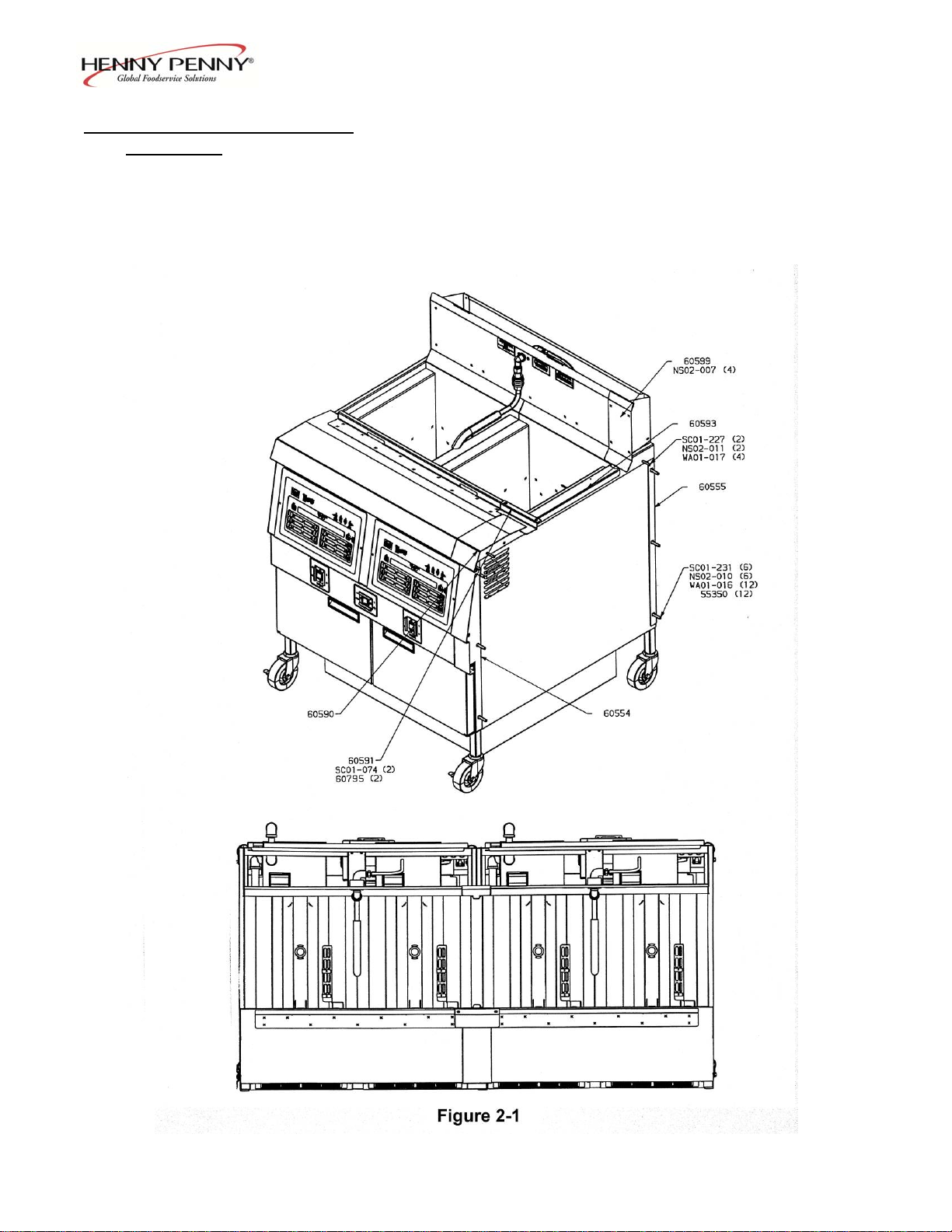
2-12. JOINING INSTRUCTIONS The following instructions are for joining two units together.
The instructions have part numbers in them. Please refer to
figure 2-1 on the following page to visually match the
numbers in the instructions below to the illustration.
1. Remove all hardware from the sides of the two open
fryers.
2. Remove the right control panel assembly from the left
unit and the left control panel assembly from the right
unit.
3. Move the two units side by side with minimal gap.
4. Remove the right front caster from the left unit and the
left rear caster from the right unit. Fasten both casters to
the rear of the unit with wire ties (EF02-041).
5. Position the two open fryers by inserting bolts
(SC01-227) thru the holes in top cover and the pot sides.
Use washer (WA01-017) on both sides of the bolt when
installing. DO NOT TIGHTEN!
6. Position front spacer (60554) between the front of the
two open fryers. Place bolt (SC01-231), backed by
washers (55350 & WA01-016), thru three holes in the
frame capturing the spacer between the frames. Place
washers
(55350 & WA01-016) on bolt before installing nuts
(NS02-010). DO NOT TIGHTEN!
7. Repeat with rear spacer (60555).
8. Tighten all fasteners securely.
9. Place cover (60593) over gap between open fryers.
10. Drill out dimples on rear shroud to 0.250 diameter holes.
11. Apply silicon around edge of unfinished side of rear
cover (60599). Install rear cover (60599) with #8 nuts
(NS02-007).
211 2-8
Page 18
Model OFE/OFG-321,322,323,324
2-12. JOINING INSTRUCTIONS 12. Apply silicon around edge of unfinished side of top cover
(Continued) (60590) and basket rest cover (60591). Position top cover
(60590) on open fryer top cover and install basket rest
cover (60591) using #10 screws and nuts (SC01-074 &
60795).
13. Apply silicon to any gaps that may be left.
2-9 1005
Page 19
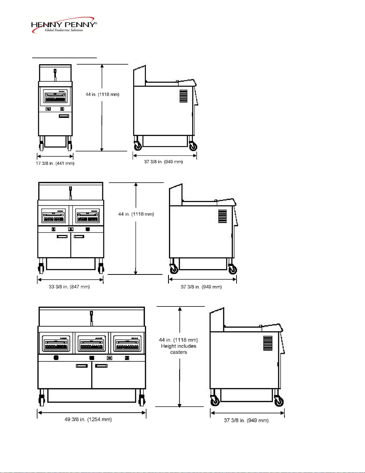
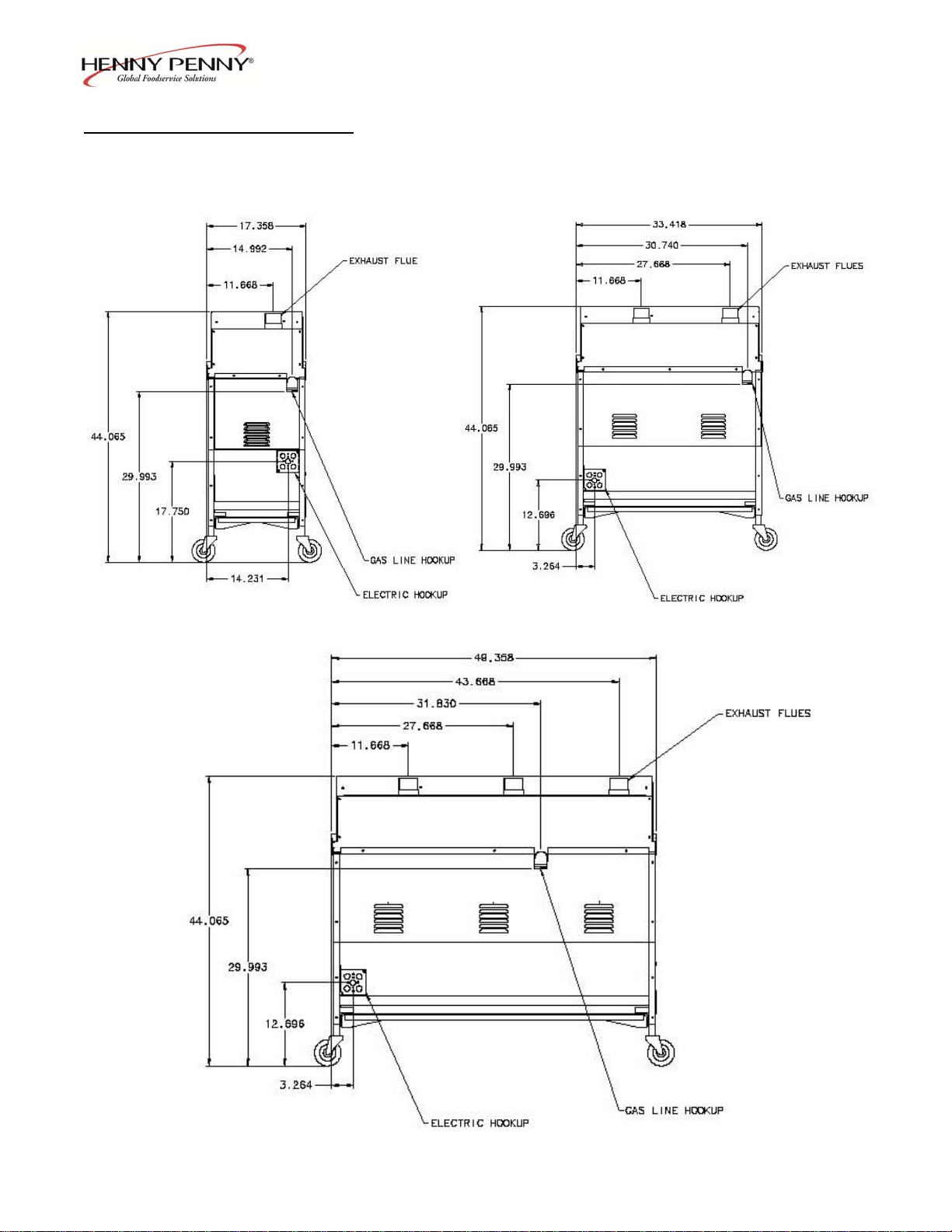
2-13. DIMENSIONS
Model OFE/OFG-321,322,323,324
OFX-321
OFX-322
OFX-323
211 2-10
Page 20
Model OFE/OFG-321,322,323,324
(
)
2-13. DIMENSIONS (Continued)
2-11 211
OFG-321 OFG-322
OFG-32X Flue & Gas Line Dimensions
All views are from rear of fryers
OFG-323
Page 21

Model OFE/OFG-321,322,323,324
SECTION 3. OPERATION
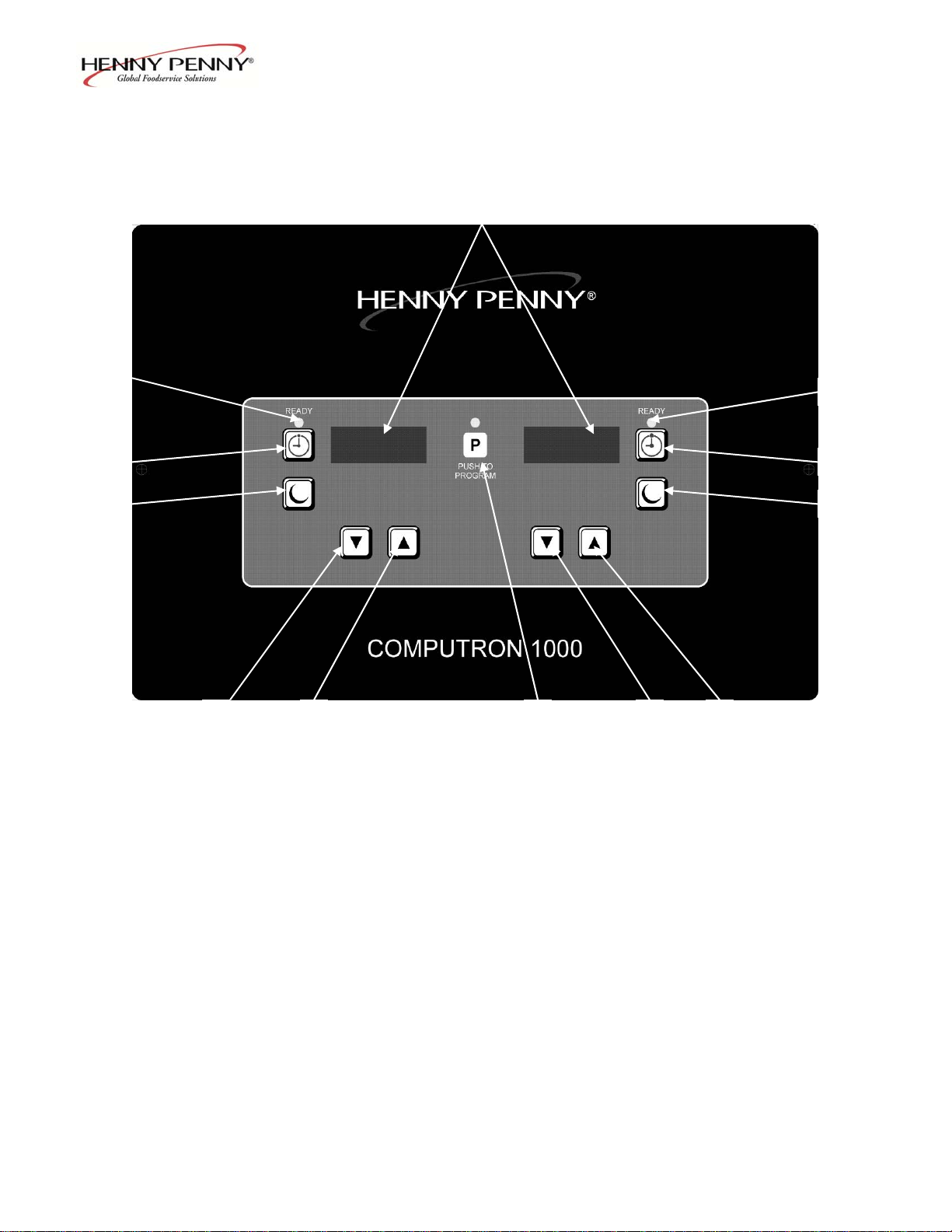
3-1. OPERATING COMPONENTS Reference Figure 3-1.
C1000 CONTROLS
Fig. Item Description Function
No. No.
3-1 1 Digital Display Shows the shortening temperature, the timer countdown in
the Cook Cycle, and the selections in the Program Mode; the
temperature of the shortening can be shown by pressing
once, or twice to view set-point temperature;
if shortening temperature exceeds 425F (218C), the display
reads “E-5, FRYER TOO HOT”
3-1 2 This LED lights when the shortening temperature is within 5
of the setpoint temperature, signaling the operator that the
shortening temperature is now at the proper temperature for
dropping product into the frypot
3-1 3 The timer buttons are used to start and stop Cook Cycles
3-1 4 The idle buttons are used to start an Idle Mode which reduces
the temperature of the shortening during non-use periods;
press and hold to exit the Idle Mode
3-1 5 The program button is used to access the Program Modes;
also, once in the Program Mode, it is used to advance to the
next parameter
3-1 6 & 7 Used to adjust the value of the currently displayed setting
in the Program Mode and to change set-point temperature for
the left frypot, or basket
3-1 8 & 9 Used to adjust the value of the currently displayed setting
in the Program Mode and to change set-point temperature for
the right frypot, or basket
Proceed onto Section 3-4, Filling or Adding Shortening
108 3-1
Page 22
Model OFE/OFG-321,322,323,324
6
7 5 8 9
Figure 3-1
3-2 108
Page 23

Model OFE/OFG-321,322,323,324
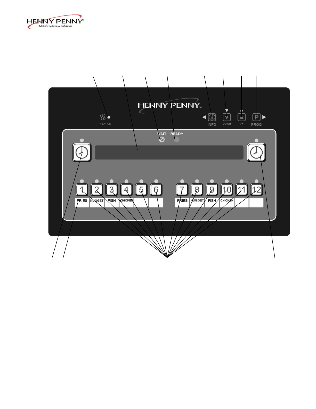
3-2. OPERATING COMPONENTS Figure 3-2 shows the function of the 12 button timer control,
6 & 12 BUTTON CONTROLS and Figure 3-3 shows the function of the 6 button timer control.
Fig. Item Description Function
No. No.
3-1 1 This LED lights when the control calls for heat,
3-2 and the burners come on and heat the shortening
3-1 2 Digital Displays Shows the shortening temperature, the timer countdown in
3-2 the Cook Cycle, and the selections in the Program Mode; the
temperature of the shortening can be shown by depressing
the INFO button; if the temperature exceeds 425F (218C),
the display reads “E-5, FRYER TOO HOT”
3-1 3 WAIT LED Once the open fryer is out of the Melt Cycle, this LED lights,
3-2 signaling the operator that the shortening temperature is not
proper temperature for dropping product into the frypot
3-1 4 READY LED This LED lights when the shortening temperature
3-2 is within 5 of the setpoint temperature, signaling the
operator that the shortening temperature is now at the proper
temperature for dropping product into the frypot
3-1 5 Press to display the following fryer information and status:
3-2 a. The temperature of the shortening
b. The temperature setpoint
c. Filter status
d. The number of times filtered today
e. The average no. of filters per day
f. No. of times Cook Cycle was stopped early today
g. No. of times Cook Cycle was stopped early in past week
e. Date and time
3-1 6 & 7 Used to adjust the value of the currently displayed setting
3-2 in the Program Mode
3-1 8 Used to access the Program Modes; also, once in the
3-2 Program Mode, it is used to advance to the next parameter
3-1 9 START/STOP Used to start and stop Cook Cycles; also de-activates
3-2 Button the quality timer at the end of a Hold Mode
3-1 10 Menu Card Displays the food product associated with each product
3-2 Window selection button below; the menu card strip is located
behind the decal
3-1 11 Product Select Used to select which food products are to be cooked
3-2 Buttons (on auto-lift open fryers, the 6 and 12 product buttons are basket
lift buttons)
1005 3-3
at the
Page 24
Model OFE/OFG-321,322,323,324
1 2 3 4 5 6 7 8
9 10 11 9
Figure 3-2
3-4 103
Page 25

Model OFE/OFG-321,322,323,324
1 2 3 4 5 6 7 8
9 10 11 9
Figure 3-3
103 3-5
Page 26

Model OFE/OFG-321,322,323,324
3-3. CLOCK SET
Upon initial start-up or PC board replacement, if
“CLOCK SET” automatically appears in the display,
skip steps 1, 2 and 3.
1. Press and hold for 5 seconds until “LEVEL 2”
shows in display.
2. Release , then press twice. “CLOCK SET”
then “ENTER CODE” shows in display.
3. Press .
4. Display shows “CS-1” then “SET” then “MONTH”,
with the month flashing.
5. Press to change the month.
6. Press . Display shows “CS-2” then “SET” then
“DATE”, with the date flashing.
7. Press to change the date.
8. Press . Display shows “CS-3” then “SET” then
“YEAR”, with the year flashing.
9. Press to change the year.
10. Press . Display shows “CS-4” then “SET” then
“HOUR”, with the hour and “AM” or “PM”
flashing.
11. Press to change the hour and AM/PM
setting.
12. Press . Display shows “CS-5” then “SET” then
“MINUTE”, with the minutes flashing.
306
3-6
Page 27

Model OFE/OFG-321,322,323,324
3-3. CLOCK SET 13. Press to change the minutes.
(Continued)
14. Press . Display shows “CS-6” then “CLOCK
MODE”, along with “1.AM/PM”.
15. “1.AM/PM” is 12 hour time, “2.24-HR” is 24 hour
time. Press to change.
16. Press . Display shows “CS-7” then “DAYLIGHT
SAVINGS ADJ”, along with “2.US”.
17. Press to change to the following:
a. “1.OFF” = No automatic adjustments for Daylight
Savings Time.
b. “2.US” = Automatically applies United States Daylight
Saving Time adjustment. For 2006 & earlier: DST starts
on first Sunday in April, and ends on last Sunday in
October. For 2007 & later: DST starts on second Sunday
in March, ends on first Sunday in November.
c. “3.EURO” = Automatically applies European (CE)
Daylight Savings Time adjustment. DST activated on the
last Sunday in March. DST de-activated on the last
Sunday in October.
d. “FSA” = Old “First Sunday in April” schedule, in case
US ever goes back to old schedule. DST starts on the
first Sunday in April. DST ends on the last Sunday in
October.
18. Clock Set is now complete. Press and hold to
exit.
306 3-7
Page 28

Model OFE/OFG-321,322,323,324
3-4. FILLING OR
ADDING SHORTENING The shortening level must always be above the heating
elements when the fryer is heating and at the frypot
level indicators on the rear of the frypot. Failure to
follow these instructions could result in a fire and/or
damage to the fryer.
When using solid shortening, it is recommended to melt
the shortening on an outside heating source before
placing it in the frypots. The heating elements or
burner tubes must be completely submerged in
shortening. Fire or damage to the frypot could result.
1. It is recommended that a high quality frying shortening
be used in the open fryer. Some low grade shortenings
have a high moisture content and will cause foaming
and boiling over.
Wear gloves to avoid severe burns when pouring hot
shortening into frypot. Shortening and all metal
parts that are in contact with the shortening are
extremely hot, and take care to avoid splashing.
2. The full frypots require 65 lbs. (29.5 kg) of shortening,
while the split frypot requires 25 lbs. (11.3 kg.). All
gas frypots, and some electric frypots, have 2 level
indicator lines inscribed on the rear wall of the
frypot which shows when the heated shortening is at the
proper level. Some electric models only have 1 level
indicator line on the frypots.
3. Cold shortening should be filled to the lower indicator
when the frypot has 2 indicator lines, and a ½ inch
(12.7 mm) below a single indicator line.
3-8 208
Page 29

Model OFE/OFG-321,322,323,324
The Computron 1000 controls are available on both split
3-5. C1000 OPERATIONS
electronic controls frypot and full frypot fryers. The following is a brief description
AND PROCEDURES
of the operating procedures for fryers with these controls.
1. Be sure the drain valve is in the closed position.
2. Place basket support inside of frypot.
3. Make sure frypot is filled with shortening to the proper
level.
4. Display shows “OFF” until power switch is turned to the
ON position. Display now shows the cook time and the unit
automatically goes into the Melt Cycle until the
shortening temperature reaches 250F (121C). The
control then automatically exits the Melt Cycle.
The OFG-320 series open fryer has several safety devices
which shuts-down the gas supply when they are activated.
The above procedures should be followed to restart the open
fryer and if the shut down is repeated, a qualified technician
should be notified.
The Melt Cycle may be bypassed, if desired, by pressing
and holding for 3 seconds.
Do not bypass the Melt Cycle unless enough shortening
on gas fryers and elements on electric fryers. If Melt
Cycle is bypassed before all burner tubes or elements
are covered, excessive smoking of the shortening, or a
fire will result.
5. Once out of the Melt Cycle, the shortening is heated
until lights and the cook time is displayed.
Thoroughly stir shortening to stabilize the temperature
throughout the frypots.
6. Before loading product into the baskets, lower baskets
into the hot shortening to keep the product from
sticking to the baskets.
7. Once the shortening temperature has stabilized at the
setpoint temperature, lower the basket with product into
the frypot.
208 3-9
Page 30

Model OFE/OFG-321,322,323,324
3-5. C1000 OPERATIONS
AND PROCEDURES
(Continued)
Do not overload, or place product with extreme
moisture content into the basket. 12.5 lbs. (5.7 kg)
is the maximum amount of product per frypot
(6.25 lbs. (2.8 kg) maximum for the split frypot
fryers). Failure to follow these directions can result
in shortening overflowing the frypot. Serious burns
or damage to the unit could result.
9. If the right basket was dropped into the shortening, then
press the right .
If the left basket was dropped, then press the left .
10. The timer on the appropriate side (right or left) starts
counting down.
The timing operation of the two sides of the control
is entirely independent of each other. One may be set,
started, or stopped without affecting the other.
11. At the end of the Cook Cycle a tone will sound and the
display flashes “DONE”. Press button and lift the
basket from the shortening.
Timer Programming
3-6. C1000 PROGRAMMNG
1. Anytime the cook time is displayed, press
INSTRUCTIONS
under the appropriate display to change the cook time.
Set-Point Temperature Programming
1. Press once to view the actual shortening
temperature and press again to view the set-point
temperatue.
2. While the set-point temperature is in the display, press
to change the set-point temperature.
If “LOCK” shows in display when pressing ,
the controls are locked and must be unlocked before
changing the time or set-point temperature. See C1000
Special Programming Section.
3-10 208
Page 31

Model OFE/OFG-321,322,323,324
Special Programming is used to set the items below:
3-7. C1000 SPECIAL
PROGRAMMING
1. To enter Special Programming, turn off power switch
(either side). Press and hold and turn the power
switch back on.
2. “SPEC” “PROG” followed by, “DEG” “°F” or “°C”. Use
to choose “°F” or “°C”.
3. Press and “INIT” shows in the display.
Press and hold the right and display shows “In-3”,
4. Press and “LOCK” or “UNLOCK” shows in the
“UNLOCK”.
5. Press and “FRYR” shows in left display and the right
6. Press and “FRYR” shows in the display. Use
to change the fryer type: “ELEC” for electric
7. Press and “VAT” shows in the display. Use
to choose “SPLIT” or FULL” vat (frypot) type.
8. Press and “MELT” and “Solid” or “LIQD” shows in
9. Press and hold to exit Special Programming at any
1209 3-11
Fahrenheit or Celsius
Initialize System
Lock or Unlock Controls
Fryer Type – Open or Pressure
Heat Source – Electric; Gas w/standing pilot;
Gas w/electronic ignition; Gas-Induced Draft
Vat Type - Split or Full Vat (frypot)
Oil Type - Solid or Liquid
“In-2”, “In-1” followed by “Init Sys” “DONE DONE”. The
controls now are reset to factory parameters, the time set to
0:00 and temperature 190°F or 88°C.
displays. Use to choose “LOCK” or
display should show “OPEN”. Use to change
from “PRES” to “OPEN” if needed.
models; “GAS” for units with standing pilot; SSI for units
with solid state ignition; IDG for units with induced draft gas
burners.
the displays. Use to choose “Solid”, if using
solid shortening, or “LIQD”, if using liquid shortening.
time.
Page 32

Model OFE/OFG-321,322,323,324
The Henny Penny Open Fryer has electronic controls
3-8. BASIC OPERATIONS
for each frypot. The following is brief description of the
AND PROCEDURES
operating procedures for controls with 6 product buttons.
(6 Product Controls)
1. Be sure the drain valve is in the closed position.
2. Place basket support inside of frypot.
4. Move power switch to the ON position. Unit automatically
goes into the Melt Cycle until the shortening temperature
reaches 230F (110C). The control then automatically exits
the Melt Cycle.
The Melt Cycle may be bypassed, if desired, by pressing a
product button and holding it for five seconds.
3. Make sure frypot is filled with shortening to the proper level
The OFG-320 series open fryer has several safety devices
which shuts-down the gas supply when they are activated.
The above procedures should be followed to restart the open
fryer and if the shut down is repeated, a qualified technician
should be notified.
Do not bypass the Melt Cycle unless enough shortening
has melted to completely cover all of the burner tubes
on gas fryers and elements on electric fryers. If Melt
Cycle is bypassed before all burner tubes or elements
are covered, excessive smoking of the shortening, or a
fire will result.
5. Once out of the Melt Cycle, the WAIT LED flashes
until the setpoint temperature has been reached. Then
the READY LED lights, and the selected product
displays on the left and right side of the display.
The timing operation of the two sides of the control
is entirely independent. They may be set, started, or
stopped without affecting each other.
If the Energy Save Mode is activated for gas fryers, the pilot
light goes out and the blower turns off, if the fryer is idle for
2 minutes with the READY LED lit. Starting a Cook Cycle
exits the Energy Save Mode, or if the shortening temperature
drops to where the READY LED goes out, the fryer resumes
normal heat-up mode until the READY LED comes back on.
(See SP-19).
3-12 306
Page 33

Model OFE/OFG-321,322,323,324
6. Thoroughly stir shortening to stabilize the temperature
3-8. BASIC OPERATIONS
throughout the frypots.
AND PROCEDURES
(6 Product Controls)
7. Before loading product into the baskets, lower baskets
(Continued)
into the hot shortening to keep the product from
sticking to the baskets.
8. Once the shortening temperature has stabilized at the
setpoint temperature, the operator can then lower the
basket with product into the frypot.
Do not overload, or place product with extreme
moisture content into the basket. 12.5 lbs. (5.7 kg)
is the maximum amount of product per frypot
(15.0 lbs. (6.8 kg) maximum for auto-lift open
fryers). Failure to follow these directions can result
in shortening overflowing the frypot. Serious burns
or damage to the unit could result.
9. If the right basket was dropped into the shortening, then
the right START/STOP button should be pressed. If the
left basket was dropped, then the left START/STOP button
should be pressed.
10. Once the START/STOP button has been pressed, the timer
on the appropriate side (right or left) will start counting
down.
11. At the end of the Cook Cycle a tone will sound and the
display will flash “DONE”. Press the START/STOP
button and lift the basket from the shortening.
12. The display will show which product it is ready to time
down. If a hold time was programmed, the controller
automatically starts the hold timer. The display
alternately shows the product selected and the quality
time remaining in minutes. If a different product is
selected during the Hold Cycle, the display only shows
the product selected. To view the hold time remaining,
push the INFO button.
13. At the end of the Hold Mode, a tone will sound and the
display will flash QUALITY and the product it was timing.
Press and release the START/STOP button. The display
shows the product it is ready to start timing for frying
703 3-13
.
Page 34

Model OFE/OFG-321,322,323,324
3-9. BASIC OPERATIONS Henny Penny Open Fryer models OFE/OFG are available
AND PROCEDURES
(12 Product Controls/Auto-lift)
with 12 product button controls. Also, models OEA/OGA
are available with 12 button controls, equipped with auto-lift
features. The auto-lift controls, allow the baskets to be
automatically lowered into the shortening, at the beginning of
the cook cycle, and raised from the shortening at the end of
the cycle.
1. Be sure the drain valve is in the closed position.
2. Fill the frypot with shortening.
3. Move POWER switch to the ON position. Unit
automatically goes into the Melt Cycle. When the
temperature reaches 250F (121C), the control exits
the Melt Cycle and heats the shortening until the
temperature setting is reached.
The OFG-320 series open fryer has several safety devices
which shuts down the gas supply when they are activated.
The above procedures should be followed to restart the
fryer and if the shut down is repeated, a qualified
technician should be notified.
The Melt Cycle may be bypassed if desired, by pressing
a product button and holding it for five seconds.
Do not bypass the Melt Cycle unless enough shortening
on gas fryers and elements on electric fryers. If Melt
Cycle is bypassed before all burner tubes or elements
are covered, excessive smoking of the shortening, or a
fire will result.
4. Once out of the Melt Cycle, the WAIT LED flashes
until the setpoint temperature has been reached. Then
the READY LED illuminates.
If the Energy Save Mode is activated for gas fryers, the
pilot light goes out and the blower turns off, if the fryer
is idle for 2 minutes with the READY LED lit. Starting
shortening temperature drops to where the READY
LED goes out, the fryer resumes normal heat-up mode
until the READY LED comes back on. (See SP-19).
3-14 306
Page 35

Model OFE/OFG-321,322,323,324
3-9. BASIC OPERATIONS
AND PROCEDURES
(12 Product Controls/Auto-Lift)
(Continued)
The timing operation of the two sides of the control
can be programmed entirely independent from each
other for 2 half baskets, or as one timer for a single full
sized basket which will set on both lifts. The default
setting from the factory is for two half sized baskets.
To change to a single full size basket setting, push and
hold the #1 product button while turning on the
POWER switch. To change back to the two basket
mode, push and hold the #2 product button while
turning on the POWER switch.
5. Thoroughly stir shortening to stabilize the temperature
throughout the frypots.
6. Before loading product into the baskets, lower baskets
into the hot shortening to keep the product from
sticking to the baskets.
7. Once the shortening temperature has stabilized at the
setpoint temperature, the operator may now place the
baskets into the shortening (or for auto-lift open fryers,
lift basket onto the hangers). Place product into the
basket.
Do not overload, or place product with extreme
moisture content into the basket. 12.5 lbs. (5.7 kg)
is the maximum amount of product per frypot (15.0
lbs. (6.8 kg) maximum for auto-lift open fryers).
Failure to follow these directions can result in
shortening overflowing the frypot. Serious burns or
damage to the frypot could result.
8. If the right basket is to be lowered into the shortening,
then one of the right product buttons should be pressed.
If the left basket is to be lowered, then one of the left
product buttons should be pressed.
9. The timer on the appropriate side will start counting
down. (On auto-lift open fryers, the basket will
automatically lower into the shortening.)
703 3-15
Page 36

Model OFE/OFG-321,322,323,324
3-9. BASIC OPERATIONS
AND PROCEDURES
(12 Product Controls/Auto-Lift)
automatically rises out of the shortening.) To stop the
(Continued)
A different product can be selected during the first
11. The display will show which product it is ready to time
down. If a hold time was programmed, the controller
will automatically start the hold timer. The display will
alternately show the product selected and the hold
time remaining in minutes. If a different product is
selected during the Hold Cycle, the display will only
show the product selected.
12. At the end of the Hold Cycle, a tone sounds and the
display flashes “QUALITY”, and the product it was
timing. Press and release the TIMER button.
10. At the end of the Cook Cycle, a tone sounds and the
display shows “DONE”. Lift the basket from the
shortening. (On auto-lift open fryers, the basket
“DONE” beeper, either press the timer button, or
the product button.
minute of cooking.
In the Cook Mode, when “FILTER SUGGESTED”
shows in the display, the operator has the option to
filter at this time, or to continue cooking. But, if the
operator continues cooking, a filter lockout occurs
within the next Cook Cycle, or two.
When “FILTER LOCKOUT”, then “YOU *MUST* FILTER
NOW........” shows in the display, the PROG button is the
only button that will function, until the unit is filtered.
3-10. CARE OF SHORTENING
FOLLOW THE INSTRUCTIONS BELOW TO
AVOID SHORTENING OVERFLOWING THE
FRYPOT, WHICH COULD RESULT IN SERIOUS
BURNS, PERSONAL INJURY, FIRE, AND/OR
PROPERTY DAMAGE.
1. Maintain the shortening at the proper cooking level.
Add fresh shortening as needed.
3-16 703
Page 37

Model OFE/OFG-321,322,323,324
3-10. CARE OF SHORTENING 2. To protect and get the maximum life out of the
(Continued)
lower when the fryer is not in immediate use.
Deteriorated shortening smokes badly, even at lower
temperatures.
shortening, lower the temperature to 275° F (135° C) or
3. Taste the cold shortening daily for signs of bad flavor.
Discard any shortening which has a bad flavor or shows
signs of excessive foaming or boiling. Keep the frypot
clean.
WITH PROLONGED USE, THE FLASHPOINT OF
SHORTENING IS REDUCED. DISCARD SHORTENING IF IT SHOWS SIGNS OF EXCESSIVE
SMOKING OR FOAMING. SERIOUS BURNS,
PERSONAL INJURY, FIRE, AND/OR PROPERTY
DAMAGE COULD RESULT.
3-11. FILTERING OF
SHORTENING
1. Turn the main switch to the OFF position. Remove and
clean the fry basket in soap and water. Rinse thoroughly.
Best results are obtained when shortening is filtered at the
normal frying temperature.
2. Use a metal spatula to remove any build up from the sides
of the frypot. Do not scrape burner tubes on the gas
models, or heating elements on electric models.
Scraping the electric fryer elements, or burner tubes
of the gas frypot, produces scratches in these surfaces
causing breading to stick and burn.
The filter drain pan must be as far back under fryer as
it will go and the cover in place. Be sure the hole in the
cover lines up with the drain before opening the drain.
Failure to follow these instructions causes splashing of
shortening and could result in personal injury.
Surfaces of fryer and baskets will be hot. Use care
when filtering to avoid getting burned.
703 3-17
Page 38

Model OFE/OFG-321,322,323,324
3-11. FILTERING 3. Open door(s) under unit, and slowly turn drain
OF SHORTENING valve handle a half turn. Leave for a few minutes, then
(Continued) slowly, fully open drain valve. This prevents much
splashing of the hot shortening as it drains.
4. As the shortening drains from the frypot, use brushes
to clean the sides of the frypot and the burner tubes or
heating elements. If the drain fills with breading, use
straight white brush to push excess breading into the filter
drain pan.
5. When all of the shortening has drained, scrape or brush the
sides and the bottom of the frypot.
6. Rinse the frypot as follows:
Standard 322, 323, & 324 Open fryers
a. Close the drain valve.
DRAIN VALVE HANDLE FILTER VALVE HANDLE b. Position return line over empty frypot.
c. Move the pump switch to the pump position.
d. Fill the frypot 1/3 full, then turn off pump.
e. Wash down and scrub the sides of the frypot with
the brushes.
f. After the sides and bottom are cleaned, open the
drain valve.
321 Open fryers-After April, 2002
a. Close the drain valve. Figure 3-3.
b. Open the filter valve. Figure 3-3.
c. Move the pump switch to the pump position.
d. Fill the frypot 1/3 full, then turn off pump.
e. Wash down and scrub the sides of the frypot with
the brushes.
FILTER UNION FEMALE QUICK- f. After the sides and bottom are cleaned, open the
DISCONNECT drain valve.
Figure 3-3
IF THERE ARE AIR BUBBLES COMING UP
IN THE SHORTENING BEFORE ALL
SHORTENING IS PUMPED UP, IT’S POSSIBLE
THAT THE FILTER CONNECTION AT THE
UNION ON THE FILTER TUBE IS NOT
TIGHTENED PROPERLY. IF SO, TURN
OFF THE PUMP AND WEAR PROTECTIVE
GLOVES OR CLOTH WHEN TIGHTENING
THE UNION. THIS UNION WILL BE HOT.
SEVERE BURNS COULD RESULT.
3-18 703
Page 39

Model OFE/OFG-321,322,323,324
3-11. FILTERING With Optional Filter Rinse Hose
OF SHORTENING a. Open the door and pull the collar back on the female
(Continued) quick-disconnect. Attach the male quick disconnect
on the filter rinse hose, onto the female fitting.
Figure 3-3.
b. Point the hose nozzle down into the frypot, close the
filter valve, and move the PUMP switch to the PUMP
position. Hold nozzle carefully to avoid excessive
splashing. Figure 3-4.
Use caution to prevent burns from splashing
hot shortening.
c. Rinse the frypot interior, especially hard to clean areas
like the frypot bottom and heating elements.
d. After sufficient rinsing, close the drain valve.
Figure 3-4 e. Turn the PUMP switch to the OFF position.
ONLY CONNECT AND DISCONNECT THE
FILTER RINSE HOSE WHEN THE PUMP
SWITCH IS IN THE OFF POSITION. FAILURE
TO DO THIS WILL RESULT IN SEVERE
BURNS FROM HOT SHORTENING SPRAYING
FROM THE FITTINGS. USE A DRY CLOTH OR
PROTECTIVE GLOVE TO AVOID BURNS.
to drain back into the frypot.
f. Detach hose, and raise the fitting end of the hose high
FILTER HANDLE for a minute to allow remaining shortening in the hose
Autolift Open fryers
a. Close the drain valve.
b. Turn filter handle to the on position. Figure 3-5.
c. Fill the frypot 1/3 full.
d. Turn filter handle to the OFF position.
Figure 3-5
Use care when reaching across a frypot of hot
shortening. Severe burns could result.
703 3-19
Page 40

Model OFE/OFG-321,322,323,324
e. Wash down and scrub the sides of the frypot with
3-11. FILTERING
the brushes.
OF SHORTENING
f. After the sides and bottom are cleaned, open the drain
(Continued)
valve.
is slow from faucet, use cloth or protective gloves to
tighten the filter union. This union will be hot.
Severe burns could result.
On 322, 323 and 324 open fryers, if shortening flow
7. Pump all of the shortening out of the filter drain pan and
back into the frypot.
8. When the pump is pumping air only, move the pump switch
from PUMP to OFF, or on auto-lift open fryers, turn filter
handle to OFF.
321 Open fryers – When the pump is pumping air only, the
shortening in the frypot appears to be boiling. Close the
filter valve first, and then move the pump switch to the OFF
position. This keeps the filter pump and lines from filling
up with shortening.
9. Check the level of the shortening in the frypot. Add fresh
shortening if necessary, until it reaches the top level
indicator line on the rear wall of the frypot.
About 10 to 12 filterings can be made with one filter
paper envelope, depending on:
the quantity and type of product fried and
filtered
the type of breading used
the amount of crumbs left inside the filter drain
pan. When the filter screen assembly and filter
paper become clogged, and the pumping flow
slows, clean the filter screen assembly and
change the filter envelope.
10. To continue cooking, move the main POWER switch to
the ON position, and shortening reheats.
3-20 703
Page 41

Model OFE/OFG-321,322,323,324
3-12. FILTER PUMP PROBLEM To help prevent filter pump problems:
PREVENTION
1. Properly install paper envelope over the filter screens.
Fold the open end of the envelope, and clamp with retaining
clips so that crumbs cannot enter. Figure 3-6.
2. Pump shortening, until no shortening is coming from the
nozzle.
Figure 3-6
3-13. FILTER PUMP MOTOR In the event it overheats, the filter pump motor is equipped with a
PROTECTOR – MANUAL RESET
waiting 5 minutes to allow the motor to cool, press the reset
button. It takes some effort to reset the motor. A screwdriver can
be used to help press reset button. Figure 3-7.
Servicing of the filter pump is done at the rear of the unit. If
service is required, disconnect the open fryer from the electrical
and/or gas power source, and pull the open fryer out from the
wall to gain access to rear.
manual reset button located on the rear of the motor. After
Figure 3-7
To prevent burns caused by splashing shortening, turn
the unit's filter PUMP switch to the OFF position
before resetting the filter pump motor’s manual reset
protection device.
3-14. CHANGING THE FILTER The filter envelope should be changed after 10-12 filterings or
ENVELOPE
whenever it becomes clogged with crumbs. Proceed as follows:
cloth, or severe burns could result.
Use care to prevent burns caused by splashing of hot
shortening.
1. Move the main POWER switch to the OFF position.
2. Disconnect the filter union and remove the filter drain
pan from beneath the frypot.
703 3-21
The filter union could be hot. Wear protective glove or
Page 42

Model OFE/OFG-321,322,323,324
3-14. CHANGING THE FILTER 3. Remove cover from filter drain pan and lift the filter
ENVELOPE
(Continued)
5. Unthread the standpipe from the filter screen assembly.
screen assembly from the drain pan.
4. Wipe the shortening and crumbs from the filter drain pan.
Clean the drain pan with soap and water. Thoroughly rinse
with hot water.
6. Remove the crumb catcher and clean with soap and water.
Rinse thoroughly with hot water.
7. Remove the filter clips and discard the filter envelope.
8. Clean the top and bottom filter screen with soap and water.
Rinse thoroughly with hot water.
and the standpipe are thoroughly dry before assembly of the
filter envelope or water will dissolve the filter paper.
9. Assemble the top filter screen to the bottom filter screen.
10. Slide the screen into a clean filter envelope.
11. Fold the corners in and then double fold the open end.
clips.
15. Connect the filter union by hand. Do not use a wrench to
tighten.
16. The open fryer is now ready to operate.
3-22 703
Be sure that the filter screens, crumb catcher, filter clips
12. Clamp the envelope in place with the two filter retaining
13. Replace the crumb catcher screen on top of the filter paper.
Screw on the standpipe assembly.
14. Place complete filter screen assembly back into filter drain
pan, replace cover, and slide pan back into place beneath the
open fryer.
Page 43

Model OFE/OFG-321,322,323,324
3-15. CLEANING After the initial installation of the open fryer, as well as before
THE FRYPOT
cleaned as follows:
every change of shortening, the frypot should be thoroughly
1. Turn the main POWER switch off.
The filter drain pan must be as far back under fryer as it
will go, and the cover in place. Be sure the hole in the
cover lines up with the drain before opening the drain.
Failure to follow these instructions causes splashing of
shortening and could result in personal injury.
Moving the fryer or filter drain pan while containing hot
shortening is not recommended. Hot shortening can
splash out and severe burns could result.
Always wear chemical splash goggles or face shield and
protective rubber gloves when cleaning the frypot as the
cleaning solution is high in alkaline. Avoid splashing or
other contact of the solution with your eyes or skins.
Severe burns may result. Carefully read the instructions
on the cleaner. If the solution comes in contact with
your eyes rinse thoroughly with cool water and see a
physician immediately.
2. If hot shortening is present in the frypot, it must be drained
by slowly opening the drain valve handle one half turn.
Leave for a few minutes, then slowly open the valve to full
open position.
3. Close the drain valve. Discard the shortening using the
shortening shuttle.
4. Remove the filter screen assembly from the filter drain pan.
cloth, or severe burns could result.
The filter union could be hot. Wear protective glove or
5. Fill the frypot to the level indicator with hot water. Add
4 ozs. (0.12 liters) of open fryer cleaner to the water and mix
thoroughly. The fry basket can be placed inside the frypot
for cleaning.
703 3-23
Page 44

Model OFE/OFG-321,322,323,324
6. Use the Clean-Out Mode (see section 3-13), or turn the main
3-15. CLEANING
POWER switch to the ON position and POWER switch to the ON position and set temperature to
THE FRYPOT
195 F (90.5 C).
(Continued)
7. When the solution reaches 195 F (90.5 C), turn the main
POWER switch to the OFF position.
8. Let the cleaning solutions stand for 15 to 20 minutes with
the power off.
9. Using the open fryer brush (never use steel wool), scrub the
inside of the frypot.
boil over, immediately turn the power switch to OFF
If the cleaning solution in the frypot starts to foam and
or damage to components could result.
Do not use steel wool, other abrasive cleaners or cleaners/
sanitizers containing chlorine, bromine, iodine or ammonia
chemicals, as these will deteriorate the stainless steel
material and shorten the life of the unit.
Do not use a water jet (pressure sprayer) to clean the
unit, or component damage could result.
10. After cleaning, open the drain valve and drain cleaning
solution from the frypot into the filter drain pan and discard.
11. Replace the empty filter drain pan, close the drain valve, and
refill the frypot with plain hot water to the proper level.
12. Add approximately 8 ozs. (0.24 liters) of distilled vinegar.
Use the Clean-Out Mode (see section 3-13), or bring the
solution back up to 195 F (90.5 C).
13. Using a clean brush, scrub the interior of the frypot. This
will neutralize the alkaline left by the cleaning compound.
14. Drain the vinegar rinse water and discard.
15. Rinse down the frypot using clean, hot water.
Make sure the inside of the frypot, the drain valve opening,
and all the parts that will come in contact with new
shortening are as dry as possible.
3-24 207
16. Thoroughly dry the filter drain pan and the frypot interior.
Page 45

Model OFE/OFG-321,322,323,324
17. Replace the clean filter screen assembly in the drain
3-15. CLEANING
pan, replace cover, and install filter drain pan under
THE FRYPOT
open fryer.
(Continued)
18. Refill the frypot with fresh shortening.
Henny Penny has the following cleaners available:
Foaming Degreaser - Part no. 12226
PHT Liquid Cleaner - Part no. 12135
PHT Dry Powder Cleaner - Part no. 12101
See your local distributor for details.
3-16. CLEAN-OUT MODE When heating the cleaning solution and vinegar solutions,
(6 & 12 Product Controls Only) turn the POWER switch to the ON position. When the fryer
starts the Melt Cycle, press and hold then
“CLEAN-OUT ?”, “1=YES 2=NO” shows in display.
Press to start Clean-Out Mode. The fryer displays
“*CLEAN-OUT MODE*” and heats up to a
preprogrammed temperature, up to 195˚F (91˚C), then
automatically begins a preset timed countdown. Use
the buttons, if necessary, to adjust the temperature
and keep the cleaning solution from boiling over.
Once the timed countdown is complete and display shows
“CLEANING DONE”, refer back to the Cleaning the Frypot
procedures for more detailed instructions.
See Special Program Modes SP-20 and SP-21 to preset
the temperature and time.
208 3-25
Page 46

Model OFE/OFG-321,322,323,324
1. Connect the female quick disconnect, that is attached to the
3-17. OPERATING INSTRUCTIONS
hose in the rear of the open fryer, to the correct male quick
disconnect at the wall. Once attached, the hose can remain
connected unless the open fryer is moved.
FOR OPTIONAL DIRECTCONNECT SHORTENING
SYSTEM
Figures 3-8 & 3-9.
The hose is to be attached to shortening return
line only for the system to work properly.
Figure 3-8 2. Open the drain valve and drop the shortening from the
desired frypot, into the filter drain pan.
3. Pull diverter-handle towards you, in the back of the fryer,
from FILTER to DISCARD. Figure 3-10.
This handle could be hot! Use protective gloves or
Figure 3-9 cloth when turning diverter-handle, or burns could
result.
4. Once all shortening is gone from frypot, turn the filter
pump switch to the ON position. Shortening is now
pumped from the filter drain pan.
3-26 703
Figure 3-10
Page 47

Model OFE/OFG-321,322,323,324
3-17. OPERATING INSTRUCTIONS
5. Once all the shortening is out of the filter drain pan, turn the
FOR OPTIONAL DIRECTCONNECT SHORTENING
SYSTEM (Continued)
filter pump switch to the OFF position.
6. Push diverter-handle, in the back of the fryer, from
DISCARD to FILTER. Figure 3-11.
7. Frypot is now ready for fresh shortening.
Figure 3-11
3-18. LIGHTING AND
To light burner:
SHUTDOWN OF THE
BURNERS
1. 1. Turn the power switch to the OFF position.
2. Rotate the gas control valve knob clockwise to the OFF
position and wait at least 5 minutes before continuing to
the next step.
3. Rotate gas control valve counterclockwise to the ON
position.
4. Place the power switch to the ON position.
5. The burner will light and operate in a Melt Cycle
until the shortening reaches a preset temperature.
6. Press the desired product button after the READY LED
illuminates.
To shutdown burner:
1. Turn the power switch to the OFF position.
2. Rotate gas control valve knob to the OFF position.
This fryer is equipped with a grounded (earthed) cord and plug for
your protection against shock, and should be plugged into a 3
prong grounded (earthed) receptacle. Do not cut or remove
grounding prong.
208 3-27
Page 48

Model OFE/OFG-321,322,323,324
3-19. HIGH TEMPERATURE
LIMIT CONTROL
This high temperature control is a safety, manual reset
control, which senses the temperature of the shortening. If
the shortening temperature exceeds 425F (218C), this
switch opens and shuts off the heat to the frypot. When the
temperature of the shortening drops to a safe operation limit,
the control must be manually reset by pressing the red reset
button. The red reset button is located under the control
panel, in the front of the fryer. Figure 3-12. This allows heat
to be supplied to the frypot once again.
Figure 3-12
3-20. REGULAR MAINTENANCE As in all food service equipment, the Henny Penny Open
Fryer does require care and proper maintenance. The table
below provides a summary of scheduled maintenance
procedures to be performed by the operator.
Procedure Frequency
Filtering of shortening Daily (3-4 loads)
See Filtering of Shortening
section
Changing of shortening When shortening smokes,
foams up violently, or tastes
bad
Changing the filter envelope After 10-12 filterings, or
when envelope is clogged
with crumbs. See Changing
the Filter Envelope section
Cleaning the frypot Every change of shortening.
See Cleaning the Frypot
section
If moving fryer to perform preventive maintenance:
• Gas supply should be turned off to avoid fire
or explosion.
• Electrical supply should be unplugged or wall
circuit breaker turned off to avoid electrical
shock.
3-28 703
Page 49

Model OFE/OFG-321,322,323,324
SECTION 4. PROGRAMMING – 6 & 12 PRODUCT CONTROLS
4-1. INTRODUCTION The controls are preset from the factory, but desired functions
can be programmed in the field. Press and hold the PROG
button for one second to access the Product Programming Mode.
By continuing to hold the PROG button for five seconds, you may
access Level 2 programming.
4-2. PRODUCT PROGRAM This mode allows the operator to change and set various
MODE parameters for each product.
1. Press and hold the PROG button for one second.
“PROG” shows in the display.
2. After 5 seconds, “ENTER CODE” scrolls through
the display.
3. Enter code 1,2,3. “SELECT PROG PRODUCT” now
scrolls across the display.
4. Press and release the desired product button (1 thru 12, - 12
timer controls or, 1 thru 6, - 6 timer controls).
5. Press and release the PROG button. The present name of
that product will show in the display. Ex., “NAME FRIES”.
Change Product Names
a. Press and release the UP or DOWN arrows and the
first letter, or digit, starts flashing.
b. Press and release the UP or DOWN arrows to change the
flashing letter.
c. To continue to the next letter, press the PROG button.
Then press the UP or DOWN buttons to change this
letter.
6. Press and release the PROG button and “COOK TIME”
shows in the display along with the preset time in the right
side of the display. Press the UP or DOWN buttons to
change the time. The time will show in minutes and
seconds. Press and hold the buttons, and the time will jump
by 5 second increments to a maximum of 59:59.
208 4-1
Page 50

Model OFE/OFG-321,322,323,324
4-2. PRODUCT PROGRAM 7. Press and release the PROG button a second time and
MODE (Continued) “TEMP” shows in the display, along with the preset
temperature on the right side of the display. Press the UP or
DOWN button to change the temperature. Press and hold
the buttons and the temperature will jump by 5 degree
increments to a maximum of 390F (200ºC), and a minimum
of 200F (100ºC).
8. Press and release the PROG button a third time and
“COOK ID” shows in the display along with the product
ID. For example, FF would be the ID for french fries
And NU would be the ID for nuggets. Press the UP and
DOWN arrows to change the ID letters.
9. Press and release the PROG button a fourth time and
“LOAD COMP” shows in the display along with the
load compensation value on the right side of the
display. Press and release the UP and DOWN arrows to
change this value to a maximum of 20 and a minimum
of 0.
10. Press and release the PROG button a fifth time and
“LCOMP AVG” shows in the display along with the
load compensation average temperature on the right side
of the display. Press and release the UP and DOWN arrows
to change this value to a maximum of 50 degrees below
the setpoint temperature.
11. Press and release the PROG button a sixth time and
“ALARM – 1 AT 0:00” shows in the display. Press and
release the UP and DOWN arrows to set a time an alarm is
to sound. Ex., If a cook cycle was set at 3 minutes, and an
alarm was to go off after 30 seconds into the cook cycle,
2:30 would be set in the display at this time. When the
timer counts down to 2:30 the alarm will sound.
Up to 4 alarms can be programmed. After the first one is set,
the other alarms can be accessed by pressing the PROG
button again.
4-2 703
Page 51

Model OFE/OFG-321,322,323,324
4-2. PRODUCT PROGRAM
MODE (Continued)
On 12 button controls, additional prompts will show in the
display. These will be “NONE”, “SHAKE”, “STIR”,
“ADD”, or “PAUSE”. Use the UP and DOWN
buttons to select the word to show in the display if an
alarm is programmed. If PAUSE is selected,
on auto-lift open fryers, the basket automatically rises
out of the shortening and timer will stop the countdown.
The TIMER button must be pressed to lower the basket
back into the shortening and resume the timer.
12. Press and release the PROG button until “QUALITY
TMR” shows in the display along with the preset holding
time on the right side of the display. Press and release the
UP and DOWN buttons to adjust the holding time.
To exit the Program Mode at any time, press and hold
PROG button for 2 seconds.
Filter Cycle Mode (Optional)
For “2,MIXED”, or “3,GLOBAL” to appear in the
Product Program Mode, the Filter Tracking must be enabled
in the Special Program Mode. (See section 4-3.)
13. Press the PROG button.
2,MIXED
a. “FILTER AFTER” shows in the display, along with
the preset number of cook cycles on the right side of
the display.
b. Press and release the UP and DOWN buttons until the
desired number of cook cycles between filters shows
in the display. For example, if 4 is set for a product, each
time that product is selected, it counts 1/4, or 25%. Then
each time a product is selected, the percentages add up
until 100%, or more is reached. Then the display shows
“FILTER SUGGESTED”.
3,GLOBAL
a. “FILTER INCL” shows in the display, along with “NO”
or “YES”.
b. Press and release the UP and DOWN buttons to “YES” if
that product is to be included in the filter count, or “NO”
if is not.
703 4-3
Page 52

Model OFE/OFG-321,322,323,324
4-3. SPECIAL PROGRAM The Special Program mode is used to set more detailed
MODE
parameters listed below.
SP-1 Degrees Fahrenheit or Celsius
SP-2 Language: English, French, German,
Spanish and Portuguese
SP-3 System Initialization (Factory Presets)
SP-4 Audio Volume
SP-5 Audio Tone
SP-6 udio Effect
SP-7 Type of Shortening to be Melted - Liquid, Solid
SP-8 Idle Mode
SP-9 Filter Tracking
SP-10 Product Buttons
SP-11 Cooking Display
SP-12 Quality Timer Display
SP-13 Enable 2 Products per Button (6 Product Controls)
SP-13 Baskets - 1 or 2 (12 Product Controls Only)
SP-14 Active Quality Timers (6 Product Controls Only)
SP-14 Auto-lift Detection (12 Product Controls Only)
SP-15 Program code change
SP-16 Usage code change
SP-17 Change shortening - A-Cook Cycles
SP-18 Change shortening - B-Hours
SP-19 Energy Save Enabled? (Gas Fryers)
SP-20 Clean-out minutes
SP-21 Clean-out temperature
1. Press and hold the PROG button for 5 seconds until
“L-2” and “LEVEL 2”, followed by, “SP PROG” and
“ENTER CODE” show in the display.
2. Enter code 1,2,3, and “SP-1”, “TEMP”, “UNITS” show
in the display.
If a bad code is entered, a tone sounds and “BAD CODE”
shows on the display. Wait a few seconds, the controls
revert back to the cook mode, and repeat the above steps.
To exit from the Special Program Mode at any time, press
and hold the PROG button for 2 seconds.
3. Set the detailed parameters as follows:
Degrees Fahrenheit or Celsius (SP-1)
a. Follow steps 1 and 2 above.
b. The display will flash “SP-1” and “TEMP”, “UNITS”,
along with ºF or ºC in the right side of the display.
Press the UP or DOWN buttons to toggle from ºF to ºC,
or vice versa.
4-4 207
Page 53

Model OFE/OFG-321,322,323,324
4-3. SPECIAL PROGRAM Language (SP-2)
MODE (Continued) a. Follow steps 1 and 2 above.
b. Press and release the PROG button. “SP-2” and
“LANGUAGE” flash on the display, along with the
language type in the right side of the display
(Ex., “1.ENGL”).
c. To toggle to the desired language, press and release the UP
and DOWN buttons.
System Initialization (SP-3)
This step will reset the cook programs to factory settings.
a. Follow steps 1 and 2 above.
b. Press and release the PROG button twice. “SP-3” and
“DO SYSTEM INIT” flash in the display, along with
“INIT” on the right side of the display.
c. Press and hold the DOWN button. “INIT”
shows on the display, a tone sounds, and “IN 3”,
“IN 2”, “IN 1” flashes on the right side of the display.
When “INIT” starts flashing on the left side of the display,
release the DOWN button. When “DONE” shows
on the display, the initialization is complete, and the
controls now have factory preset parameters.
Audio Volume (SP-4)
The volume of the speaker can be adjusted.
a. Follow steps 1 and 2 above.
b. Press the PROG button 3 times. “SP-4” and
“AUDIO VOLUME” flash in the display, along
with the volume value on the right side of the display.
c. Press the UP and DOWN buttons to adjust the volume of
the speaker, 10 being the maximum value and 1 the
minimum.
Audio Tone (SP-5)
The tone of the speaker can be adjusted.
a. Follow steps 1 and 2 above.
b. Press the PROG button 4 times. “SP-5” and
“AUDIO TONE (HZ)” flash in the display, along
with the tone value on the right side of the display.
c. Press the UP and DOWN buttons to adjust the tone of
the speaker, 2000 being the maximum, 50 being the
minimum.
703 4-5
Page 54

Model OFE/OFG-321,322,323,324
4-3. SPECIAL PROGRAM
MODE (Continued)
Audio Effect (SP-6)
This setting lets you add an audio effect- i.e. a pulsed or
warble sound – to the beeps generated in the cook
mode.
a. Follow steps 1 and 2 above.
b. Press the PROG button 5 times. “SP-6” and “AUDIO
EFFECT” show in the display, along with the effect
value in the right of the display.
c. Press the UP and DOWN buttons to change the sound
effect of the tone. The numbers correspond as follows:
“0” = Normal Tone
“1” = Fast-Pulsed Tone
“2” = Slow-Pulsed Tone
“3” = Warble Tone
Type of shortening to be melted - Liquid or Solid (SP-7)
The Melt Cycle can be set to the type of shortening being
used.
a. Follow steps 1 and 2 above.
b. Press and release the PROG button 6 times. “SP-7”
and “MELT CYCLE SELECT” flash in the display,
along with “l=LIQ” or “2=SOLID” shows on the right
side of the display.
c. Press the UP or DOWN buttons to toggle from one type
to another.
The type of shortening being used in the open fryer
determines the amount of heat applied during the
Melt Cycle. If the controls are set to the solid
setting, less heat is applied to the shortening, than if
the controls were set to the liquid option. Too much
heat applied to solid shortening will cause excessive
smoking, and could cause a fire. This setting should
match the type of shortening being used at the time.
4-6 703
Page 55

Model OFE/OFG-321,322,323,324
4-3. SPECIAL PROGRAM
MODE (Continued)
melt some of the shortening on an outside heating
When using solid shortening, it is recommended to
source before placing the shortening in the frypots.
The heat exchange tubes must be completely
surrounded by liquid shortening. Fire or damage to
the frypot could result.
Idle Mode (SP-8)
An Idle Mode can be programmed to allow the shortening
temperature to drop to a lower temperature when not in
use. This will be a savings on the shortening and utilities.
a. Follow steps 1 and 2 above.
b. Press and release the PROG button 7 times.
“SP-8” and “IDLE MODE ENABLED?” flash in the
display, along with “NO” or “YES” on the right side of
the display.
c. Press and release the UP or DOWN buttons to toggle
from “NO” to “YES”, or vice versa.
d. With “YES” in the display, the Idle Mode is enabled.
Press and release the PROG button. “SP-8A” and
“IDLE SET PT TEMP” show in the display, along
with the preset temperature in the right side of the
display.
e. The setpoint, at which the temperature the shortening
will stay idle at, can be changed at this time by pressing
the UP or DOWN buttons.
f. Press and release the PROG button. “SP-8B” and
“AUTO-IDLE MINUTES” show in the display, along
with the preset time on the right side of the display.
g. Press the UP and DOWN buttons to set the minutes the
open fryer stays idle before the auto-idle is enabled, “60”
is the maximum, “OFF” the minimum. Ex.,“30” in the
display means, if product is not cooked in that particular
frypot for 30 minutes, the control automatically cools the
shortening down to the idle setpoint temperature,
programmed above.
h. To use product button number 6 (P6) as the idle button
(P12 for 12 button controllers), press the PROG button.
“SP8C” and “USE P6 FOR IDLE” (12 for 12 button
controllers), show in the display, along with “NO” or
“YES” on the right side of the display.
703 4-7
Page 56

Model OFE/OFG-321,322,323,324
4-3. SPECIAL PROGRAM i. Press the UP or DOWN buttons to toggle from “NO” to
MODE (Continued) “YES”. If “YES” is in the display, then during a time of
low volume, the operator can press the P6 button
(or P12) to manually enter the Idle mode.
Programming the idle on auto-lift open fryers, disables
the basket lift function of the P12 button.
Filter Tracking Enabled (SP-9)
The controls can be set to signal the operator when the
shortening needs filtering. The filter tracking must be
enabled to program the number of cook cycles between
filtering procedures. (See Filter Cycles in Product
Program section.)
a. Follow steps 1 and 2 above.
b. Press and release the PROG button until “SP-9”
and “FILTER TRACKING ENABLED” flash on the
display, along with “1,OFF” on the right side of
the display.
c. To enable the filter tracking, press either the UP or DOWN
buttons to toggle the display from “1,OFF”, to
“2,MIXED”, “3,GLOBAL”, or “4,SCHED”
The “MIXED" option allows the operator to set
different amounts of Cook Cycles, between filters, for
each product. If the operator wants to have one setting
for all products, go to step g.
MIXED
d. If “2,MIXED” is selected, press the PROG button and
”SP-9A” shows in the display followed by
“SUGGEST FILTER AT …” and a value between 75%
and 100% on the right display. Press and release the
UP and DOWN arrows to change this value.
4-8 1005
Page 57

Model OFE/OFG-321,322,323,324
4-3. SPECIAL PROGRAM e. Press the PROG button and “SP-9B” shows in the
MODE (Continued) display followed by SP-9B "LOCKOUT - HEAT
OIL..." and a shortening temperature, when reached,
allows the operator to filter. Example, "LOCKOUT -
HEAT OIL... 300F” means the display shows
"FILTER LOCKOUT" "WAIT", until 300F is reached,
then display shows "FILTER LOCKOUT"/"YOU
*MUST* FILTER NOW", and repeated high-low tones
are activated. This prompts the user that it is now time
to filter the shortening. Press and release the UP and
DOWN arrows to change this value.
f. Now, go back to the Product Program Mode, to the
Filter Cycle, and program in the number of Cook
Cycles between filtering.
GLOBAL
g. If “3,GLOBAL” is selected, “SP-9A” shows in the
display, and followed by “GLOBAL FILTER
CYCLES”. The right side of the display will show a
digit, 1 to 99. Press the UP or DOWN buttons to set the
desired amount of Cook Cycles between filters.
When the unit is on, the number of global Cook Cycles
remaining, before Filter Lockout occurs, shows in the
center of the display. Ex., “-------- 5x ---------“.
h. Now, go back to section 4-2 and enter the Program
mode. Press the PROG until “FILTER INCL” shows in
the display (step 13). Each product must be set to
“YES” to be included in the filter tracking.
SCHEDULE
i. If“4,SCHED” is selected, “SP-9A” shows in the
display, and followed by “SCHEDULE”. Press the
PROG button and up to 4 different times of day can be
programmed, using the UP or DOWN buttons. EX:
SP-9A “SCHEDULE” F1: 10.00A
SP-9B “SCHEDULE” F2: 2.00P
SP-9C “SCHEDULE” F3: 8.00P
SP-9D “SCHEDULE” F4: - - - -
Unneeded times should be left at “- - - -“, otherwise,
“Filter Suggested” shows in the display, prompting the
operator to start filtering.
1005 4-9
Page 58

Model OFE/OFG-321,322,323,324
4-3. SPECIAL PROGRAM
MODE (Continued)
However, if lockout is enabled, and the fryer still has
not been filtered after one hour, then the controller
activates lockout mode and prompts “FILTER
LOCKOUT – YOU *MUST* FILTER NOW”.
j. Press the PROG button and “SP-9E” “SKIP IF
LESS THAN...” shows in the display, followed by the
number of loads between filters, ex: “LOAD 4”. In
this example, if the suggested filter time occurs, before
4 loads have been cooked, then the filter operation is
skipped. If more than 4 loads have been cooked, then
“Filter Suggested” shows in the display. The numbers
of loads can be set by using the Up and DOWN buttons.
k. Press the PROG button and “SP-9F” shows in the
display, followed by “LOCKOUT ENABLED?” Press
the UP or DOWN buttons to choose “YES” or “NO”.
m. Press the PROG button and “SP-9G” shows in the
display followed by SP-9G "LOCKOUT - HEAT
OIL..." and a shortening temperature, when reached,
allows the operator to filter. Example, "LOCKOUT -
HEAT OIL... 300F” means the display shows
"FILTER LOCKOUT" "WAIT", until 300F is reached,
then display shows "FILTER LOCKOUT"/"YOU
*MUST* FILTER NOW", and repeated high-low tones
are activated. This prompts the user that it is now time
to filter the shortening. Press and release the UP and
DOWN arrows to change
Product Buttons (SP-10)
This mode allows you to set up the way the product
buttons are displayed in the Cook Cycle.
a. Follow steps 1 and 2 above.
b. Press and release the PROG button until “SP-10” and
“PRODUCT BUTTONS” flash in the display.
c. The first option, “1,COOK”, displays only the
product button that is selected. When nothing is
cooking, no product will be displayed. Products 1, 2,
and 3 display on the left timer only, and products 4, 5,
and 6 display on the right timer only. (1 to 6 on the
left timer only, and 7 to 12, for 12 product controls)
The product button starts the cook cycle.
d. The second option, “2,L+R” (“2,SELECT” for 12
product controls), automatically displays the product
button selected in both timer displays. The timer
buttons starts the cook cycle.
4-10 1005
Cooking is still permitted during the “suggested” phase.
Page 59

Model OFE/OFG-321,322,323,324
4-3. SPECIAL PROGRAM e. (6 Product Controls Only) The third option, “3,L/R”,
MODE (Continued) allows the operator to determine which timer the
product selected goes to. If no timer switch is selected,
then the product selected will automatically display in
both timers. The timer buttons start the cook cycle.
f. (12 Product Controls Only) The third option
“3.MULTI”, allows multiple products to cook on each
side, up to 12 cook cycles at the same time. The
display shows the product with the least time remaining
on each side. Pressing a product button for an already
cooking product momentarily displays the time
remaining for that product. Cook cycles are stopped by
pressing the product button (press and hold to cancel
before “*Done*”), or by pressing the Timer button to
stop the presently displayed cook timer.
Cooking Display (SP-11)
This mode lets the operator set up the display during a
Cook Cycle.
a. Follow steps 1 and 2 above.
b. Press the PROG button until “SP-11” and “COOKING
DISPLAY” shows in the display.
c. The first option, “1,TIME”, sets the display to read only the
time remaining during a Cook Cycle.
d. The second option, “2,TM+ID”, sets the display to
read both the time remaining in the Cook Cycle and
also the product ID.(i.e., “FF=French Fries”)
e. The third option, “3,NM+TM”, sets the display to
alternate between showing the name of the product
being timed, and the time remaining in the Cook Cycle.
Quality Timer Display (SP-12)
This mode lets the operator set up the display during the
quality timer countdown.
a. Follow steps 1 and 2 above.
b. Press the PROG button until “SP-12” and “QUALITY TMR
DISPLAY” show in the display.
c. The first option, “1,NONE”, means that the display will not
show the quality time remaining after a Cook Cycle. The
only way to view the quality time remaining is to push the
INFO button.
d. The second option, “2,QT+ID”, sets the display to constantly
show the quality time remaining and the product ID that the
quality time is holding for after a Cook Cycle.
e. The third option, “3,NM+QT”, sets the display to alternate
between the name of the product the timer is ready to count
down for, and the quality time remaining for the product just
cooked.
1005 4-11
Page 60

Model OFE/OFG-321,322,323,324
4-3. SPECIAL PROGRAM 6 Product Controls Only
MODE (Continued) Enable 2 products Per Button (SP-13)
This mode is an option that allows the operator to be
able to program 2 product times on each button.
a. Follow steps 1 and 2 above.
b. Press the PROG button until “SP-13” and “ENABLE 2
PRODS PER BTN?” show in the display. “YES” or
“NO” shows on the right side of the display.
c. Press and release the UP and DOWN arrows to toggle
between “YES” and “NO”. If “NO” is displayed, only
one product may be programmed per each product
button. If “YES” is displayed, two products may be
programmed per each product button. They will be
displayed as “1A”, “1B”, “2A”, “2B” etc.
12 Product Controls Only
Number of Baskets (SP-13)
This allows the operator to set the controls for use of 1
basket or 2.
a. Follow steps 1 and 2 above.
b. Press PROG until “SP-13” and “NUMBER OF
BASKETS” show in the display.
c. Press the UP or DOWN buttons to toggle between
“1,BSKT”, or “2,BSKT”.
6 Product Controls Only
Active Quality Timers (SP-14)
a. Follow steps 1 and 2 above.
b. Press PROG until “SP-14” and “ACTIVE QUALITY
TIMERS” show in the display. “NORMAL” or
“DUAL” shows on the right side of the display.
c. Press the UP or DOWN buttons to select “NORMAL”
or “DUAL”. “NORMAL” allows only one quality
timer to run at a time. “DUAL” allows 2 quality
timers to run simultaneously.
12 Product Controls Only
Auto-lift Detection (SP-14)
a. Follow steps 1 and 2 above.
b. Press PROG until “SP-14” and “AUTOLIFT” show
in the display.
c. Keep the controls set at “1,DETECT” for the controls
to automatically detect the auto-lift or not.
4-12 1005
Page 61

Model OFE/OFG-321,322,323,324
4-3. SPECIAL PROGRAM
MODE (Continued) d. Press the UP or Down buttons to select “2,*OFF*”, to
disable the auto-lift. This can be used to bypass the
auto-lift mechanism, if the auto-lift becomes disabled.
e. Press the UP or Down buttons to select “3,*ON*”, to
force the auto-lift feature, if the controls are not
detecting the auto-lift.
Program Code Change (SP-15)
This allows the operator to change the program code (factory
set at 1, 2, 3) used to access Product Programming, Special
Programming, Clock Set, Data Comm, and Heat Control
Modes.
a. Follow steps 1 and 2 above.
b. Press PROG until "SP-15" and "CHANGE, MGR
CODE? 1=YES” shows in display, along with “CODE”.
c. Press . “ENTER NEW CODE, P=DONE, I=QUIT”
shows in display. Press product buttons with new code.
d. If satisfied with code, press PROG. “REPEAT NEW
CODE, P=DONE, I=QUIT, shows in display. Press same
code buttons in step c.
e. If satisfied with code, press PROG. “*CODE
CHANGE*” shows in display.
f. If not satisfied with code, press INFO and
“*CANCELLED*” shows in display, then reverts back to
"SP-15" and "CHANGE, MGR CODE? 1=YES”. Then
the above steps can be repeated.
Usage Code Change (SP-16)
This allows the operator to change the reset usage code
(factory set at 1, 2, 3) to reset the usage amounts of each
product. See Review Usage step in Information Mode.
a. Follow steps 1 and 2 above.
b. Press PROG until SP-16" and "CHANGE, USG CODE ?
1=YES” shows in display, along with “USAGE”.
c. Press , “ENTER NEW CODE, P=DONE, I=QUIT”
shows in display. Press product buttons with new code.
d. If satisfied with code, press
CODE, P=DONE, I=QUIT” shows in display. Press same
code buttons in step c.
1005 4-13
PROG. “REPEAT NEW
Page 62

Model OFE/OFG-321,322,323,324
4-3. SPECIAL PROGRAM e. If satisfied with code, press PROG. “*CODE CHANGE*”
MODE (Continued) shows in display.
f. If not satisfied with code, press
*CANCELLED* shows in display, then reverts back to
"SP-16" and "CHANGE USG CODE ? 1=YES”. Then
the above steps can be repeated.
Change Shortening-A-Cook Cycles (SP-17)
The operator can set a reminder to filter the shortening, based
on the number of Cook Cycles accumulated. The display
shows “CHANGE OIL SOON” when the preset number of
Cook Cycles has been met, “OFF” to 5000, increments of 10.
a. Follow steps 1 and 2 above.
b. Press
PROG until "SP-17" and "CHANGE OIL’ A –
COOK CYCLES” shows in display, along with a number
of Cook Cycles.
c. Press and release UP and DOWN buttons to change the
number of Cook Cycles.
Change Shortening-B-Hours (SP-18)
The operator can set a reminder to filter the shortening, based
on the number of power-on hours accumulated. The display
shows “CHANGE OIL SOON” when the preset number of hours
has been met, “OFF” to 999 hours.
a. Follow steps 1 and 2 above.
b. Press
PROG until "SP-18" and "CHANGE OIL’ B –
HOURS” shows in display, along with a number of hours.
c. Press and release UP and DOWN buttons to change the
number of power-on hours.
Once the shortening is filtered, to clear the display of
“CHANGE OIL SOON” (SP-17 & SP-18), reset the
review usage data in the Information Mode. See
Information Mode section of this manual.
4-14 1005
INFO and
Page 63

Model OFE/OFG-321,322,323,324
4-3. SPECIAL PROGRAM Energy Save Enabled? (Gas fryers only) (SP-19)
MODE (Continued) The Energy Save mode reduces energy used during idle
(non-cooking) periods by turning off the blower (draft fan)
and pilot flame when possible.
a. Follow steps 1 and 2 above.
b. Press PROG until "SP-19" and “ENERGY SAVE
ENABLED ? <GAS FRYERS>” shows in display, along
with “YES/NO” option.
c. Press and release UP and DOWN buttons to change from
“NO” (default) to “YES”, or vise-versa.
Press and hold PROG at any time to exit Special Program
Mode.
Clean-Out Minutes (Sp-20)
This allows you to set the number of minutes of the Clean-
Out Mode.
a. Follow steps 1 and 2 above.
b. Press until “SP-10” and “CLEAN-OUT
MINUTES” shows in display, along with the preset
minutes.
c. Press to change the number of minutes, up to 99.
Clean-Out Temperature (Sp-21)
This allows you to set the temperature of the Clean-Out
Mode.
a. Follow steps 1 and 2 above.
b. Press until “SP-11” and “CLEAN-OUT
TMP” shows in display, along with the set temperature.
c. Press to change the temperature, up to
212ºF (100ºC).
4-4. DATA LOGGING, HEAT
The Data Logging, Heat Control, Tech, and Stat
CONTROL, TECH, AND modes are advanced diagnostic and program modes,
STAT MODES
mainly for Henny Penny use only. For more information
on these modes, contact the Service Department at
1-800-417- 8405 or 1-937-456-8405.
207 4-15
Page 64

Model OFE/OFG-321,322,323,324
SECTION 5. TROUBLESHOOTING
5-1. TROUBLESHOOTING GUIDE
Problem Cause Correction
POWER switch ON but fryer • Open circuit • Plug fryer in
completely inoperative
• Check breaker or fuse at supply
box
Shortening will not • Open high limit • Reset high limit per
heat but lights are on circuit High Temperature Limit
Error message “E-10” Control section
• Drain valve open • Turn drain valve handle to
Error message “E-15” closed position
Foaming or boiling • Water in shortening • At end of cook cycle, drain
over of shortening shortening and clean
• Improper or bad • Use recommended shortening
shortening
• Improper filtering • Refer to the procedure covering
filtering the shortening
• Improper rinsing after • Clean and rinse the frypot, then
cleaning the fryer dry thoroughly
Shortening will not • Drain valve clogged • Open valve, force cleaning
drain from frypot with crumbs brush through drain
Filter switch ON but • Motor thermal • Reset thermal switch per section
motor does not run protector tripped on Filter Pump Motor
Protector – Manual Reset
More detailed troubleshooting information is available at 1-800-417-8405 or 1-937-456-8405.
5-1 703
Page 65

Model OFE/OFG-321,322,323,324
5-2. ERROR CODES In the event of a control system failure, the digital
display shows an error message. The message codes
are shown in the DISPLAY column below. A constant
tone is heard when an error code is displayed, and to
silence this tone, press any button.
DISPLAY CAUSE PANEL BOARD CORRECTION
“E-4” Control board Turn switch to OFF position, then turn switch back to ON;
overheating if display shows “E-4”, the control board is getting too hot;
check the louvers on each side of the unit for obstructions
“E-5” Shortening Turn switch to OFF position, then turn switch back to ON;
overheating if display shows “E-5”, the heating circuits and temperature
probe should be checked
“E-6A” Temperature Turn switch to OFF position, then turn switch back to ON;
probe open if display shows “E-6A”, the temperature probe should be
checked; to replace, refer to Technical Manual
“E-6B” Temperature Turn switch to OFF position, then turn switch back to ON;
probe shorted if display shows “E-6B”, the temperature probe should be
checked; to replace, refer to Technical Manual
“E-10” High limit Reset the high limit by manually pushing up on the red
reset button; if high limit does not reset, high limit must be
replaced; refer to Technical Manual
“E-15” Drain switch Close drain, using the drain valve handle. If display still
failure shows “E-15”, check the drain microswitch; refer to
Technical Manual
“E-41”, Programming Turn switch to OFF, then back to ON; if display shows any
“E-46” failure of the error codes, try to reinitialize the control (Special
Program Mode section); if error code persists, replace the
control board; refer to Technical Manual
“E-20A” Air pressure Press the Timer button to try the ignition process again;
switch failure if “E-20A” persists check the air switch; refer to
(stuck closed) Technical Manual
“E-20B” Draft fan or Press the Timer button to try the ignition process again;
air pressure if “E-20B” persists, check the air switch or the blower
switch failure motor; refer to Technical Manual
(stuck open)
808 5-2
Page 66

Model OFE/OFG-321,322,323,324
5-2. ERROR CODES (Continued)
DISPLAY CAUSE PANEL BOARD CORRECTION
“E-20C” Ignition modules Press the timer button to try the ignition process again; if
not responding “E-20C” persists, check the ignition module, the spark
ignitor, or the I/O board; refer to Technical Manual
“E-20D” Pilots not lit or Press the timer button to try the ignition process again; if
no flame sense “E-20D” persist, check the ignition module, the I/O board,
or the flame sensor; refer to Technical Manual
“E-31” Fan jumper wire Check for jumper wire on 12-pin connector & add if missing
missing
“E-47” Analog converter Turn switch to OFF, then back to ON; if “E-47” persists,
chip or 12 volt have the I/O board, or the PC board replaced; if speaker
supply failure tones are quiet, probably I/O board failure; refer to Technical
Manual
“E-48” Input system Have PC board replaced
error
“E-54” PCB component Turn switch to OFF position, then turn switch back to ON;
failure if “E-54” persists, have PCB replaced
“E-70” Faulty power Have POWER switch checked, along with its wiring. Have
switch, or switch Input/Output board replaced if necessary
wiring; faulty
I/O board
“E-70A” Fan switch jumper Have jumper wire checked on 12 pin connect to panel
(C1000) missing
“E-70D” MV jumper missing Have jumper wire checked on connectors to panel
(C1000)
“E-92” 24-VAC fuse 24-VAC fuse on I/O board open; check for shorted
on I/O open component in 24 volt circuit. (i.e., hi limit, drain switch,
air switch)
5-3 211
Page 67

Model OFE/OFG-321,322,323,324
SECTION 6. INFORMATION MODE – 6 & 12 PRODUCT CONTROLS
6-1. INFORMATION MODE This mode gathers and stores historic information on the
FUNCTIONS
fryer and operator’s performance. Press and
at the same time and “*INFO MODE*” shows on display.
Press or to access the steps and press to
view the statistics within each step. Information Mode is
intended for technical use, but the operator can view the
following information:
1. E-LOG - last 11 errors and time they occurred
2. LAST LOAD-L - information about the most recent
Cook Cycle, or the cycle presently in progress, on the left
basket
3. LAST LOAD-R - information about the most recent
Cook Cycle, or the cycle presently in progress, on the
right basket
4. DAILY STATS - information for the last 7 days
5. REVIEW USAGE- information accumulated since the
last time this data was manually reset
6. INP A_VHDSF_M - provides test of fryer inputs
7. OUTP - shows the state of heater and pressure
8. OIL TMP - temperature of shortening
9. CPU TMP - temperature of PC board
10. ANALOG - status of controller’s a-to-d converter
11. AUTOLIFT - shows status of autolift system (if
applicable)
Press and hold to exit Information Mode at
any time, or after 2 minutes, controls automatically exit
back to normal operation.
1. E-LOG (error code log)
Press and “1A. (date & time) *NOW*” shows in
display. This is the present date and time.
Press and if an error was recorded, “1B. (date, time, and
error code information)” shows in display. This is the latest
error code that the controls recorded.
1005 6-1
Page 68

Model OFE/OFG-321,322,323,324
6-1. INFORMATION MODE Press and the next latest error code information can be
FUNCTIONS (Continued)
seen. Up to 10 error codes (1B to 1K) can be stored in the
E-LOG section.
Press to continue to LAST LOAD.
2. LAST LOAD - L
Press to view the following information from the most
recent Cook Cycle, in the left basket.
FUNCTION DISPLAY EX: LEFT
Time of day the last Cook Cycle was started
Product (Last product cooked)
Ready? (Was fryer Ready before start?)
Stopped: Time remaining, or secs past Done
Actual Elapsed cook Time (Real seconds)
Programmed cook Time
Actual Time vs. Prog time (Percentage)
Max Temp during Cook Cycle
Min Temp during Cook Cycle
Avg Temp during Cook Cycle
Heat On (percentage) during Cook Cycle
STARTED 10.25A
PRODUCT -2-
READY? YES
*DONE* + 9 SECS
ACTUAL TIME 7:38
PROG TIME 7:00
ACT / PROG 109%
MAX TEMP 327°F
MIN TEMP 313°F
AVG TEMP 322°F
HEAT ON 73%
Only if Presently Cooking:
Present cook step, setpoint, and time rem.
Actual shortening temp, deg below load comp
avg, present stretch time (real secs / ck sec)
STEP 1:325°F 6:47
313°F LC-12° 1.06
Press to continue to LAST LOAD - R.
6-2 1005
Page 69

Model OFE/OFG-321,322,323,324
6-1. INFORMATION MODE 3. LAST LOAD - R
FUNCTIONS (Continued) Press to view the following information from the most
recent Cook Cycle, in the right basket.
FUNCTION DISPLAY EX: RIGHT
Time of day the last Cook Cycle was started
Product (Last product cooked)
Ready? (Was fryer Ready before start?)
Stopped: Time remaining, or secs past Done
Actual Elapsed cook Time (Real seconds)
Programmed cook Time
Actual Time vs. Prog time (Percentage)
Max Temp during Cook Cycle
Min Temp during Cook Cycle
Avg Temp during Cook Cycle
Heat On (percentage) during Cook Cycle
STARTED 10.25A
PRODUCT -2-
READY? YES
*DONE* + 9 SECS
ACTUAL TIME 7:38
PROG TIME 7:00
ACT / PROG 109%
MAX TEMP 327°F
MIN TEMP 313°F
AVG TEMP 322°F
HEAT ON 73%
Only if Presently Cooking:
Present cook step, setpoint, and time rem.
Actual shortening temp, deg below load comp
avg, present stretch time (real secs / ck sec)
STEP 1:325°F 6:47
313°F LC-12° 1.06
Press to continue to DAILY STATS.
4. DAILY STATS (reset each day)
Press to view the following operation information for any
of the last 7 days. Press to select which day.
FUNCTION DISPLAY EX:
Day this data was recorded for
Number of Hours:Minutes the fryer was on
Total number of cook cycles that day
Number of cycles stopped before *DONE*
Cook Cycles for Product #1
Cook Cycles for Product #2
Cook Cycles for Product #3
Cook Cycles for Product #4
Cook Cycles for Product #5
Cook Cycles for Product #6
Cook Cycles for Product #1
Cook Cycles for Product #2
Cook Cycles for Product #3
Cook Cycles for Product #4
Cook Cycles for Product #5
Cook Cycles for Product #6
Press to continue to REVIEW USAGE.
1005 6-3
TUE* APR-30
TUE* ON HRS 13:45
TUE* TOTAL CK 38
TUE* QUIT CK 2
TUE* COOK -1L- 17
TUE* COOK -2L- 9
TUE* COOK -3L- 5
TUE* COOK -4L- 0
TUE* COOK -5L- 0
TUE* COOK -6L- 6
TUE* COOK -1R- 0
TUE* COOK -2R- 0
TUE* COOK -3R- 1
TUE* COOK -4R- 0
TUE* COOK -5R- 0
TUE* COOK -6R- 0
Page 70

Model OFE/OFG-321,322,323,324
6-1. INFORMATION MODE 5. REVIEW USAGE
FUNCTIONS (Continued) Press to view the accumulated information since the data
was manually reset:
FUNCTION DISPLAY EX:
Day the usage data was previously reset
Number of hours the fryer was on
Total number of cook cycles
Cook Cycles stopped before “DONE”
Oil Wear based on Number of Cook Cycles
Oil Wear based on Running Hours
Cook Cycles for Product #1
Cook Cycles for Product #2
Cook Cycles for Product #3
Cook Cycles for Product #4
Cook Cycles for Product #5
Cook Cycles for Product #6
Cook Cycles for Product #1
Cook Cycles for Product #2
Cook Cycles for Product #3
Cook Cycles for Product #4
Cook Cycles for Product #5
Cook Cycles for Product #6
Reset usage data:
Enter the Usage Code (1, 2, 3 unless changed)
on this step to zero out all the usage information
Press to continue to INP A_VHDSF_M.
SINCE APR-19
PWR ON HRS 165
TOTAL CK 462
QUIT COOK 4
OIL WEAR ‘A’ 83%
OIL WEAR ‘B’ 55%
COOKED -1L- 193
COOKED -2L- 107
COOKED -3L- 58
COOKED -4L- 0
COOKED -5L- 13
COOKED -6L- 69
COOKED -1R- 0
COOKED -2R- 7
COOKED -3R- 15
COOKED -4R- 0
COOKED -5R- 0
COOKED -6R- 0
RESET USG /
ENTER CODE ------
6. INP A_VHDSFPM
Press to view the status of components and inputs. If the
input signal is detected, an identifying letter is displayed (see
below). If the signal is not detected, “_” is displayed.
With the COOK /PUMP switch in the COOK position, and
all inputs detected, “A_VHDSF_M” shows in the
display (“A_VHDSFP_” for gas units). See below for
definition of codes.
A = Power Switch in ON position.
V = Volts - 24 VAC detecte
H = HIGH LIMIT -- If "H" is present, the high limit is good.
If "H" is missing, the high limit is tripped out
(overheated) or disconnected.
D = DRAIN SWITCH-If “D” is present, the drain handle is
closed. If “D” is missing, the drain is open or faulty.
6-4 1005
Page 71

Model OFE/OFG-321,322,323,324
6-1. INFORMATION MODE S = ON/OFF switch “on” interlock circuit: If “S” is
FUNCTIONS (Continued)
If the “S” is missing, the power switch is either off, failed,
or wired incorrectly.
F = FAN (gas fryers)
P = (PILOT VALVE) -- On Gas fryers this signal comes
from the Ignition Module PV output.
M = (MAIN VALVE) – On Gas fryers this signal comes
from the Ignition Module MV output.
Press to view the specific status of each input. An
underscore (“_”) indicates the input is not presently detected.
A Checkmark (“√” ) indicates the signal is detecting a normal
input. A blinking (“X”) indicates the signal is presently
detected, but is detected as a half-wave (partially failed)
input.
The V, H, D, S, F, P and M signals below are wired in
series. The first signal missing out of this sequence l
generally causes all signals to the right of it to be
missing as well.
Press to continue onto OUTP H*.
7. OUTP ELEC: H* GAS: F*I*H
This mode displays the status of components and outputs. If
the output signal is detected, an identifying letter is displayed
(see below), followed by an “*”. If the output is off, “_” is
displayed.
F = Fan output (gas only)
I = Ignition module output (gas only)
H = Heat output
On gas units, if fan is on, “F*” shows in display. If fan is
off, “F_” shows in display. If controls senses a problem with
the fan output, “F*” shows in display, with the “*” flashing.
On gas units, if power is to module, “I*” shows in display. If no
power is to module, “I_” shows in display. If controls senses a
problem with the module output, “I*” shows in display, with the
“*” flashing.
If heat is on, “H*” shows in display. If heat is off, “H_”
shows in display. If controls sense a problem with the heat
output, “H*” shows in display, with the “*” flashing.
Press to view the amp “DRAW” status of each output. “F √”,
“H √” and “P √” in the display means the amps are good. A
flashing “X” behind the F, H or P means too much current.
1005 6-5
present, ON/OFF switch is in the ON position.
Page 72

Model OFE/OFG-321,322,323,324
6-1. INFORMATION MODE Press to view the No Connect/Ground (“NC/GND”)
FUNCTIONS (Continued)
the relays on the output PC board.
“F √”, “H √” and “P √” in the display means everything on
the output PC board is good. A flashing “X” behind the F, H
or P means a problem exists.
Press to view the outputs and inputs (see step 10) together.
Press to continue onto the OIL TMP reading.
8. OIL TMP
This step shows the present peanut shortening temperature.
The display shows “7. OIL TMP (temp.)”.
Press to continue onto the CPU TMP reading.
9. CPU TMP
This step shows the present PC board temperature.
Press to continue on to the ANALOG reading.
10. ANALOG <1> 2.86V
This step displays the present status of any channel of the
controller’s a to d converter. This feature may be useful to a
technician troubleshooting a problem with the fryer or controller.
The displayed value can be toggled between volts and bits
by pressing . If the displayed value has a decimal point,
it is voltage (0 to 5 VDC). If no decimal point is shown, the
value is a-to-d bits (0 - 4095).
Press to continue onto AUTOLIFT/DETECT.
10. AUTOLIFT/DETECT=
This step shows the status of the autolift system, if installed.
The display indicates “Detect=Yes” if an autolift system is
detected; otherwise, it displays “Detect=No”.
The letter following the “L” indicates the status of the left- side
autolift motor: “u” = up, “d” = down. Similarly, the letter
following the “R” indicates the status of the right-side autolift
motor.
Press and hold to exit Information Mode at any
time, or after 2 minutes, controls automatically exit
back to normal operation.
6-6 1005
status of each output. This monitors a possible problem with
Page 73

Model OFE/OFG-321,322,323,324
G L O S S A R Y
HENNY PENNY OPEN FRYERS
air valve a valve on the eight head fryer that allows air into the filter lines when the pump
is on in the mixing mode on eight head fryers
airflow switch a switch that senses the amount of airflow coming from the blower; if the
airflow
(gas fryers only) falls below a certain level, the switch cuts power to the gas control valve that
shuts down the burners
blower located on the rear of a gas fryer, the blower pulls flue gases out of the flue and
(gas fryers only) provides the proper amount of air to the burner tubes for efficient combustion
breading a flour and seasoning mixture used to coat the product prior to frying
burner assembly an assembly on gas fryers that houses the pilot light which ignites the gas that
(gas fryers only) heats the fryer
burner tubes the tubes through which heated air is forced to heat the shortening
(gas fryers only)
carrier a wire frame inside the eight head frypot that holds five racks of product during
the cook cycle
casters the wheels on bottom of the fryer that allow the unit to roll; casters should be
locked when unit is in use and not being moved; casters may be adjusted to help
level the fryer
cleaning solution an agent used to clean the frypot; see recommended cleaning procedures
cold zone an area in the bottom of the frypot where shortening is cooler than the area
above; the zone allows the crumbs to settle without burning
cook cycle a programmed cycle that cooks a particular product at a preselected temperature
and for a preselected time
cooking load the amount of product cooked during a cook cycle
counterweight the weights shipped with the fryer that, when installed in the counterweight
assembly, enable the eight head fryer lid to lift easily
counterweight assembly an assembly of weights and cables that enable the eight head fryer lid to lift
easily
cover a protective lid for the frypot when fryer is not in use
cracklings the crumbs of breading that come off the product during a cook cycle
crumb catcher the part of the filter assembly on four head fryers that filters crumbs out of the
shortening before the shortening is pumped back into the frypot
203 G-1
Page 74

Model OFE/OFG-321,322,323,324
data plate a label or plate located on the right side panel of the fryer that indicates the fryer
type, serial number, warranty date, and other information
drain handle the handle used to open and close the drain valve
drain interlock switch a microswitch that automatically shuts off the fryer heat in the event the drain
valve is inadvertently opened while the fryer power switch is in the ON position
drain valve a valve that allows the shortening to drain from the frypot into the filter drain
pan; the fryer power switch should be in the OFF position before the drain valve
is opened; the drain valve should remain closed at all other times
dumping table a table onto which the cooked product is dumped after removal from the frypot
fill lines the four lines marked on the interior rear wall of the frypot that show the proper
shortening level (also referred to as level indictor lines)
filter clips the clips are the part of the filter screen assembly that holds the filter envelope
closed
filter drain pan a pan that slides under the fryer into which shortening is drained
filter envelope a fiber envelope into which the filter screen is placed; the end of the envelope is
folded and held closed with filter clips; a part of the filter screen assembly
filter heater switch control panel switch that activates the strip heater (Model OE-100 only)
filter pan dolly an optional transport cart for the filter drain pan
filter pump motor the motor that powers the filtering system
filter screen assembly an assembly that filters the shortening as it is pumped from the frypot; the
assembly is made up of two filter screens, a filter envelope, two filter clips, and
a crumb catcher (Note: eight head fryers have two filter screens with no crumb
catcher)
filter union the threaded connection between the fryer and the filter system that can be
connected or released without tools
filter valve the valve that must be opened to pump shortening back into the frypot during
the filter cycle (Models OE-100, 320, and 340)
flame sensors the sensors that shut off the gas supply to gas fryers if the pilot lights
(gas fryers only) go out or do not light
fryer brush a brush included with the fryer used to scrub the inside of the frypot
frypot the interior portion of the fryer that holds the shortening and the product while
cooking
frypot collar the top flat surface area around the fryer lid
G-2 203
Page 75

Model OFE/OFG-321,322,323,324
gas control valve an automatic dual controller that controls gas to both pilot lights and gas
(gas fryers only) pressure to burners on fryers; if either pilot light goes out, the controller shuts
off the gas to the other pilot light
gas valve knob the knob that opens and closes the gas control valve
(gas fryers only)
gas pressure regulator a device located on the gas control valve that regulates the gas
pressure; the
(gas fryers only) pressure specifications are preset at the factory
heat indicator the light that illuminates when the shortening is being heated; the light goes off
when the preset shortening temperature has been achieved
heating elements the coils located inside the frypot on electric fryers that heat the shortening
high limit a temperature control that opens and shuts off the heat to the frypot if it senses
shortening temperature in excess of 420°F (216°C)
ignition modules two modules that send electrical energy to the spark igniters that ignite the pilot
lights on gas fryers
L-shaped brush a brush included with the fryer that is used to clean around the burner tubes and
heating elements
landing table another name for a dumping table (see dumping table)
level indicator lines the lines marked on the interior rear wall of the frypot that show the proper
shortening level (also referred to as fill lines)
lid assembly an assembly comprised of lid, lid handle, and lid latch which raises and lowers
product into shortening on eight head fryers
lid handle a handle that is attached to the lid and is used to lower the lid into contact with
the frypot; the handle is then pulled forward and pushed down to lock the lid in
place (see lid latch)
lid latch a mechanical catch on the front of the fryer lid that engages a bracket located on
the front of the frypot; the latch holds the lid down
manual reset lever resets high limit (OE-100 only)
manual shutoff valve a valve located between the fryer and the wall that shuts off the flow of gas from
(gas fryers only) the supply line; this is not the main shutoff valve for the store
melt cycle a heat mode that cycles on and off to slowly melt the shortening when the power
switch is on and the shortening temperature is below a certain temperature; the
melt cycle prevents scorching of the shortening
pilot orifice a controlled opening for the pilot light located on the burner assembly
(gas fryers only)
pilot light a small flame that remains burning even when the fryer is not in use; the flame
(gas fryers only) ignites the gas when the fryer is turned on
103 G-3
Page 76

Model OFE/OFG-321,322,323,324
power/pump switch a three-way switch located on the front control panel of the fryer that serves as
an off/on switch and a filter switch
product a food item cooked in the fryer
rack the wire grid that slides into the carrier to hold product during the cook cycle
setpoint a preset cooking temperature; the setpoint is a programmable feature
shortening mixing system an automatic system on eight head fryers hat periodically uses the filter pump to
mix the shortening in the frypot to prevent an accumulation of moisture to
minimize the boiling action in the frypot
shortening shuttle optional equipment used for shortening disposal
sift breading the process of removing clumps from breading
spark igniters the igniters that create a spark to ignite the pilot lights on gas fryers
(gas fryers only) (see ignition modules)
standpipe the pipe through which shortening is pumped back into the frypot after the
filtering process is complete
standpipe assembly the pipe and fittings that are part of the shortening filtering process
straight brush a brush that is included with the fryer that is used to clear the drain in the bottom
of the frypot
strip heater keeps the filter lines free of solidified shortening when the filter heater switch is
turned on (Model OE-100 only)
temperature probe a round probe that is located in the inside of the frypot that measures the
temperature of the shortening in the frypot; the probe communicates with the
control panel
thermal protector overheat protection switch for the filter motor that must be manually reset if
tripped
G-4 103
Page 77

Model OFE/OFG-321,322,323,324
Page 78

Henny Penny Corporation
P.O.Box 60
Eaton,OH 45320
1-937-456-8400
1-937-456-8402 Fax
Toll free in USA
1-800-417-8417
1-800-417-8434 Fax
*FM05-012-* Henny Penny Corp., Eaton, Ohio 45320, Revised 2-11-11
www.hennypenny.com
 Loading...