

Henny Penny OE-100 Service Manual

Henny Penny
Open Fryer Electric
Model OE-100
TECHNICAL MANUAL

LIMITED WARRANTY FOR HENNY PENNY APPLIANCES
Subject to the following conditions, Henny Penny Corporation makes the following limited warranties to
the original purchaser only for Henny Penny appliances and replacement parts:
NEW EQUIPMENT: Any part of a new appliance, except lamps and fuses, which proves to be
defective in material or workmanship within two (2) years from date of original installation, will be
repaired or replaced without charge F.O.B. factory, Eaton, Ohio, or F.O.B. authorized distributor.
To validate this warranty, the registration card for the appliance must be mailed to Henny Penny
within ten (10) days after installation.
REPLACEMENT PARTS: Any appliance replacement part, except lamps and fuses, which
proves to be defective in material or workmanship within ninety (90) days from date of
original installation will be repaired or replaced without charge F.O.B. factory, Eaton, Ohio,
or F.O.B. authorized distributor.
The warranty for new equipment and replacement parts covers only the repair or replacement of the defective
part and does not include any labor charges for the removal and installation of any parts, travel or other
expenses incidental to the repair or replacement of a part.
EXTENDED FRYPOT WARRANTY: Henny Penny will replace any frypot that fails due to manufacturing
or workmanship issues for a period of up to seven (7) years from date of manufacture. This warranty shall not
cover any frypot that fails due to any misuse or abuse, such as heating of the frypot without shortening.
0 TO 3 YEARS: During this time, any frypot that fails due to manufacturing or workmanship issues will be replaced at no charge for parts, labor, or freight. Henny Penny will either
install a new frypot at no cost or provide a new or reconditioned replacement fryer at no cost.
3 TO 7 YEARS: During this time, any frypot that fails due to manufacturing or workmanship issues will be replaced at no charge for the frypot only. Any freight charges and labor
costs to install the new frypot as well as the cost of any other parts replaced, such as insulation, thermal sensors, high limits, fittings, and hardware, will be the responsibility of the
owner.
Any claim must be represented to either Henny Penny or the distributor from whom the appliance was
purchased. No allowance will be granted for repairs made by anyone else without Henny Penny's written
consent. If damage occurs during shipping, notify the sender at once so that a claim may be filed.
THE ABOVE LIMITED WARRANTY SETS FORTH THE SOLE REMEDY AGAINST HENNY PENNY
FOR ANY BREACH OF WARRANTY OR OTHER TERM. BUYER AGREES THAT NO OTHER REMEDY (INCLUDING CLAIMS FOR ANY INCIDENTAL OR CONSQUENTIAL DAMAGES) SHALL BE
AVAILABLE.
The above limited warranty does not apply (a) to damage resulting from accident, alteration, misuse, or
abuse; (b) if the equipment's serial number is removed or defaced; or (c) for lamps and fuses. THE ABOVE
LIMITED WARRANTY IS EXPRESSLY IN LIEU OF ALL OTHER WARRANTIES, EXPRESS OR IMPLIED, INCLUDING MERCHANTABILITY AND FITNESS, AND ALL OTHER WARRANTIES ARE
EXCLUDED. HENNY PENNY NEITHER ASSUMES NOR AUTHORIZES ANY PERSON TO ASSUME
FOR IT ANY OTHER OBLIGATION OR LIABILITY.

Model OE-100
Table of Contents
SECTION 1. TROUBLESHOOTING......................................................................................... 1-1
1-1. INTRODUCTION ....................................................................................... 1-1
1-2. TROUBLESHOOTING............................................................................... 1-1
SECTION 2. MAINTENANCE .................................................................................................. 2-1
2-1. INTRODUCTION .......................................................................................2-1
2-2. TEST INSTRUMENTS ................................................................................2-1
2-3. REMOVING THE CONTROL PANEL .......................................................2-1
2-4. THERMAL SENSOR ...................................................................................2-2
2-5. HIGH TEMPERATURE LIMIT CONTROL ................................................2-3
2-6. HEATING ELEMENTS................................................................................ 2-5
2-7. CONTACTORS ........................................................................................... 2-7
2-8. FAN ............................................................................................................. 2-8
2-9. COOK/PUMP SWITCH .............................................................................. 2-9
2-10. FUSES ........................................................................................................2-10
2-11. DRAIN SWITCH .......................................................................................2-10
2-12. FILTER HEATER SWITCH ....................................................................... 2-11
2-13. FILTER HEATER ....................................................................................... 2-12
2-14. FILTERING SYSTEM ............................................................................... 2-13
2-15. FILTER VALVE .......................................................................................... 2-14
2-16. FILTER PUMP REPAIR ............................................................................. 2-14
2-17. PUMP REMOVAL ..................................................................................... 2-15
2-18. PUMP AND MOTOR REPLACEMENT ...................................................2-16
2-19. COOLING FAN MAINTENANCE........................................................... 2-16
SECTION 3. PARTS INFORMATION ....................................................................................... 3-1
3-1. INTRODUCTION .......................................................................................3-1
3-2. GENUINE PARTS ....................................................................................... 3-1
3-3. WHEN ORDERING .................................................................................... 3-1
3-4. PRICES ........................................................................................................3-1
3-5. DELIVERY................................................................................................... 3-1
3-6. WARRANTY ............................................................................................... 3-1
3-7 RECOMMENDED SPARE PARTS FOR DISTRIBUTORS ........................ 3-1
Henny Penny Distributor List (Domestic and International)
FM06-001
Revised 4-02-09
206
i
SECTION 1. TROUBLESHOOTING
Model OE-100
1-1. INTRODUCTION
This section provides troubleshooting information in the form of
an easy-to-read table.
If a problem occurs during the first operation of a new fryer,
recheck the installation per Section 2 of the Operator Manual.
Before troubleshooting, always recheck the operating procedure
per Section 3 of the Operator Manual.
1-2. TROUBLESHOOTING In the event of a control system failure, the digital display will
show an "Error Message". These messages are coded E4, E5, E6,
E41, E50, E51, and E53. The following table will assist you in
troubleshooting possible malfunctions within the unit:
Display Cause Correction
E4 Control too hot Turn switch to OFF position, then turn
switch back to POWER position. If display
shows E4, heating circuits, insulation, and
fan should be checked. (See Section 2-19.)
E5 Shortening too hot Unplug unit, or turn off circuit breaker to
unit. If display still shows E5, heating and
high limit circuits should be checked per
Section 2-5 and Section 2-6.
E6 Temperature probe failure Unplug unit, or turn off circuit breaker to
unit. If display still shows E6, check temperature probe connection at board. If connection is
good, replace temperature probe.
E10 High temperature limit failure Reset high temperature limit by manually
pushing on lever, behind door. (see Figure
3-2 of the Operator Manual). If high limit does
not reset, replace high limit per Section 2-5.
E41, E50, Control errors Unplug unit, or turn off circuit breaker to
E51, E53 unit. If display still shows an error, re-
initialize the control (see Section 4-4 of
Operator Manual). If error still persists,
change the control board.
294
1-1
Model OE-100
Problem Cause Correction
With switch in COOK Open circuit • Check to see if unit is plugged in.
position and switch
light not illuminated, • Check breaker or fuse at supply
fryer is completely box.
inoperative (no power).
• Check control panel fuse per
Section 2-10.
• Check COOK/OFF/PUMP switch
per Section 2-9. Replace if defective.
• Check voltage at wall receptacle.
• Check cord and plug.
With switch in COOK Open drain valve • Close drain valve.
position switch light
is illuminated, but Defective drain switch • Check drain switch per
all other lights are Section 2-11.
are extinguished.
Shortening will not Faulty contactor • Check contactor per Section 2-7.
heat but lights are
illuminated. Faulty temperature probe • Check temperature probe per
section 2-4. "Error Message" E6.
Faulty high temperature limit • Check high temperature limit
per Section 2-5.
Heating of shortening Low or improper voltage • Using a voltage meter, check wall
too slow. receptacle voltage against the
rated voltage on data plate.
Weak or burned out elements • Check heating elements per
Section 2-6.
593
Points in contactor bad • Check contactor per Section 2-7.
Wires loose • Tighten wire connectors.
Burned or charred wire connection • Replace wire and clean connectors.
1-2
Henny Penny Model OE-100
SECTION 2. MAINTENANCE
2-1. INTRODUCTION
2-2. TEST INSTRUMENTS
This section provides procedures for checking and replacement of the
various parts used within the unit. Before replacing any parts, refer to
Section 1, Troubleshooting. It will aid you in determining the cause of a
particular malfunction.
You may use two test instruments to check the electric components.
• A continuity light.
• An ohmmeter.
When the manual refers to the circuit being closed, the continuity light
will be illuminated or the ohmmeter should read zero (0) unless otherwise noted.
When the manual refers to the circuit being open, the continuity light
will not illuminate or the ohmmeter will read one (1).
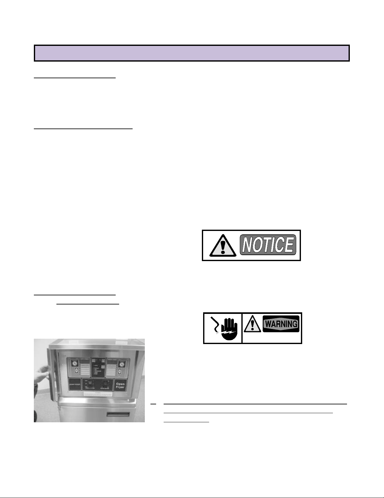
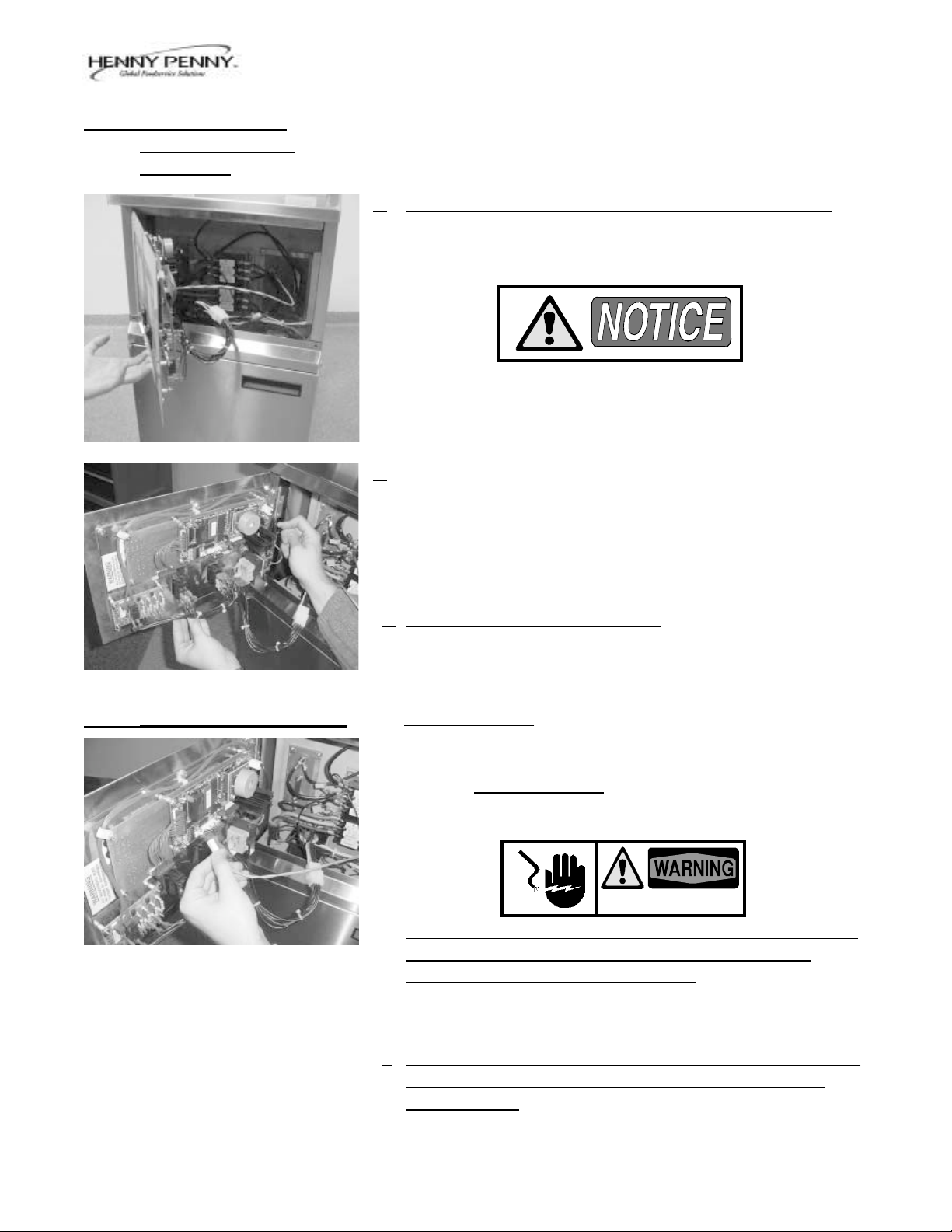
2-3. REMOVING THE
CONTROL PANEL
A continuity light cannot be used to check coils or motors.
To replace parts located inside the fryer, you will need to remove the
control panel. The following steps provide the correct procedure.
SHOCK HAZARD
To avoid electrical shock or property damage, move the
power switch to “OFF” and disconnect main circuit breaker,
or unplug cord at wall receptacle.
1. Remove the decorative strips, located on each side of the control
panel, by removing the screw located on the bottom of each
decorative strip.
593
2-1
2-3. REMOVING THE
CONTROL PANEL
(Continued)
Model OE-100
2. Control panel swings out, hinged on the left side of the panel.
When completely removing control panel, all wiring must be
unplugged from control panel. Be sure to mark wires before
removing.
3. Pulling down on the spring loaded hinge pin, pull control panel
straight out to completely remove.
4. Install control panel in reverse order.
2-4. TEMPERATURE PROBE The temperature probe determines the shortening temperature. If a
malfunction does occur, an E6 will be displayed on the digital readout.
Turn unit to OFF position, then back to COOK position. If E6 is still
displayed, the temperature probe must be replaced by following these
steps:
SHOCK HAZARD
To avoid electrical shock or property damage, move power
switch to “OFF” position and disconnect main circuit
breaker, or unplug cord at receptacle.
1. Drain the shortening from frypot.
2. Remove the decorative strips, located on each side of the control
panel, by removing the screw located on the bottom of each
decorative strip, and let control panel swing out.
593
2-2
Model OE-100
2-4. TEMPERATURE PROBE
(Continued)
4. Unplug electrical wires from control panel board that are attached
to temperature probe.
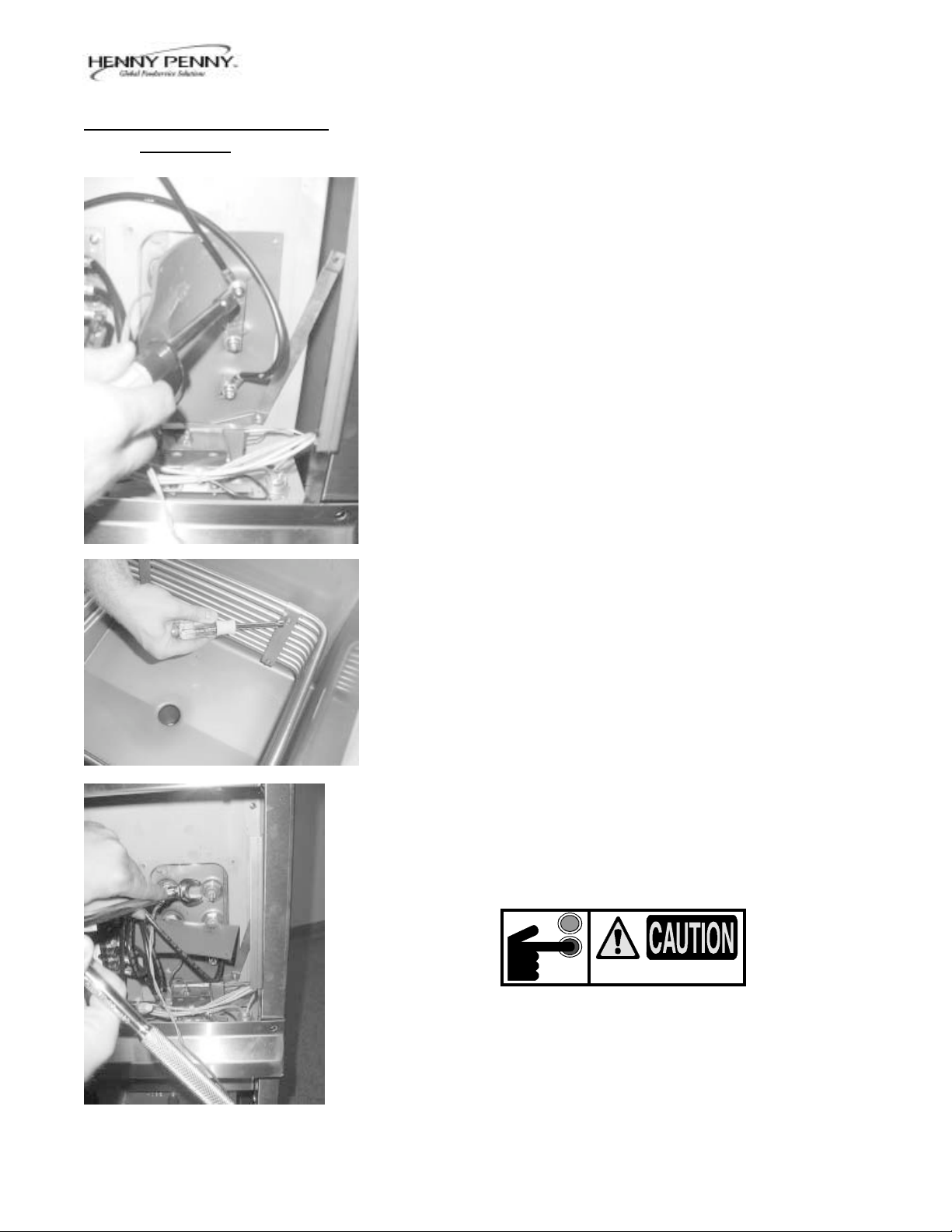
5. Using a 1/2" wrench, loosen screw nut from pot fitting and pull
temperature probe bulb straight out from pot fitting.
6. Install new temperature probe, making sure the temperature
probe extends through pot wall, up to the outer diameter of the
heating element.
Care must be taken not to extend the temperature probe
beyond this point or damage to probe could result.
Also, when installing new temperature probe, you must use
a new locking ferrule in screw nut. Snug screw nut up and
tighten 1/4 turn past this point. Do not overtighten screw
nut, or damage to probe could result.
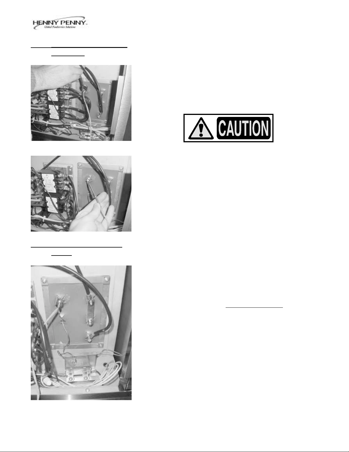
2-5. HIGH TEMPERATURE
LIMIT
The high temperature limit is a manual reset device which senses the
temperature of the shortening. If the shortening temperature exceeds
the safe operating limit, the high temperature limit opens and shuts off
the heat to the frypot.
The high limit light then illuminates and the high temperature limit must
be manually reset.
Disconnect the two wires from the high temperature limit. Check for
continuity between the two terminals after resetting the high limit. If the
circuit is open, replace the high limit following these procedures. If the
circuit is closed, the high limit is not defective. Reconnect the two
electrical wires.
1091
2-3
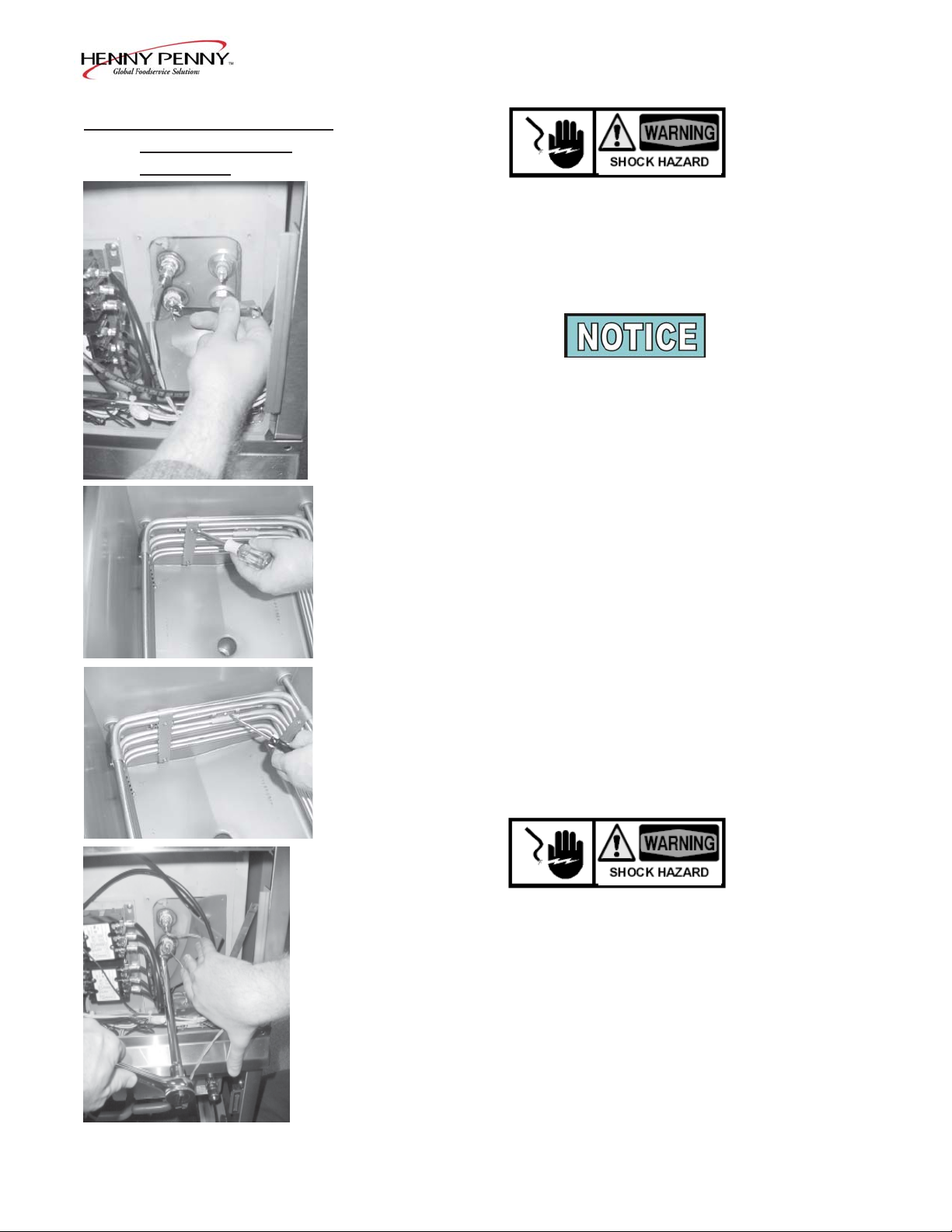
2-5. HIGH TEMPERA TURE
LIMIT CONTROL
(Continued)
Model OE-100
Before following these steps, place POWER switch in the
OFF position and unplug the power cord or open the wall
circuit breaker.
1. If the tube is broken or cracked, the control will open, shutting off
electrical power. The control cannot be reset.
Use replacement high limit, part no. 16337, 420 degree.
2. Drain shortening from the frypot.
3. Remove control panel per Section 2-3.
4. Remove the retainer securing the silicone gasket.
5. Loosen small inside screw nut on capillary tube.
6. Remove capillary bulb from bulb holder inside the frypot.
7. Straighten the capillary tube.
8. Remove larger outside nut that threads into pot wall.
9. Remove the two nuts that hold the high limit bracket from control
panel area.
10. Lift defective control from control panel area.
11. Insert new control and replace nuts to bracket.
12. Uncoil capillary line, starting at capillary tube, and insert through
frypot wall.
To avoid electrical shock or other injury, the capillary line
must run under and away from all electrical power wires
and terminals. The tube must never be in such a position
where it could accidentally touch the electrical power
terminals.
409
13. Carefully bend the capillary bulb and tube toward bulb holder on
heating elements.
14. Slip capillary bulb into bulb holder located on heating elements.
Pull excess capillary line from pot and tighten nut into frypot wall.
2-4
Model OE-100
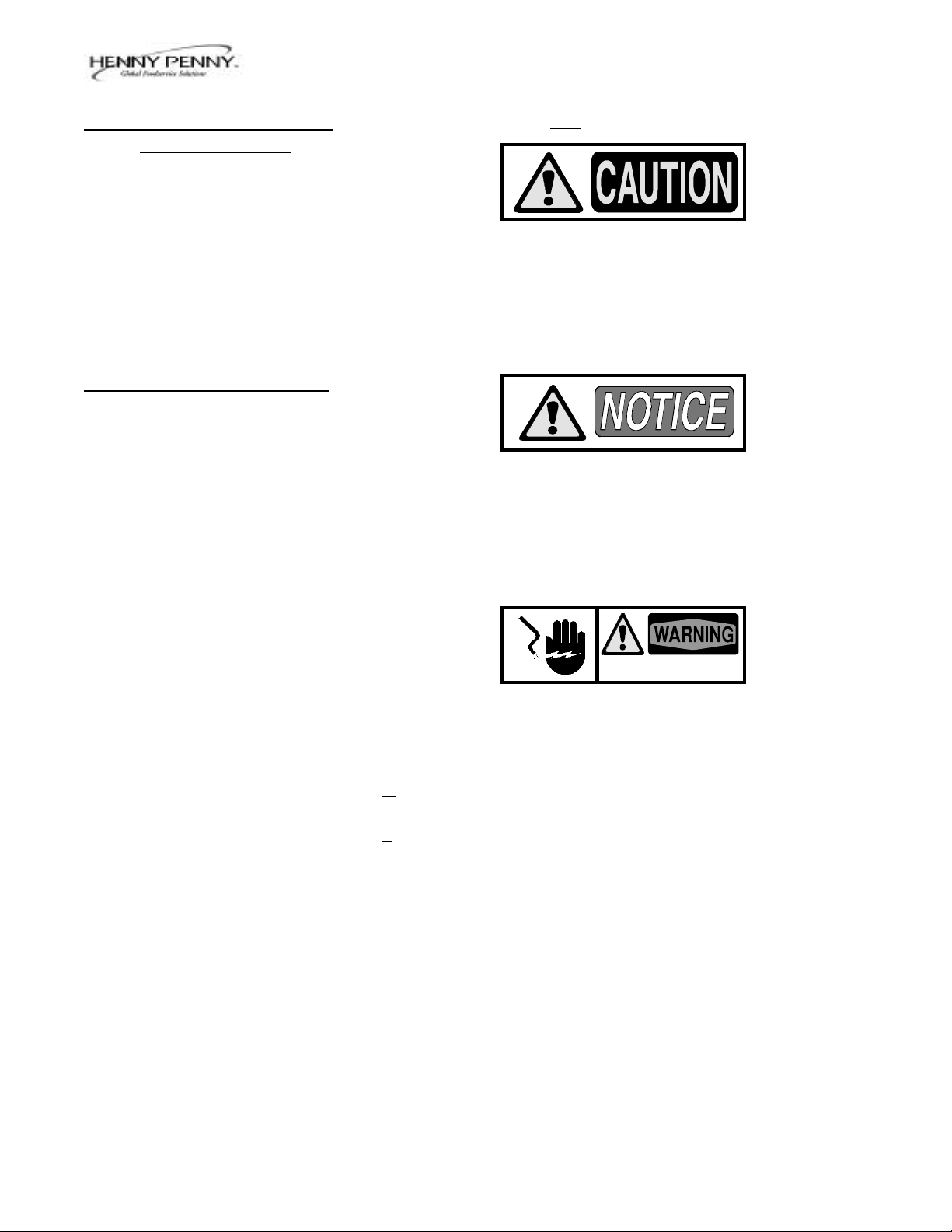
2-5. HIGH TEMPERATURE
LIMIT (Continued)
2-6. HEATING ELEMENTS
15. With excess capillary tube pulled out, tighten smaller nut.
Do not overtighten nut or damage to capillary tube may
result.
16. Replace front panel.
17. Refill with shortening.
Heating elements are available for 208 and 480 voltage.
Check the data plate to determine the correct voltage.
If the shortening's temperature recovery is very slow or at a slower
rate than required, this may indicate defective heating element(s). An
ohmmeter will quickly indicate if the elements are shorted or open.
593
SHOCK HAZARD
To avoid electrical shock or property damage, move the
power switch to “OFF” and disconnect main circuit breaker,
or unplug cord at wall receptacle.
1. Remove the control panel. Refer to Section 2-3.
2. Perform an ohm check on one element at a time, with wires
disconnected from element. If the resistance is not within tolerance, replace the element.
Resistance
Voltage Wattage in Ohms (Cold)
480 7333 27.5
415 7333 6.9
380 7333 18.8
240 7333 6.9
208 7333 5.6
480 4500 51.2
415 4500 11.75
240 4500 11.75
208 4500 9.61
2-5
Model OE-100
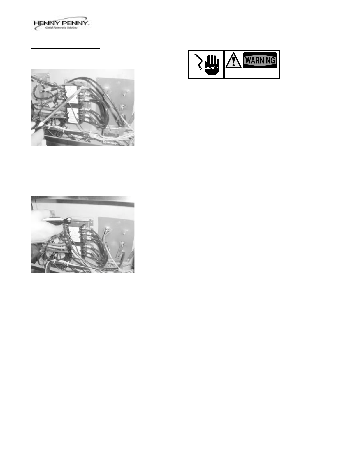
2-6. HEATING ELEMENTS
(Continued)
Replacement
1. Drain the shortening from the frypot.
2. Remove the heating element wire from the terminals by removing
the nuts and washer. Label each so it can be replaced in the same
position on the new element.
3. Remove the retainer securing the silicone gasket.
4. Loosen the bolts on the four element spreaders.
5. Slide the element spreaders to the center of the heating element.
6. Remove the brass nuts (4) and washers (3) which secure the ends
of the elements through the frypot wall.
7. Remove the heating elements from the frypot as a group by lifting
the far end and sliding them up and out toward the rear of the
frypot.
8. Install new heating elements with new "0" rings (2) mounted on
terminal ends and spreaders loosely mounted in the center of the
heating elements.
9. Replace the heating elements, terminal end first, at approximately
450 angle, slipping the terminal ends through the front end of the
frypot.
10. Replace the brass nuts (4) and washers (3) on the heating element
terminals. Tighten the brass nuts to 30 foot pounds of torque.
11. Move the element spreader from the center of the element into a
position which will spread each element apart evenly on all four
sides and tighten.
12. Reconnect the wires to the appropriate terminal as labeled when
they were removed.
13. Replace the front control panel.
14. Connect the power cord to the wall receptacle or close wall
circuit breaker.
TURN OFF POWER
Switch must be in “OFF” position until shortening is
added to frypot or damage to heating elements could result.
15. Replace the shortening in the frypot.
1091
2-6
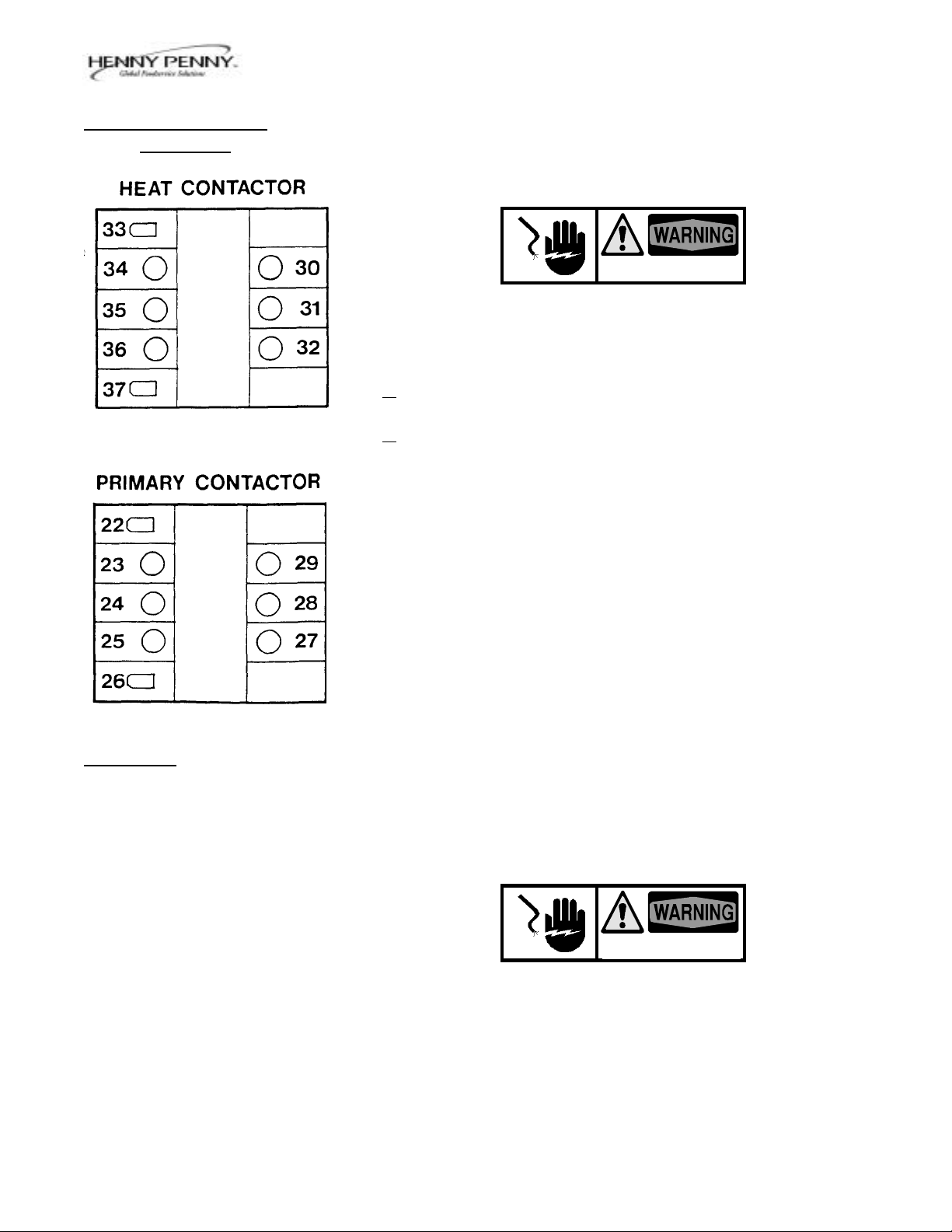
2-7. CONTACTORS
Model OE-100
SHOCK HAZARD
The following tests are performed with the wall circuit
breaker closed and the Power switch in the ON position.
Make connections before applying power, then take readings. Remove power before removing meter leads, or
electrical shock may result.
1. With power applied, increase setpoint temperature setting allowing heat contactor to activate.
Test Points Results
Heat Contactor The voltage
from terminal 34 to 35 should read the
from terminal 35 to 36 same at each
from terminal 34 to 36 terminal.
Test Points Results
Primary Contactor It should
from terminal 27 to 28 correspond to
from terminal 28 to 29 the voltage
from terminal 27 to 29 rating stated on
the data plate.
If either contactor is defective, it must be replaced as follows:
1. Remove electrical power supplied to the fryer by unplugging
or opening the wall circuit breaker.
2. Remove only those wires directly connected to the contactor
being replaced. Label the wires.
3. Remove the two mounting screws on the base plate and
remove contactor.
4. Install the new contactor and tighten the two mounting
screws.
593
5. Connect the labeled wires to their respective positions.
6. Install the control panel.
7. Reconnect power to the fryer and test the fryer for proper
operation.
2-7
Model OE-100
2-7. CONTACTORS
(Continued)
The Henny Penny OE-100 requires two switching contactors. Located on the bottom is the primary contactor with the heat contactor
stacked to the top of the primary. When closed, the primary contactor
completes the heat circuit. It also supplies power to the heat contactor.
SHOCK HAZARD
To avoid electrical shock or property damage, move the
power switch to “OFF” and disconnect main circuit breaker,
or unplug cord at wall receptacle.
1. Remove the control panel. Refer to Section 2-3.
2. Perform a check on the contactor as follows:
Test Points Results
from 23 to 29 open circuit
from 24 to 28 open circuit
from 25 to 27 open circuit
from 30 to 34 open circuit
from 31 to 35 open circuit
from 32 to 36 open circuit
from 22 to 26 ohm reading 415
from 33 to 37 ohm reading 415
2-8. FAN The Henny Penny OE-100 has a fan in the circuit which operates only
when the power switch is in the COOK position. The fan helps keep
the control panel cool by pulling out heat from between the control
panel and frypot.
The replacement of a faulty fan is as follows:
SHOCK HAZARD
To avoid electrical shock or property damage, move the
power switch to “OFF” and disconnect main circuit breaker,
or unplug cord at wall receptacle.
1. Remove control panel per Section 2-3.
593
2-8
2-8. FAN (Continued) 2. Label and disconnect fan motor wires.
3. Remove the four screws, washers, and nuts securing the fan to the
heat shield.
4. Remove the fan from the heat shield.
5. Install the new fan on the heat shield and secure with the four
screws, washers, and nuts.
6. Reconnect the fan motor wires.
7. Install control panel.
Model OE-100
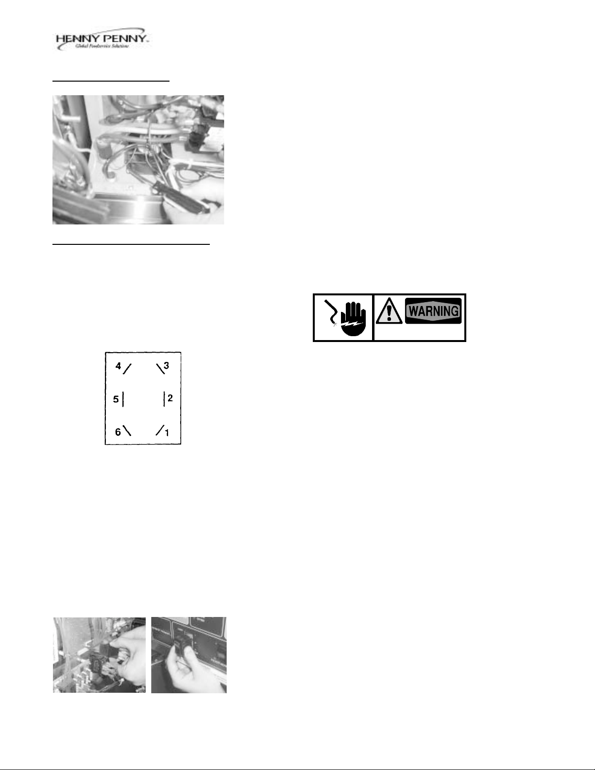
2-9. COOK/PUMP SWITCH
Checkout
The Cook/Pump Switch is a three way rocker switch with a center
"OFF" position. With the switch in the COOK position the fryer will
operate. With the switch in the PUMP position the filter pump will
operate, but the unit will not heat.
SHOCK HAZARD
To avoid electrical shock or property damage, move the
power switch to “OFF” and disconnect main circuit breaker,
or unplug cord at wall receptacle.
1. Remove Control Panel, but leave hinged on unit.
2. Remove and label wires from Cook/Pump Switch.
3. "OFF" Position - should be open circuit anywhere on the switch.
4. "COOK" Position
Check from:
#5 to #6 closed circuit
#1 to #2 closed circuit
593
Replacement
5. "PUMP" Position
Check from:
#4 to #5 closed circuit
#3 to #2 closed circuit
1. With control panel removed and wires off the switch, push in on
tabs on the switch to remove from the panel.
2. Replace with new switch, and reconnect wires to switch following
the wiring diagram.
3. Replace the control panel.
2-9
2-10. FUSES
2-11. DRAIN SWITCH
Model OE-100
SHOCK HAZARD
To avoid electrical shock or property damage, move the
power switch to “OFF” and disconnect main circuit breaker,
or unplug cord at wall receptacle.
Each unit is provided with two fuses to protect the internal circuitry.
These fuses are rated 15 amps at 300 volts. Unthread screw cap to
allow access to fuses located on panel behind door.
SHOCK HAZARD
To avoid electrical shock or property damage, move the
power switch to “OFF” and disconnect main circuit breaker,
or unplug cord at wall receptacle.
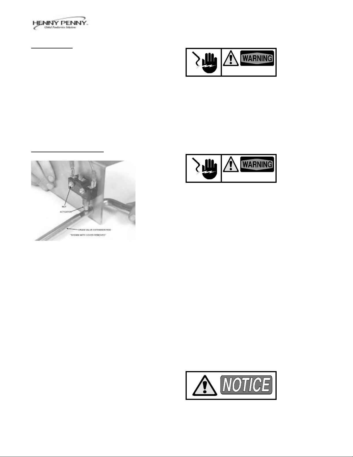
1. A continuity check should be made to determine if the drain
switch is defective. Check between the two outer terminals with
actuator in groove of the drain valve extension rod. Circuit should
be closed. If drain valve extension rod is turned, actuating drain
switch, circuit should be open.
Replacement
1. To replace drain switch, remove two screws and nuts securing
switch and switch cover.
2. Label and disconnect wires.
3. Connect wires to new drain switch.
4. Position actuator and attach drain switch and switch cover with
the two screws and nuts.
5. Test to see if drain valve extension rod actuates the switch.
1091
Listen for click of switch while rotating drain valve rod.
2-10
 Loading...