

Page 1

Henny Penny
Humidified Holding Cabinets
Model HHC-990
Model HHC-992
Model HHC-993
Model HHC-996
Model HHC-997
Model HHC-998
OPERA TOR’S MANUAL
Page 2

Model HHC-990
LIMITED WARRANTY FOR HENNY PENNY APPLIANCES
Subject to the following conditions, Henny Penny Corporation makes the following limited warranties to the
original purchaser only for Henny Penny appliances and replacement parts:
NEW EQUIPMENT: Any part of a new appliance, except lamps and fuses, which proves to be defective
in material or workmanship within two (2) years from date of original installation, will be repaired or replaced
without charge F.O.B. factory, Eaton, Ohio, or F.O.B. authorized distributor. To validate this warranty, the
registration card for the appliance must be mailed to Henny Penny within ten (10) days after installation.
REPLACEMENT PARTS: Any appliance replacement part, except lamps and fuses, which proves to be
defective in material or workmanship within ninety (90) days from date of original installation will be repaired
or replaced without charge F.O.B. factory, Eaton, Ohio, or F.O.B. authorized distributor.
The warranty for new equipment and replacement parts covers only the repair or replacement of the defective
part and does not include any labor charges for the removal and installation of any parts, travel or other expenses
incidental to the repair or replacement of a part.
EXTENDED FRYPOT WARRANTY: Henny Penny will replace any frypot that fails due to manufacturing or
workmanship issues for a period of up to seven (7) years from date of manufacture. This warranty shall not cover
any frypot that fails due to any misuse or abuse, such as heating of the frypot without shortening.
0 TO 3 YEARS: During this time, any frypot that fails due to manufacturing or workmanship issues will be replaced at no charge for parts, labor, or freight. Henny Penny will either install a new
frypot at no cost or provide a new or reconditioned replacement fryer at no cost.
3 TO 7 YEARS: During this time, any frypot that fails due to manufacturing or workmanship issues will be replaced at no charge for the frypot only . Any freight charges and labor costs to install
the new frypot as well as the cost of any other parts replaced, such as insulation, thermal sensors,
high limits, fittings, and hardware, will be the responsibility of the owner.
Any claim must be presented to either Henny Penny or the distributor from whom the appliance was purchased.
No allowance will be granted for repairs made by anyone else without Henny Penny’s written consent. If damage
occurs during shipping, notify the sender at once so that a claim may be filed.
THE ABOVE LIMITED WARRANTY SETS FORTH THE SOLE REMEDY AGAINST HENNY PENNY
FOR ANY BREACH OF WARRANTY OR OTHER TERM. BUYER AGREES THAT NO OTHER REMEDY
(INCLUDING CLAIMS FOR ANY INCIDENTAL OR CONSEQUENTIAL DAMAGES) SHALL BE AVAILABLE.
The above limited warranty does not apply (a) to damage resulting from accident, alteration, misuse, or
abuse; (b) if the equipment’s serial number is removed or defaced; or (c) for lamps and fuses. THE
ABOVE LIMITED WARRANTY IS EXPRESSLY IN LIEU OF ALL OTHER W ARRANTIES, EXPRESS OR
IMPLIED, INCLUDING MERCHANT ABILITY AND FITNESS, AND ALL OTHER WARRANTIES ARE
EXCLUDED. HENNY PENNY NEITHER ASSUMES NOR AUTHORIZES ANY PERSON TO ASSUME
FOR IT ANY OTHER OBLIGA TION OR LIABILITY .
FM05-007-D
Revised 10-13-04
Page 3

Model HHC-990
TABLE OF CONTENTS
Section Page
Section 1. INTRODUCTION
1-1. Humidified Holding Cabinet .................................................................................. 1-1
1-2. Features ................................................................................................................ 1-1
1-3. Proper Care .......................................................................................................... 1-1
1-4. Assistance............................................................................................................. 1-1
1-5. Safety.................................................................................................................... 1-2
Section 2. INSTALLATION
2-1. Introduction ........................................................................................................... 2-1
2-2. Unpacking ............................................................................................................. 2-1
2-3. Location ................................................................................................................ 2-2
2-4. Electrical Connection ............................................................................................ 2-3
2-5. Cabinet Dimensions and W eights ......................................................................... 2-4
2-6. Probe Clip (Optional) ............................................................................................ 2-5
Section 3. OPERATION
3-1. Introduction ........................................................................................................... 3-1
3-2. Operating Controls................................................................................................ 3-1
3-3. Start-Up ................................................................................................................ 3-4
3-4. Operation with Product......................................................................................... 3-5
3-5. Cleaning Procedures............................................................................................. 3-6
Section 4. PROGRAMMING
4-1. Timer Programming .............................................................................................. 4-1
4-2. Clock Set............................................................................................................... 4- 1
4-3. Special Programming ............................................................................................ 4-3
Section 5. TROUBLESHOOTING
5-1. Troubleshooting Guide........................................................................................... 5-1
5-2. Error Codes and Warnings.................................................................................... 5-2
GLOSSARY ......................................................................................................................... G-1
Distributors List - Domestic and International
i 303
Page 4

Model HHC-990
SECTION 1. INTRODUCTION
1-1. HUMIDIFIED HOLDING The Henny Penny humidified holding cabinets are designed
CABINET to keep hot foods moist, while maintaining proper tempera-
ture. The units are electronically controlled for easy use and
for consistent operation.
1-2. FEATURES • Electronically controlled humidity and temperature
• Lift-off doors
• Stainless steel construction
• Easily maintained
• Lift-out tray racks
• Full perimeter magnetic door seals
• Easy access to electrical controls
• Food probe supplied to easily display food temperature
1-3. PROPER CARE As in any unit of food service equipment, the Henny Penny humidi-
fied holding cabinet does require care and maintenance. Requirements for the maintenance and cleaning are contained in this manual
and must become a regular part of the operation of the unit at all
times.
1-4. ASSISTANCE Should you require outside assistance, just call your local indepen-
dent Henny Penny distributor in your area, or call Henny Penny
Corp. 1-800-417-8405 toll free or 1-937-456-8405.
303 1-1
Page 5

Model HHC-990
1-5. SAFETY The Henny Penny Humidified Holding Cabinet has safety
features incorporated. However, to ensure a safe operation,
read and fully understand the proper installation, operation,
and maintenance procedures. The instructions in this manual
have been prepared to aid you in learning the proper procedures. Where information is of particular importance or
safety related, the words WARNING, CAUTION, and
NOTICE are used. Their usage is described below.
SAFETY ALER T SYMBOL is used with DANGER,
W AR NING , or CAUTION which indicates a personal injury
type hazard.
NOTICE is used to highlight especially important information.
CAUTION used without the safety alert symbol indicates
a potentially hazardous situation which, if not avoided, may
result in property damage.
CAUTION used with the safety alert symbol indicates a
potentially hazardous situation which, if not avoided,
may result in minor or moderate injury.
W ARNING indicates a potentially hazardous situation
which, if not avoided, could result in death or serious
injury .
1-2 303
Page 6

Model HHC-990
SECTION 2. INSTALLATION
2-1. INTRODUCTION
Installation of this unit should be performed only by a
qualified service technician.
Do not puncture the skin of the unit with drills or
screws, or component damage or electrical shock
could result.
2-2. UNPACKING The Henny Penny humidified holding cabinet has been
tested, inspected, and expertly packed to ensure arrival
at its destination in the best possible condition.
Note any shipping damage in the presence of the
delivery agent and signed prior to his or her departure.
T o remove the Henny Penny cabinet from carton:
1. Carefully cut banding straps.
2. Lift carton off the unit.
3. Lift the unit off the cardboard padding and skid.
Full-size cabinets weigh approximately 300 lbs.
(136 kg). Care should be taken when lifting unit to
prevent personal injury .
303 2-1
Page 7

Model HHC-990
2-2. UNP ACKING (Continued) 4. Open doors and remove packing from behind racks and
the water pan in the bottom of the unit.
5. Peel off any protective covering from the exterior of the
cabinet.
6. The cabinet is now ready for location and use.
2-3. LOCA TION Place the humidified holding cabinet in an area that allows
the doors to be opened without interference of loading and
unloading product. Also, keep the unit level for proper
operation.
No minimum clearances are required for the rear and
sides of the cabinet.
2-2 303
Page 8

2-4. ELECTRICAL CONNECTION
Model HHC-990
T o avoid electrical shock, the cabinet must be adequately
and safely grounded (earthed) according to local electrical
codes, and this appliance must be equipped with an external circuit breaker which will disconnect all ungrounded
(unearthed) conductors. The main power switch on this
appliance does not disconnect all line conductors.
(FOR EQUIPMENT WITH CE MARK ONLY!)
To prevent electric shock hazard this appliance must be
bonded to other appliances or touchable metal surfaces
in close proximity to this appliance with an equipotential
bonding conductor. This appliance is equipped with an
equipotential lug for this purpose. The equipotential lug
is marked with the following symbol
If the electrical supply to the unit is a cord and plug, then the
electrical receptacle, for the plug, must be easily accessible.Refer
to the table below for the electrical ratings for the HHC-990
series cabinets.
Model Volts,60Hz Phase Amps Watts
HHC-990 120 1 24.0 2880
120 1 22.3 2680
208 1 13.8 2880
240 1 12.0 2876
240 1 11.2 2676
220-240-CE 1 11.6 2792
HHC-993/ 120 1 17.3 2080
HHC-992 208 1 10.0 2080
240 1 8.7 2076
220-240-CE 1 8.3 1992
HHC-996 120 1 27.3 3280
208 1 15.8 3280
240 1 13.7 3276
240 1 16.2 3876
220-240-CE 1 13.3 3192
HHC-997/ 120 1 17.3 2080
HHC-998 120 1 24.0 2880
120 1 22.3 2680
208 1 13.8 2880
240 1 8.7 2076
240 1 12.0 2876
220-240-CE 1 8.3 1992
220-240-CE 1 11.6 2792
1004 2-3
Page 9
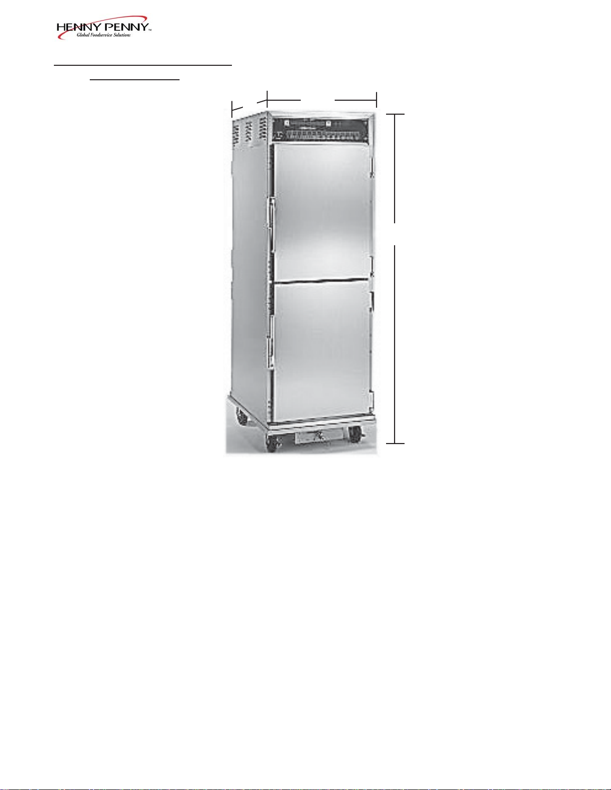
2-5. CABINET DIMENSIONS
AND WEIGHTS
31-3/4” 24-3/4”
(806 mm) (628 mm)
Model HHC-990
72-1/4” (1835 mm)
HHC-990
Unit Height Width Depth Shipping W eight
HHC-993 38” (965 mm) 24-3/4” (628 mm) 31-3/4” (806 mm) 220 lbs (100 kg)
HHC-990 72-1/4” (1835 mm) 24-3/4” (628 mm) 31-3/4” (806 mm) 367 lbs (167 kg)
HHC-992 76” (1930 mm) 24-3/4” (628 mm) 31-3/4” (806 mm) 493 lbs (224 kg)
HHC-998 38” (965 mm) 27-3/4” (705 mm) 31-3/4” (806 mm) 269 lbs (122 kg)
HHC-996 72-1/4” (1835 mm) 27-3/4” (705 mm) 31-3/4” (806 mm) 400 lbs (181 kg)
HHC-997 76” (1930 mm) 27-3/4” (705 mm) 31-3/4” (806 mm) 523 lbs (237 kg)
2-4 303
Page 10

Model HHC-990
2-6. PROBE CLIP (OPTIONAL) The probe clip is an accessory , that may be ordered as an option,
to hold the food probe when not in use.
Remove one of the module screws and mount the probe clip with
that screw . See photo at left.
The food probe is accessed easier if the clip is mounted on
the side of the unit that the door opens. See photo below .
Probe Clip
Mount clip
here.
303 2-5
Page 11
Model HHC-990
SECTION 3. OPERATION
3-1. INTRODUCTION This section provides explanations of all controls, along
with operating procedures and daily maintenance. Read the
Introduction, Installation and Operation Sections before
operating the unit.
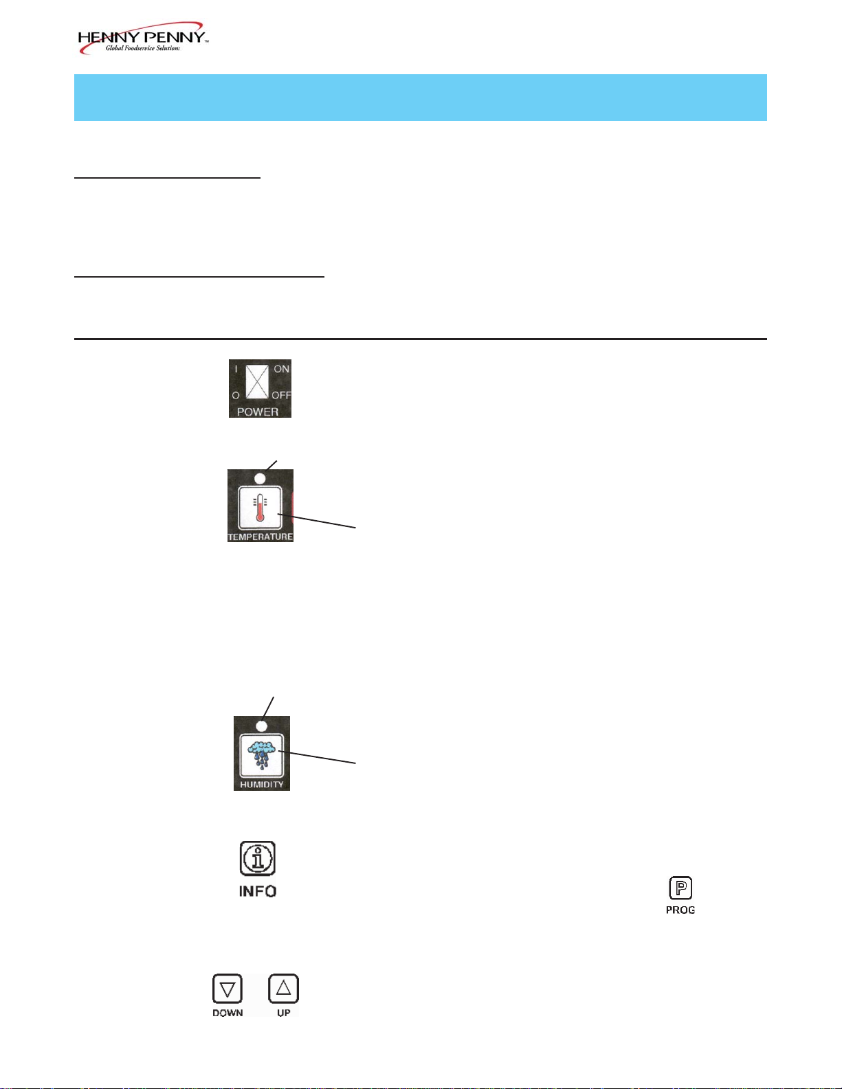
3-2. OPERATING CONTROLS
Fig. Item
No No. Description Function
3-1 1 POWER Switch A rocker switch that sends electrical current to the operating
components when turned on
3-1 2 T emperature LED Lights when the control calls for heat, and the unit should start
heating; it goes out once the temperature inside the cabinet
reaches the programmed temperature setting
Press the TEMPERA TURE Button to set the cabinet temperature
3-1 3 Digital Display Shows the cabinet temperature, humidity settings, and the selec-
tions in the Program Mode; the temperature of the cabinet
is shown by pressing the INFO button; if the temperature
exceeds 300 °F (149°C), the display reads “E-5”, TOO HOT”.
3-1 4 Humidity LED Lights when the control calls for humidity; it goes out once the
humidity inside the cabinet, reaches the programmed humidity
setting
Press the HUMIDITY button to set the relative humidity inside
the cabinet, and to choose between the Proofing and Holding
Modes, when the unit is turned on
3-1 5 Press to view the food probe temperature, cabinet temperature
and humidity , date and time; if pressed in the Program Mode,
shows previous settings; pressing this along with accesses
the Information Mode which has historic information on the
cabinet’ s performance
3-1 6 & 7 Used to adjust the value of the currently displayed setting in
the Program Mode
3-1 303
Page 12

Model HHC-990
3-2. OPERATING CONTROLS
(Continued)
3-1 8 Used to access the Program Modes; once in the Program Mode,
it is used to advance to the next parameter; pressing this along
with accesses the Information Mode
which has historic information on the cabinet’s performance
3-1 9 Food Probe After plugging the food probe into the receptacle, the meat probe
Receptacle can then be inserted into the product and the product temperature
is displayed
3-1 10 Count Down Once a tray of food is placed in the cabinet, the appropriate timer
Timers is pressed, and the time remaining shows in the display above the
timer number; once the timer counts down to zero, the display
flashes “0:00”, and the control beeps; the HHC-990 and 996
have 15 timers, and the HHC-993 and 998 have 5 timers
303 3-2
Page 13

3-2. OPERATING CONTROLS
(Continued)
Control Decal
1 2 3 4 5 6 7 8
Model HHC-990
9
10
Figure 3-1
3-3 303
Page 14

3-3. ST ART-UP
Model HHC-990
Before using the humidified holding cabinet, thoroughly
clean the unit as described in the Cleaning Procedures
Section of this manual.
1. Plug unit into electrical receptacle, or turn on wall circuit
breaker . With the POWER switch turned to OFF the
display shows “POWER OFF.”
With the POWER Switch of f, the display may show
“PURGING”. This means the humidity has reached
95% inside the unit and the fan runs to help drop the
humidity . Once the humidity reaches 92%, “POWER
OFF” again shows in the display .
Slot
Even though POWER switch is OFF it does not disconnect all electrical supplies to the controls.
Unplug power cord, or turn off wall circuit breaker
before servicing any electrical components, or
electrical shock could result.
2. Turn the POWER switch to ON, and the display
shows “PUSH TO PROOF”.
3. If the unit is to be used as a proofer, (80-140o F)
(27-60o C), press the HUMIDITY button within 10
seconds, while thedisplay still shows “PUSH
TO PROOF”. If not, allow unit to heat normally ,
(140o-210o F) (60o-99o C).
4. Open door of unit and pour up to 3 gallons of water
into bottom water pan, (minimum 1 gallon) up to the slot
on the concentration ring. See figure 3-2.
Figure 3-2
Do not overfill the water pan, or water could over
flow and spill onto the floor , and personal injur y
could result.
303 3-4
Page 15

Model HHC-990
3-3. ST ART-UP (Continued) 5. Press the TEMPERATURE button to set the desired
cabinet temperature. While the LED is flashing, press
the UP and DOWN buttons until the desired temperature shows in the display .
6. Press the HUMIDITY button to set the desired cabinet
humidity (OFF to 90%). While the LED is flashing,
press the UP and DOWN buttons until the desired
temperature shows in the display .
7. Allow the unit to preheat for about 1 hour prior to
placing product in the cabinet. This allows the interior
conditions to stabilize.
3-4. OPERATION WITH 1. The LEDs above the TEMPERATURE and HUMIDITY
PRODUCT buttons go out when the desired temperature and
humidity are reached inside the cabinet. Place hot
product on pan and slide pan onto the racks of the
cabinet.
The minimum holding temperature for potentially
hazardous product is 150o F (66o C). Use the food
probe to accurately display food temperature. Also,
the cabinet product load capacity for the full size
units is 375 lbs. (170 kg.), and 125 lb. (57 kg.) for
the half-sized units. V iew the temperature at any
time by pressing .
2. Press the appropriate timer button (1-15), and the
time, (hours:minutes), starts counting down in display .
3. At the end of the timing period, the control beeps, and
“0:00” flashes in display .
A float switch in the water pan senses when the
water level is low and the display shows “WA TER
LEVEL LOW”. Add more water to the water pan.
4. Open the doors only as necessary to load and unload
product. This helps to keep the interior conditions
constant and saves energy.
3-5 303
Page 16

3-5. CLEANING Daily:
PROCEDURES
1. Turn all controls off and disconnect electrical supply .
2. Open doors and remove all trays and racks from unit,
Figure 3-3
3. Wipe interior and exterior of cabinet with damp cloth,
Model HHC-990
T o avoid burns, allow the unit to cool before cleaning.
and take them to a sink to thoroughly clean.Figure 3-3.
soap and water .
Do not use steel wool, other abrasive cleaners or
cleaners/sanitizers containing chlorine, bromine, iodine
or ammonia chemicals, as these will deteriorate the
stainless steel, and glass material, and shorten the life
of the unit.
Do not use a water jet (pressure sprayer) to
clean the unit, or component failure could result.
4. Wipe the control panel with a damp cloth. Do not
splash water around controls.
5. Reinstall racks, and leave a door partially open over
night to allow interior cabinet to thoroughly dry .
303 3-6
Page 17

3-5. CLEANING Weekly:
PROCEDURES (Continued) 1. Remove pans and racks from cabinet.
2. Open drain valve and empty water pan into a shallow
pan or floor drain. See Figure 3-4.
Hot water! Do not place your hand under the
drain while draining the unit. Failure to follow this
Figure 3-4 warning could result in severe burns and injury .
3. Remove concentration ring assembly from water pan.
See Figure 3-5.
Model HHC-990
Concentration ring could be hot! Allow to cool
before removing, or burns could result.
Figure 3-5 4. W ash the concentration ring in a dishwasher or sink.
5. Liberally spray the water pan with a concentrated
deliming agent and let stand for 10 minutes.
To avoid damage to the unit, delime the unit weekly.
6. Scrub the pan with a brush and flush with water.
7. Return concentration ring assembly to the water pan.
8. Reinstall the racks and fill the water pan with water to
the maximum water fill line.
9. Unit is now ready for use.
Monthly:
1. Remove the 2 screws securing the vented panel on the
rear of the module and remove the panel, and clean
vents.
2. Using a cloth or sponge, clean the trough once a
month.
Figure 3-4
3-7 303
Page 18

SECTION 4. PROGRAMMING
This section explains the following programming functions.
• Timer programming
• Clock-set
• Special programming
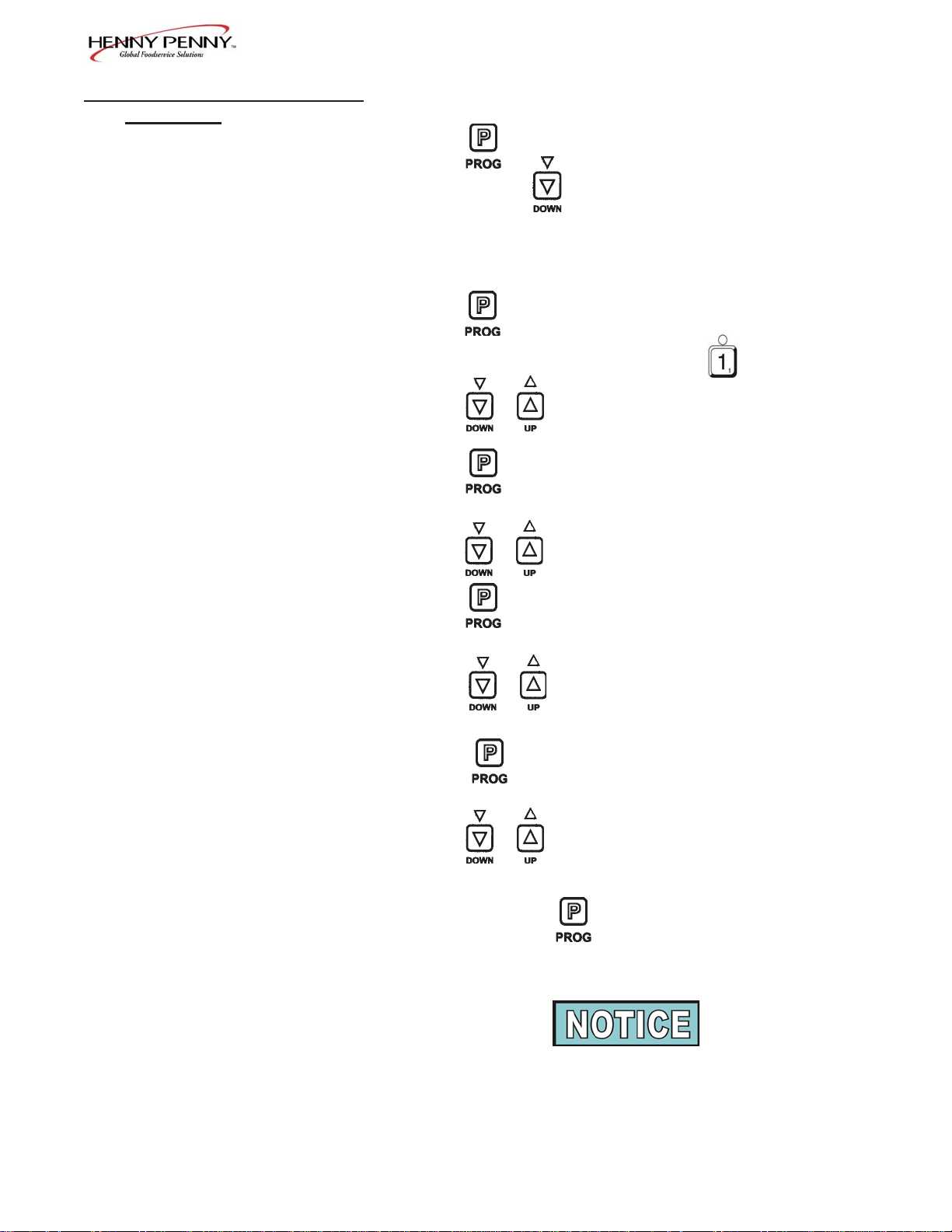
4-1. TIMER PROGRAMMING T o enter the Program Mode:
1. Press and hold for 2 seconds, and “PROG TMRS”
shows in display .
2. After 5 seconds, “ENTER CODE” shows in display .
3. Press , and “PUSH TIMER BUTTON
Model HHC-990
“TO SELECT FOR PROGRAMMING,” followed by
“USE UP AND DOWN TO CHANGE SELECTED
TIMERS,” scrolls through the display .
4. Press the desired timer button (1-15). (More than one can
be programmed at one time).
5. Press to change the selected timer settings.
6. Once timers are set, press and hold the , and new timer
settings become active and normal operation is resumed.
4-2. CLOCK SET 1. Press and hold for 5 seconds, and LEVEL 2, then
(Time-of-day , date, and
day of the week) “CLOCK SET” shows in display .
2. After 5 seconds, “ENTER CODE” shows in display .
3. Press .
4. “CS-1, SET , HOUR”, and the time of day (with the hour
flashing) shows in the display .
5. Press the to change the hours.
303 4-1
Page 19

Model HHC-990
4-2. CLOCK SET 6. Press and “CS-2, SET, MINUTE” shows in the
(Continued)
display , with the minutes flashing.
7. Press to change the minutes.
8. Press and “CS-3, SET, MONTH” shows in the
display , along with the date (month flashing).
9. Press to change the month.
10. Press and “CS-4, SET, DATE” shows in the display ,
with the date flashing.
11. Press to change the date.
12. Press and “CS-5, SET , YEAR” shows in the display ,
with the year flashing.
13. Press to change the year.
14. Press and hold to exit programming.
4-2 303
Page 20

Model HHC-990
4-3. SPECIAL PROGRAMMING This mode allows you to program the following:
SP-1 • Fahrenheit/celsius
SP-2 • Lock/unlock
SP-3 • Air temperature setpoint
SP-4 • Humidity setpoint
SP-5 • Proof air temperature
SP-6 • Proof humidity setpoint
SP-7 • Out of water tripp point
SP-8 • Clean water pan setpoint
SP-9 • System intialization
SP-10 • Audio volume
SP-11 • Audio tone
SP-12 • Audio effects
SP-13 • Language options
SP-1 Fahrenheit/Celsius 1. Press and hold the until “LEVEL 2”, then “CLOCK SET”
shows in the display .
2. Press again, then “SP PROG” shows in display .
3. After 5 seconds, “ENTER CODE” shows in display .
4. Press and “SP-1, TEMP, UNITS” and
“oF”or “oC” shows in the display .
5. Press the to change temperature units.
SP-2 Lock/Unlock 6. Press and “SP-2, LOCK/UNLOCK PROGRAMMING’
shows in display , along with either “LOCK” or “UNLOCK”.
7. Press to change lock the programming or unlock the
programming.
SP-3 Air T emperatur e Setpoint 8. Press and “SP-3, AIRTEMP SETPOINT ,” and the
preset cabinet temperature shows in display .
9. Press to change the air temperature setpoint,
140o F (60o C) minimum, 210o F (99o C) maximum.
303 4-3
Page 21

Model HHC-990
4-3. SPECIAL PROGRAMMING
(Continued)
SP-4 Humidity Setpoint 10. Press and “SP-4, HUMIDITY SETPOINT,” and the
preset humidity setpoint shows in display .
11. Press to change the humidity setpoint, 0 to 90%.
SP-5 Proof Air T emperature 12. Press and “SP-5, PROOF AIR TEMP,” and the preset
Setpoint
proofing air temperature shows in display .
13. Press to change the proofing temperature,
80o F (27o C) minimum, 140o F (60o C) maximum.
SP-6 Proof Humidity Setpoint 14. Press and “SP-6, PROOF HUMIDITY SETPOINT ,”
and the preset proofing humidity shows in display .
15. Press to change the proofing humidity, 10 to 90%.
SP-7 Out of W ater T rip Point 16. Press and “SP-7, OUT OF WATER TRIP POINT” and
the preset trip point temperature shows in display . If the float
switch fails, the trip point temperature is the water pan temperature at which the control senses the water pan is out of water .
W e recommend a trip point temperature of 450o F (232o C).
17. Press to change the out-of-water trip point.
SP-8 Clean W ater Pan Setpoint 18. Press and “SP-8, CLEAN W ATER PAN SETPOINT,”
and the preset temperature, at which the controls senses that
the water pan needs cleaned of lime, shows in the display .
W e recommend a setpoint temperature of 425o F (218o C).
19. Press to change the setpoint.
4-4 303
Page 22
Model HHC-990
4-3. SPECIAL PROGRAMMING
(Continued)
SP-9 System Initialization 20. Press and “SP-9, DO SYSTEM INIT” shows in display.
(Factory Settings)
21. Press and hold until the display counts down from 3, and
the display flashes “-INIT -,” then “INIT*DONE”. This completes the initialization, and sets the control to factory settings.
SP-10 Audio V olume 22. Press and “SP-10, AUDIO VOLUME,” and the volume
setting (1 to 10) shows in display . Press
to test volume.
23. Press to change the volume.
SP-1 1 Audio T one 24. Press and “SP-11, AUDIO TONE -(Hz)-” and the tone
setting (50 to 2000) shows in display .
25. Press to change the tone setting.
SP-12 Audio Effects 26. Press and “SP-12, AUDIO EFFECT” and the effect
setting (0 to 3) shows in display .
27. Press to change the pattern of the tone.
SP-13 Language Options 28. Press and “SP-13, LANGUAGE,” and the preset
language shows in the display .
29. Press to change to English, French, German,
Spanish, or Portuguese.
30. Press and hold the button anytime during programming to
exit the Special Programming Mode.
For more information on the other settings of Special
Programming, call your local Henny Penny distributor in your
area, or call Henny Penny Corp. at 1-800-417-8405 or
1-937-456-8405.
303 4-5
Page 23

SECTION 5. TROUBLESHOOTING
5-1. TROUBLESHOOTING GUIDE
PROBLEM CAUSE CORRECTION
Product not • Doors left open • Keep doors closed except
holding temperature to load and serve product
• Product held too long • Hold product only for recommended times
• Control temperature set too low • Increase air temperature
(SP-3) in Special Program Mode
• Door gasket torn or worn • Replace bad door gaskets
Model HHC-990
Cabinet steaming • Humidity setpoint too high • Decrease humidity setpoint
product soggy (SP-4) in Special Program Mode
Product dry • Humidity setpoint too low • Increase humidity setpoint
(SP-4) in Special Program Mode
• No water in pan • Pour water in water pan
Unit not heating • Blown fuse • Change15 amp fuse
Unit not reaching set • Doors left open • Keep doors closed except
temperature to load and serve product
• Door gasket torn or worn • Replace bad door gaskets
More detailed troubleshooting information is available in the T echnical Manual, available at www .hennypenny .com,
or 1-800-417-8405 or 1-937-456-8405.
5-1 703
Page 24

Model HHC-990
5-2. ERROR CODES AND The display shows the following error codes and warnings when a
WARNINGS fault is detected, along with an alarm sound. Both the heat and
humidity systems shut down, except when specified otherwise.
Display Cause Panel Board Correction
“E-4 CPU TOO HOT” • Control board too hot;
unit overheating or
louvers clogged
“E-5 AIR TEMP TOO HOT” • Faulty relay, PC board,
or air probe
“E-54A CPU TEMP SENSOR • Faulty PC board
OPEN”
• Turn switch to OFF position, then back to
ON; if display still shows “E-4”, the PC
board is getting too hot; clean louvers and
check cooling fan; if cooling fan is not
working, have it replaced; once panel
cools down, the controls should return to
normal; if “E-4” persists, have the PC
board replaced
• Turn switch to OFF position, then back to
ON; if display shows “E-5”, the heating
circuits and temperature probe should be
checked; once the unit cools down, the
controls should return to normal; if “E-5”
persists, have the PC board replaced
• Turn switch to OFF position, then back to
ON; if display shows “E-54A”, the
control should be re-initialized (see Programming Section); if the error code
persists, have PC board replaced
“E-54B CPU TEMP SENSOR • Faulty PC board
SHOR TED”
• Turn switch to OFF position, then back to
ON; if display shows “E-54B”, the
control should be re-initialized (see Programming Section); if the error code
persists, have PC board replaced
“E-6A AIR TEMP SENSOR • Faulty air probe
F AILED OPEN”
• Turn switch to OFF position, then back to
ON; if the display shows “E-6”, the
temperature probe should be checked;
once the temperature probe is repaired, or
replaced, the controls should return to
normal; if “E-6” persists, have the PC
board replaced
303 4-7
Page 25

5-2. ERROR CODES AND
WARNINGS (Continued)
Display Cause Panel Board Correction
“E-6B AIR TEMP SENSOR • Faulty air temperature
FAILED SHORTED” probe
Model HHC-990
• Turn switch to OFF position, then back to
ON; if the display shows “E-6”, the
temperature probe should be checked;
once the temperature probe is repaired, or
replaced, the controls should return to
normal; if “E-6”persists, have PC board
replaced
“E-12A WATER HEATER • Faulty water
SENSOR FAILED heater probe
OPEN”
“E-12B W ATER HEATER • Faulty water
SENSOR FAILED heater probe
CLOSED”
“E-17 HUMI DITY SEN SOR • Faulty humidity sensor
FAILED”
• Turn switch to OFF position, then back to
ON; if the display shows “E-12A”, the
water heater should be checked and
repaired or replaced (the water heater
probe is built into the water heater); the
controls should return to normal; if
“E-12A” persists, have PC board replaced
• Turn switch to OFF position, then back to
ON; if the display shows “E-12B”, the
water heater should be checked and
repaired or replaced (the water heater
probe is built into the water heater); the
controls should return to normal; if
“E-12B” persists, have PC board replaced
• Turn switch to OFF position, then back to
ON; if the display shows “E-17”, the
humidity sensor should be checked;
once the humidity sensor is repaired, or
replaced, the controls should return to
normal; if “E-17” persists, have PC board
replaced
“E-18 NO WATER, FLOAT • Float switch stuck or
SWITCH FAILED” faulty; faulty relay
(stuck on);water pan
needs cleaned;
loose or faulty water
heater sensor; acorn nuts
on water heater cover
loose, or water heater
insulation missing or
damaged
A humidity error only shuts down the humidity system. If a humidity error occurs, and you want to
use the cabinet without humidity , turn the humidity off by following the directions for SP-4, Humidity
Setpoint, in Special Programming Section of this manual. Once the setpoint is off, the alarm stops,
but the error code shows in display . (Includes “E-12A”, “E-12B”, “E-17” and “E-18”).
4-8 804
• Turn switch to OFF position, then back to
ON; if the display shows “E-18”, check
and clean float switch; clean water pan;
have relay and water heater sensor
checked and replace if necessary; tighten
acorn nuts on water heater cover; make
sure 2 complete pieces of insulation are
under the water heater cover; if “E-18”
persists, have PC board replaced
Page 26

5-2. ERROR CODES AND
WARNINGS (Continued)
Display Cause Panel Board Correction
Model HHC-990
“E-41 SYSTEM DA T A LOST” • Memory scrambled
“E-46 DA T A SA VE F AILED” • Memory scrambled
“E-80 VENT STUCK OR • V ent on rear of module
BAD SWITCH” stuck or faulty vent
activation switch
“PLEASE DE-LIME • Water pan needs
W ATER P AN” cleaned
• Turn switch to OFF position, then back to
ON; if the display shows “E-41”, the
control should be re-initialized (see Programming Section); if “E-41”persists, have
PC board replaced
• Turn switch to OFF position, then back to
ON; if the display shows “E-46”, the
control should be re-initialized (see Programming Section); if “E-46”persists, have
PC board replaced
• Check vent on rear of module for obstructions, or have vent activation switch
replaced
• Follow the weekly cleaning procedures;
this warning will not shut down the heat
or humidity; if “PLEASE DE-LIME
W ATER PAN” persists, have PC board
replaced
“W ATER LEVEL LOW , PLEASE” • W ater pan low on water
or empty
• Fill water pan, in bottom of unit, to the
maximum water fill mark; this warning
won’t shut down the heat or humidity
303 4-8
Page 27

Model HHC-990
G L O S S A R Y
HENNY PENNY HOLDING CABINETS
air temperature probe a round device located inside the cabinet that measures the inside air
temperature and sends that information to the control panel
concentration ring assembly a metal assembly located in the water pan in the bottom of the unit that
helps keep an even humidity level inside the cabinet
clean water pan setpoint a preset temperature at which a sensor warns the operator that the water pan
has excessive lime deposits
control panel the components that control the operating systems of the unit; the panel is
located on the top front surface of the cabinet
deliming agent a cleaner used to remove lime deposits in the water pan
drain valve a device that lets the water drain from the water pan into a shallow pan on
the floor; the valve should be closed while the unit is in use if humidity is
desired
float switch a device that senses low water levels in the water pan
food probe a sensor located outside the cabinet that, when inserted into the product,
communicates the temperature of the product to the control panel
food probe receptacle the connection where the food probe is inserted in order to communicate
with the control panel
humidity sensor a device that measures the percentage of humidity inside the cabinet during
use
humidity setting a preset moisure level at which the cabinet operates; this setting is
programmed at the factory but can be changed in the field
LED an electronic light on the control panel
minimum holding temperature the lowest temperature at which a food product can be safely held for
human consumption
module the removeable top part of the cabinet that contains all of the operating
system
out of water trip point a preset temperature at which a sensor warns the operator that the water
pan needs refilled
parameters a preset group of setpoints designed for holding specific food products at
certain temperature and humidity levels
power switch the ON/OFF switch that sends electricity to the unit’s operating systems;
this switch does not disconnect the electrical power from the wall to the unit
pressure sprayer a device that shoots a stream of water under pressure; this device should
NOT be used to clean a holding cabinet
G-1 303
Page 28

Model HHC-990
probe clip a metal holder that attaches to the outside of the control panel to hold the
food probe when not in use; the clip is an optional accessory
product load capacity the highest recommended number of pounds/kilograms of food product that
can be safely held in the cabinet
proof function a program used for allowing bread to rise
relative humidity the humidity level inside the cabinet
setpoint a preset temperature or humidity; the setpoint is a programmable feature
system initialization a programming process that resets factory settings
temperature setting a preset temperature up to which the cabinet will heat; this setting is
programmed at the factory but can be changed in the field
vent activation switch an automatic control that opens and closes the vent on the rear of the
cabinet to maintain the preset humidity level
vented panels openings on the cabinet that allow air access on the sides and rear of the
module
water fill line the line marked on the inside of the water pan that shows the maximum
water level to prevent overflow onto the floor
water heater sensor a part in the water heater that sends a message to the controls when the
water pan is limed up or empty
water jet a device that shoots a stream of water under pressure; this type of device
should NOT be used to clean a holding cabinet
water pan the area in the cabinet that holds water for creating humidity inside the
cabinet
303 G-2
 Loading...