

Page 1
OPERATOR’S
MANUAL
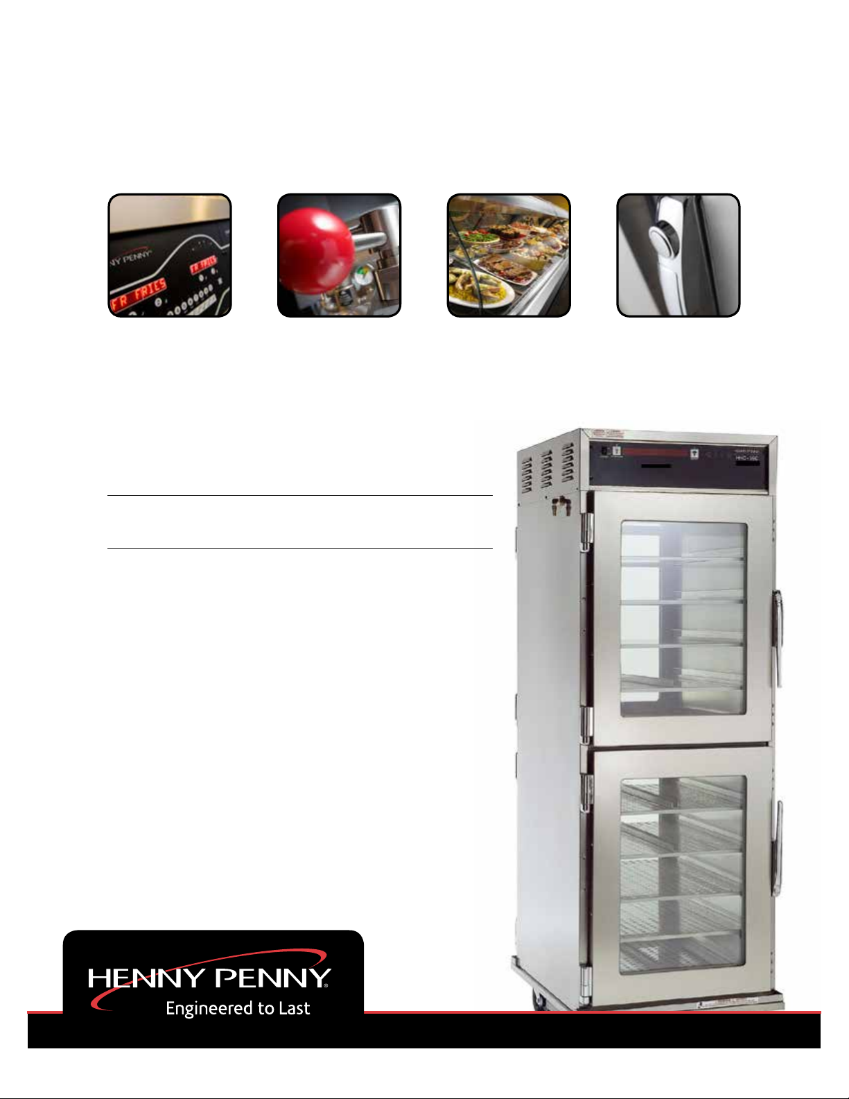
HEATED EXPRESS CABINET
MODEL
HHC-980
HHC-983
REGISTER WARRANTY ONLINE AT WWW.HENNYPENNY.COM
Page 2

Page 3

Model HHC-980/983
TABLE OF CONTENTS
Section Page
Section 1. INTRODUCTION
1-1. Humidified Holding Cabinet ........................................................................................ 1-1
1-2. Features....................................................................................................................... 1-1
1-3. Proper Care ................................................................................................................. 1-1
1-4. Assistance ................................................................................................................... 1-1
1-5. Safety .......................................................................................................................... 1-2
Section 2. INSTALLATION
2-1. Introduction.................................................................................................................. 2-1
2-2. Unpacking ................................................................................................................... 2-1
2-3. Location....................................................................................................................... 2-2
2-4. Electrical Connection................................................................................................... 2-2
2-5. W ater Supply Connection ............................................................................................ 2-3
2-6. Cabinet Dimensions and W eights ................................................................................ 2-4
2-7. Mounting HHC-983 on Stand...................................................................................... 2-5
Section 3. OPERATION
3-1. Introduction.................................................................................................................. 3-1
3-2. Operating Controls ...................................................................................................... 3-1
3-3. Start-Up....................................................................................................................... 3-3
3-4. Operation with Product ............................................................................................... 3-4
3-5. Cleaning Procedures ................................................................................................... 3-4
Section 4. PROGRAMMING
4-1. Introduction.................................................................................................................. 4-1
4-2. Hidden Buttons ............................................................................................................ 4-1
4-3. Clock Set ..................................................................................................................... 4-1
4-4. Special Programming................................................................................................... 4-3
Section 5. TROUBLESHOOTING
5-1. Troubleshooting Guide ................................................................................................. 5-1
5-2. Error Codes and Warnings .......................................................................................... 5-2
GLOSSARY ......................................................................................................................... G-1
Distributors List - Domestic and International
i 804
Page 4

Model HHC-980/983
Page 5

Model HHC-980/983
SECTION 1. INTRODUCTION
1-1. HUMIDIFIED HOLDING The Henny Penny humidified holding cabinets are designed
CABINET to keep hot foods moist, while maintaining proper tempera-
ture. The units are electronically controlled for easy use and
for consistent operation.
As of August 16, 2005, the W aste Electrical and Electronic Equipment directive went into effect for the European Union. Our
products have been evaluated to the WEEE directive. W e have
also reviewed our products to determine if they comply with the
Restriction of Hazardous Substances directive (RoHS) and have
redesigned our products as needed in order to comply . T o continue
compliance with these directives, this unit must not be disposed as
unsorted municipal waste. For proper disposal, please contact
your nearest Henny Penny distributor .
1-2. FEATURES • Electronically controlled humidity and temperature
• Double-paned glass, lift-off doors
• Stainless steel construction
• Easily maintained
• Lift-out tray racks
• Full perimeter magnetic door seals
• Easy access to electrical controls
• Automatic water-fill
1-3. PROPER CARE As in any unit of food service equipment, the Henny Penny humidi-
fied holding cabinet does require care and maintenance. Requirements for the maintenance and cleaning are contained in this manual
and must become a regular part of the operation of the unit at all
times.
1-4. ASSISTANCE Should you require outside assistance, just call your local indepen-
dent Henny Penny distributor in your area, or call Henny Penny
Corp. 1-800-417-8405 toll free or 1-937-456-8405.
107 1-1
Page 6

Model HHC-980/983
1-5. SAFETY The Henny Penny humidified holding cabinet has safety
features incorporated. However, to ensure a safe operation,
read and fully understand the proper installation, operation,
and maintenance procedures. The instructions in this manual
have been prepared to aid you in learning the proper procedures. Where information is of particular importance or
safety related, the words NOTICE, CAUTION, and
WARNING are used. Their usage is described below.
SAFETY ALER T SYMBOL is used with DANGER,
W ARNING , or CAUTION which indicates a personal injury
type hazard.
NOTICE is used to highlight especially important information.
CAUTION used without the safety alert symbol indicates
a potentially hazardous situation which, if not avoided, may
result in pr operty damage.
CAUTION used with the safety alert symbol indicates a
potentially hazardous situation which, if not avoided,
may result in minor or moderate injury.
W ARNING indicates a potentially hazardous situation
which, if not avoided, could result in death or serious
injury.
1-2 203
Page 7

Model HHC-980/983
SECTION 2. INSTALLATION
2-1. INTRODUCTION
Installation of this unit should be performed only by a
qualified service technician.
Do not puncture the unit with any objects such as
drills or screws, or component damage or electrical
shock could result.
2-2. UNPACKING The Henny Penny humidified holding cabinet has been
tested, inspected, and expertly packed to ensure arrival
at its destination in the best possible condition.
Any shipping damage should be noted in the presence
of the delivery agent and signed prior to his or her
departure.
T o remove the Henny Penny cabinet from carton:
1. Carefully cut banding straps.
2. Lift carton off the unit.
3. Lift the unit off the cardboard padding and skid.
T ake care when moving the unit to pr event personal
injury. Full-size cabinets weigh about 300 lbs.
(136 kg).
503 2-1
Page 8

Model HHC-980/983
2-2. UNPACKING
(Continued)
2-3. LOCA TION
2-4. ELECTRICAL
CONNECTION
4. Open doors and remove packing from behind racks and
the water pan in the bottom of the unit.
5. Peel off any protective covering from the exterior of the
cabinet.
6. The cabinet is now ready for location and use.
Place the humidified holding cabinet in an area that allows
the doors to be opened without interference of loading and
unloading product. Also, keep the unit level for proper
operation.
No minimum clearances are required for the rear and sides
of the cabinet.
T o avoid electrical shock, the cabinet must be adequately
and safely grounded (earthed) according to local electrical
codes, and this appliance must be equipped with an external circuit breaker which will disconnect all ungrounded
(unearthed) conductors. The main power switch on this
appliance does not disconnect all line conductors.
(FOR EQUIPMENT WITH CE MARK ONL Y!)
T o prevent electric shock hazard this appliance must be
bonded to other appliances or touchable metal surfaces in
close proximity to this appliance with an equipotential
bonding conductor . This appliance is equipped with an
equipotential lug for this purpose. The equipotential lug is
marked with the following symbol
If the electrical supply to the unit is a cord and plug, then the
electrical receptacle, for the plug, must be easily accessible.
Refer to the table below for the electrical ratings for the
HHC-980 and 983.
Model Volts Phase Amps Watts
HHC-980 208 1 13.8 2880
240 1 12.0 2876
220-240-CE 1 11.6 2792
HHC-983 120 1 17.3 2080
220-240-CE 1 8.3 1992
2-2 1004
Page 9

Model HHC-980/983
2-5. WATER SUPPL Y The automatic water-fill system requires a 1/4 inch, maximum
CONNECTION 100 psi (690 kPa), water connection. A water conditioner or filter ,
and a shut-off valve in the supply line is recommended.
Follow these steps when making the water supply connection:
1. Flush incoming water line.
2. Using pipe joint compound on the threads, screw the brass
elbow into the fitting on the left side the cabinet. Using a 1 inch
wrench, secure the fitting nut while tightening the elbow .
Figure 2-1 Figure 2-1.
3. Connect 1/4 inch tubing to the female quick-disconnect fitting,
supplied with the cabinet. Figure 2-2
4. Attach female quick-disconnect to the male quick-disconnect
on the elbow .
Figure 2-2
This unit as manufactured requires the installation of an appropriate back-siphoning device (as per National Plumbing Code
ASA-A40:8-1955) to be connected to the water inlet line.
This device to be connected in accordance with basic plumbing code of the Building Officials and Code Administrators
International, Inc. (BOCA), and the Food Service Sanitation
Manual of the Food and Drug Administration (FDA).
107 2-3
Page 10

2-6 CABINET DIMENSIONS
AND WEIGHTS
Model HHC-980/983
31-3/4” 24-3/4”
(806 mm) (628 mm)
31-3/4” 24-3/4”
(806 mm) (628 mm)
38”(w/casters)
(965 mm)
72-1/4”
(1835 mm)
59”
(1499 mm)
or
68”
(1727 mm)
HHC-980 HHC-983 w/Stand
Unit Height Width Depth Shipping Weight
HHC-983 38” (965 mm) 24-3/4” (628 mm) 31-3/4” (806 mm) 220 lbs (100 kg)
HHC-980 72-1/4” (1835 mm) 24-3/4” (628 mm) 31-3/4” (806 mm) 367 lbs (167 kg)
T wo HHC-983 stands are available. One gives the total height of 59 inches (1499 mm), and a
taller version, gives the total height of 68 inches (1727 mm).
2-4 203
Page 11

2-7. MOUNTING HHC-983
ON STAND
Model HHC-980/983
1. Unpack the humidified holding cabinet stand (HHS) and
stand upright. Figure 2-3.
Mounting Plates
Figure 2-3
Figure 2-4
2. Unpack the HHC-983.
3. Lift doors off of the HHC-983 to make it easier to lift.
4. Lift the HHC-983 and set it on the posts of the HHS,making
sure the locking casters are towards the front of the unit.
5. Align the holes in the mounting plates with the holesin the
bottom of the HHC-983.
The posts of the HHS can be moved, with some effort, to
help align the holes in the mounting plates with the holes in the
HHC-983.
6. Using the bolts and lock-washers provided with the HHS,
screw the bolts up under the mounting plates and into the
bottom of the HHC-983. Tighten with 7/16” wrench or
socket. Figure 2-4.
7. Replace doors onto HHC-983 and unit is ready for use.
Figure 2-5.
Figure 2-5
704 2-5
Page 12

Model HHC-980/983
SECTION 3. OPERATION
3-1. INTRODUCTION This section provides explanations of all controls, along
with operating procedures and daily maintenance. Read the
Introduction, Installation and Operation Sections before
operating the unit.
3-2. OPERA TING CONTROLS
Fig. Item
No No. Description Function
3-1 1 POWER Switch A rocker switch that sends electrical current to the operating
components when turned on
3-1 2 T emperature LED Lights when the control calls for heat, and the unit should start
heating; it goes out once the temperature inside the cabinet
reaches the programmed temperature setting.
Press the TEMPERA TURE Button to set the cabinet temperature
3-1 3 Digital Display Shows the cabinet temperature, humidity settings, and the selec-
tions in the Program Mode; the temperature of the cabinet
is shown by pressing the INFO button; if the temperature
exceeds 300 °F (149°C), the display reads “E-5”, TOO HOT”
3-1 4 Humidity LED Lights when the control calls for humidity; it goes out once the
humidity inside the cabinet, reaches the programmed humidity
setting
Press the HUMIDITY button to set the relative humidity inside
the cabinet, and to choose between the Proofing and Holding
Modes, when the unit is turned on
3-1 5 Press the INFO button to display the current cabinet humidity and
temperature, and time and date; in the Program Mode, it
steps back to the previous setting.
3-1 6 & 7 Are used to adjust the value of the currently displayed setting in
the Program Mode
8 Used to access the Program Modes; once in the Program Mode,
it is used to advance to the next setting
3-1 503
Page 13

3-2. OPERATING CONTROLS
(Continued)
Control Decal
1 2 3 4 5 6 7 8
Model HHC-980/983
Figure 3-1
1106 3-2
Page 14

3-3. ST ART-UP
Model HHC-980/983
Before using the humidified holding cabinet, completely
clean the unit as described in the Cleaning Procedures
Section of this manual.
1. Plug unit into electrical receptacle, or turn on wall circuit
breaker . With the POWER switch turned to OFF the
display shows “POWER OFF .”
Even though POWER switch is off it does not disconnect all electrical supplies to the controls.
Unplug power cord, or turn off wall circuit breaker
before servicing any electrical components, or
electrical shock could result.
2. Connect or turn on water supply.
3. Turn the power switch to ON, and the display
shows “Pizza Hut”, then “HHC-983”, or “HHC-980”.
4. Press the TEMPERA TURE button to set the desired
cabinet temperature. While the LED is flashing, press
the UP and DOWN buttons until the desired temperature shows in the display . Preset at 175
o
F (80o C).
5. Press the HUMIDITY button to set the desired cabinet
humidity (OFF , then 10% to 90%). While the LED is
flashing, press the UP and DOWN buttons until the
desired temperature shows in the display . Preset at
28%.
6. Allow the unit to preheat for about 1 hour prior to
placing product in the cabinet. This allows the interior
conditions to stabilize.
3-3 1106
Page 15

Model HHC-980/983
3-4. OPERA TION WITH 1. The LEDs above the TEMPERATURE and HUMID-
PRODUCT ITY buttons go out when the desired temperature and
humidity are reached inside the cabinet.
The minimum holding temperature for potentially
o
hazardous product is 150
F (66o C). Also, the
cabinet product load capacity for the full size units
is 375 lbs. (170 kg.), and 125 lb. (57 kg.) for the
half-sized units.
2. Place boxed product into cabinet.
Hold Times:
Dinner size pizzas = 30 minutes
Personal pan pizzas = 30 minutes
Wings = 2 hours
If the float switch in the water pan senses low , or no
water after 5 minutes, “WATER PAN NOT
FILLING, CHECK WATER SUPPL Y” shows in the
display.
Hint: Open the doors only as necessary to load and unload
product. This helps to keep the interior conditions
constant and saves energy .
3-5. CLEANING Daily:
PROCEDURES 1. Turn all controls off and disconnect electrical supply.
T o avoid burns, allow the unit to cool before cleaning.
2. Open doors and remove all pizza trays and racks from
unit, and take them to a sink to thoroughly clean.
Figure 3-3.
Figure 3-3
203 3-4
Page 16

Model HHC-980/983
3-5. CLEANING 3. Wipe interior and exterior of cabinet with damp cloth,
PROCEDURES (Continued) soap and water.
Do not use steel wool, other abrasive cleaners or
cleaners/sanitizers containing chlorine, bromine, iodine
or ammonia chemicals, as these will deteriorate the
stainless steel, and glass material, and shorten the life
of the unit.
Do not use a water jet (pressure sprayer) to
clean the unit, or component failure could result.
4. Wipe the control panel with a damp cloth. Do not
splash water around controls.
5. Reinstall racks, and leave a door partially open over
night to allow interior cabinet to thoroughly dry .
Weekly:
1. Remove pizza trays and racks from cabinet.
2. Disconnect water supply at side of cabinet. Open drain
valve and empty water pan into a shallow pan or floor
drain. Figure 3-4.
Hot water! Do not place your hand under the
drain while draining the unit. Failure to follow this
warning could result in severe burns and injury .
Figure 3-4
3-5 203
Page 17

Model HHC-980/983
3-5. CLEANING 3. Remove concentration ring assembly from water pan.
PROCEDURES (Continued) Figure 3-5.
Concentration ring could be hot! Allow to cool
before removing, or burns could result.
4. W ash the concentration ring in a dishwasher or sink.
Figure 3-5
5. Liberally spray the water pan with a concentrated
deliming agent and let stand for 10 minutes.
6. Scrub the pan with a brush and flush with water.
7. Return the concentration ring assembly to the water
pan.
8. Reinstall the racks and pizza trays.
9. Unit is now ready for use.
203 3-6
Page 18

Model HHC-980/983
SECTION 4. PROGRAMMING
4-1. INTRODUCTION This section explains the following programming functions.
• Clock-set
• Special programming
4-2. “HIDDEN BUTTONS” T o program the following features, 5 hidden buttons must be
pressed. See Figure 3-7 before continuing in this section.
4-3. CLOCK SET 1. Press and hold for 5 seconds, and “LEVEL 2”, then
(Time-of-day , date, and
day of the week) “CLOCK SET” shows in display .
2. After 5 seconds, “ENTER CODE” shows in display .
3. Press hidden buttons . See Section 4-2.
A total of 5 hidden buttons exist. If the wrong code is
pressed, “INV ALID CODE” scrolls across the display , and
the controls automatically exits the Program Mode.
4. “CS-1, SET , HOUR”, and the time of day (with the hour
flashing) shows in the display .
5. Press the to change the hours.
4-1 1106
Page 19

Model HHC-980/983
4-3. CLOCK SET 6. Press and “CS-2, SET, MINUTE” shows in the
(Continued)
display , with the minutes flashing.
7. Press to change the minutes.
8. Press and “CS-3, SET , MONTH” shows in the
display , along with the date (month flashing).
9. Pre ss to change the month.
10. Press and “CS-4, SET, DA TE” shows in the display ,
with the date flashing.
11 . Pres s to change the date.
12. Press and “CS-5, SET , YEAR” shows in the display ,
with the year flashing.
13. Press to change the year.
14. Press and hold to exit programming.
203 4-2
Page 20

Model HHC-980/983
4-4. SPECIAL PROGRAMMING This mode allows you to program the following:
SP-1 • Fahrenheit/Celsius
SP-2 • Lock/unlock
SP-3 • Air temperature setpoint
SP-4 • Humidity setpoint
SP-5 • Out of water trip point
SP-6 • Clean water pan setpoint
SP-7 • System intialization
SP-8 • Audio volume
SP-9 • Audio tone
SP-10 • Audio effects
SP-11 • Language options
SP-12 • CE heat regulation
SP-13 • Water fill option
SP-1 Fahrenheit/Celsius 1. Press and hold the until “LEVEL 2”, then “CLOCK SET”
shows in the display .
2. Press again, then “SP PROG” shows in display .
3. After 5 seconds, “ENTER CODE” shows in display .
4. Press hidden buttons . See Section 4-2.
A total of 5 hidden buttons exist. If the wrong code is
pressed, “INV ALID CODE” scrolls across the display , and
the controls automatically exits the Program Mode.
5. “SP-1, TEMP, UNITS” and “oF”or “oC” shows in the display .
6. Press the to change temperature units.
SP-2 Lock/Unlock 7. Press and “SP-2, LOCK/UNLOCK PROGRAMMING”
shows in display , along with either “LOCK” or “UNLOCK”.
8. Press to change lock the programming or unlock
the programming.
4-3 203
Page 21

Model HHC-980/983
4-4. SPECIAL PROGRAMMING
(Continued)
SP-3 Air T emperature Setpoint 9. Press and “SP-3, AIR TEMP SETPOINT ,” and the
preset cabinet temperature shows in display .
10. Press to change the air temperature setpoint,
o
140
F (60o C) minimum, 210o F (99o C) maximum.
SP-4 Humidity Setpoint 11. Pr ess and “SP-4, HUMIDITY SETPOINT ,” and the
preset humidity setpoint shows in display .
12. Press to change the humidity setpoint, 0 to 90%.
SP-5 Out of W ater T rip Point 13. Press and “SP-5, OUT OF WATER TRIP POINT” and
the preset trip point temperature shows in display . If the float
switch fails, the trip point temperature is the water pan temperature at which the control senses the water pan is out of water .
W e recommend a trip point temperature of 450o F (232o C).
14. Press to change the out-of-water trip point.
SP-6 Clean W ater Pan Setpoint 15. Pre ss and “SP-6, CLEAN W ATER P AN SETPOINT,”
and the preset temperature, at which the controls senses that
the water pan needs cleaned of lime, shows in the display .
W e recommend a setpoint temperature of 425o F (218o C).
16. Pres s to change the setpoint.
SP-7 System Initialization 17. Pre ss and “SP-7, DO SYSTEM INIT” shows in display.
(Factory Settings)
18. Press and hold until the display counts down from 3, and
the display flashes “-INIT -,” then “INIT*DONE.” This completes the initialization, and sets the control to factory settings.
503 4-4
Page 22

Model HHC-980/983
4-4. SPECIAL PROGRAMMING
(Continued)
SP-8 Audio V olume 19. Press and “SP-8, AUDIO VOLUME,” and the volume
setting (1 to 10) shows in display . Press hidden button
to test volume. See Section 4-2.
20. Press to change the volume.
SP-9 Audio T one 21. Pre ss and “SP-9, AUDIO TONE -(Hz)-” and the tone
setting (50 to 2000) shows in display .
22. Press to change the tone setting.
SP-10 Audio Effects 23. Pre ss and “SP-10, AUDIO EFFECT” and the ef fect
setting (0 to 3) shows in display .
24. Pres s to change the pattern of the tone.
SP-11 Language Options 25. Press and “SP-11, LANGUAGE,” and the preset
language shows in the display .
26. Press to change to English, French, German,
Spanish, or Portuguese.
4-5 503
Page 23

Model HHC-980/983
SP-12 CE Heat Regulation 28. Press and “SP-12, CE HEAT REG.” and “NO” or
“YES”shows in the display .
29. Press to change to “YES” if it’s a CE unit, if it’ s a
non-CE unit, change to “NO”.
SP-13 Water Fill Option 30. Press and “SP-13, W ATER FILL OPTION” and
“AUTO” or “MANUAL”shows in the display .
31. Press and select “AUTO” if unit has automatic
water fill ability , or manual, if water pan has to be manually
filled.
32. Press and hold the button anytime during programming to
exit the Special Programming Mode.
For more information on the other settings of Special
Programming, call your local Henny Penny distributor in your
area, or call Henny Penny Corp. at 1-800-417-8405 or
1-937-456-8405.
503 4-6
Page 24

Model HHC-980/983
SECTION 5. TROUBLESHOOTING
5-1. TROUBLESHOOTING GUIDE
PROBLEM CAU SE CORRECTION
Produ ct not • Doors left open • Keep doors closed except
holding temperature to load and serve product
• Product held too long • Hold product only for recommended times
• Control temperature set too low • Increase air temperature
setpoint to 185o F (85o C)
(SP-3) in Special Program Mode
• Door gasket torn or worn • Replace bad door gaskets
Cabinet steaming • Humidity setpoint too high • Set humidity to 28%
product soggy (SP-4) in Special Program Mode
Product dry • Humidity setpoint too low • Increase humidity setpoint
(SP-4) in Special Program Mode
• No water in pan • Check water shut-off valve
Unit not heating • Blown fuse • Change15 amp fuse
Unit not reaching set • Doors left open • Keep doors closed except
temperature to load and serve product
• Door gasket torn or worn • Replace bad door gaskets
More detailed troubleshooting information is available in the T echnical Manual, available at www .hennypenny .com,
or 1-800-417-8405 or 1-937-456-8405.
5-1 703
Page 25

Model HHC-980/983
5-2. ERROR CODES AND The display shows the following error codes and warnings when a
WARNINGS fault is detected, along with an alarm sound. Both the heat and
humidity systems shut down, except when specified otherwise.
Display Cause Panel Board Correction
“E-4 CPU TOO HOT” • Control board too hot;
unit overheating or
louvers clogged
“E-5 AIR TEMP TOO HOT” • Faulty relay, PC board,
or air probe
“E-54A CPU TEMP SENSOR • Faulty PC board
OPEN”
• Turn switch to OFF position, then back to
ON; if display still shows “E-4”, the PC
board is getting too hot; clean louvers and
check cooling fan; if cooling fan is not
working, have it replaced; once panel
cools down the controls should return to
normal; if “E-4” persists, have the PC
board replaced
• Turn switch to OFF position, then back to
ON; if display shows “E-5”, the heating
circuits and temperature probe should be
checked; once the unit cools down, the
controls should return to normal; if “E-5”
persists, have the PC board replaced
• Turn switch to OFF position, then back to
ON; if display shows “E-54A”, the
control should be re-initialized (see Programming Section); if the error code
persists, have PC board replaced
“E-54B CPU TEMP SENSOR • Faulty PC board
SHOR TED”
• Turn switch to OFF position, then back to
ON; if display shows “E-54B”, the
control should be re-initialized (see Programming Section); if the error code
persists, have PC board replaced
“E -6 A AIR TEMP SENSOR • Faulty air probe
F AILED OPEN”
• Turn switch to OFF position, then back to
ON; if the display shows “E-6”, the
temperature probe should be checked;
once the temperature probe is repaired, or
replaced, the controls should return to
normal; if “E-6” persists, have the PC
board replaced
203 5-2
Page 26

5-2. ERROR CODES AND
WARNINGS (Continued)
Display Cause Panel Board Correction
“E-6B AIR TEMP SENSOR • Faulty air temperature
FAILED SHORTED” probe
Model HHC-980/983
• Turn switch to OFF position, then back to
ON; if the display shows “E-6”, the
temperature probe should be checked;
once the temperature probe is repaired, or
replaced, the controls should return to
normal; if “E-6”persists, have PC board
replaced
“E-12A WATER HEATER • Faulty water
SENSOR FAILED heater probe
OPEN”
“E-12B WATER HEATER • Faulty water
SENSOR FAILED heater probe
CLOSED”
“E-17 HUMIDITY SENSOR • Faulty humidity sensor
FAILED”
• Turn switch to OFF position, then back to
ON; if the display shows “E-12A”, the
water heater should be checked and
repaired or replaced (the water heater
probe is built into the water heater); the
controls should return to normal; if
“E-12A” persists, have PC board replaced
• Turn switch to OFF position, then back to
ON; if the display shows “E-12B”, the
water heater should be checked and
repaired or replaced (the water heater
probe is built into the water heater); the
controls should return to normal; if
“E-12B” persists, have PC board replaced
• Turn switch to OFF position, then back to
ON; if the display shows “E-17”, the
humidity sensor should be checked;
once the humidity sensor is repaired, or
replaced, the controls should return to
normal; if “E-17” persists, have PC board
replaced
“E-18 NO WATER, FLOAT • Float switch stuck or
SWITCH F AILED” faulty; faulty relay
(stuck on);water pan
needs cleaned;
loose or faulty water
heater sensor; acorn nuts
on water heater cover
loose, or water heater
insulation missing or
damaged
A humidity error only shuts down the humidity system. If a humidity error occurs, and you want to
use the cabinet without humidity , turn the humidity off by following the directions for SP-4, Humidity
Setpoint, in Special Programming Section of this manual. Once the setpoint is off, the alarm stops,
but the error code shows in display . (Includes “E-12A”, “E-12B”, “E-17” and “E-18”).
5-3 107
• Turn switch to OFF position, then back to
ON; if the display shows “E-18”, check
and clean float switch; clean water pan;
have relay and water heater sensor
checked and replace if necessary; tighten
acorn nuts on water heater cover; make
sure insulation is under the water heater
cover; if “E-18” persists, have PC board
replaced
Page 27

5-2. ERROR CODES AND
WARNINGS (Continued)
Display Cause Panel Board Correction
Model HHC-980/983
“E-41 SYSTEM DA T A LOST” • Memory Scrambled
“E-46 DA T A SA VE F AILED” • Memory Scrambled
“PLEASE DE-LIME • Water pan needs
W ATER P AN” cleaned
“W ATER P AN NOT FILLING , • W ater supply shut-off;
CHECK W A TER SUPPL Y” solenoid clogged or
faulty
• Turn switch to OFF position, then back to
ON; if the display shows “E-41”, the
control should be re-initialized (see Programming Section); if “E-41”persists, have
PC board replaced
• Turn switch to OFF position, then back to
ON; if the display shows “E-46”, the
control should be re-initialized (see Programming Section); if “E-46”persists, have
PC board replaced
• Follow the weekly cleaning procedures;
this warning will
not shut down the heat
or humidity; if “PLEASE DE-LIME
W ATER P AN” persists, have PC board
replaced
• Check water shut-off valve; clean or
replace solenoid; this warning won’t shut
down the heat or humidity
203 5-4
Page 28

Model HHC-980/983
G L O S S A R Y
HENNY PENNY HOLDING CABINETS
air temperature probe a round device located inside the cabinet that measures the inside air
temperature and sends that information to the control panel
concentration ring assembly a metal assembly located in the water pan in the bottom of the unit that
helps keep an even humidity level inside the cabinet
clean water pan setpoint a preset temperature at which a sensor warns the operator that the water pan
has excessive lime deposits
control panel the components that control the operating systems of the unit; the panel is
located on the top front surface of the cabinet
deliming agent a cleaner used to remove lime deposits in the water pan
drain valve a device that lets the water drain from the water pan into a shallow pan on
the floor; the valve should be closed while the unit is in use if humidity is
desired
float switch a device that senses low water levels in the water pan
food probe a sensor located outside the cabinet that, when inserted into the product,
communicates the temperature of the product to the control panel
food probe receptacle the connection where the food probe is inserted in order to communicate
with the control panel
humidity sensor a device that measures the percentage of humidity inside the cabinet during
use
humidity setting a preset moisure level at which the cabinet operates; this setting is
programmed at the factory but can be changed in the field
LED an electronic light on the control panel
minimum holding temperature the lowest temperature at which a food product can be safely held for
human consumption
module the removeable top part of the cabinet that contains all of the operating
system
out of water trip point a preset temperature at which a sensor warns the operator that the water
pan needs refilled
parameters a preset group of setpoints designed for holding specific food products at
certain temperature and humidity levels
power switch the ON/OFF switch that sends electricity to the unit’s operating systems;
this switch does not disconnect the electrical power from the wall to the unit
pressure sprayer a device that shoots a stream of water under pressure; this device should
NOT be used to clean a holding cabinet
1002 G-1
Page 29

Model HHC-980/983
probe clip a metal holder that attaches to the outside of the control panel to hold the
food probe when not in use; the clip is an optional accessory
product load capacity the highest recommended number of pounds/kilograms of food product that
can be safely held in the cabinet
proof function a program used for allowing bread to rise
relative humidity the humidity level outside the cabinet
setpoint a preset temperature or humidity; the setpoint is a programmable feature
system initialization a programming process that resets factory settings
temperature setting a preset temperature up to which the cabinet will heat; this setting is
programmed at the factory but can be changed in the field
vent activation switch an automatic control that opens and closes the vent on the rear of the
cabinet to maintain the preset humidity level
vented panels openings on the cabinet that allow air access on the sides and rear of the
module
water fill line the line marked on the inside of the water pan that shows the maximum
water level to prevent overflow onto the floor
water heater sensor a part in the water heater that sends a message to the controls when the
water pan is limed up or empty
water jet a device that shoots a stream of water under pressure; this type of device
should NOT be used to clean a holding cabinet
water pan the area in the cabinet that holds water for creating humidity inside the
cabinet
G-2 1002
Page 30

Henny Penny Corporation
P .O.Box 60
Eaton,OH 45320
1-937-456-8400
1-937-456-8402 Fax
Toll free in USA
1-800-417-8417
1-800-417-8434 Fax
*FM05-003-I* Henny Penny Corp., Eaton, Ohio 45320, Revised 6-25-13
www.hennypenny.com
 Loading...