

Page 1

Model HCS-2/HCW-3/HCW-5/HCW-8
SECTION 3. OPERATING INSTRUCTIONS
3-1. INTRODUCTION This section provides operating procedures for the heated display
cabinets. The Introduction, Installation and Operation sections
should be read, and all instructions should be followed before
operating the cabinet.
3-2. OPERATING CONTROLS Figures 3-1 through 3-12 identify and describe the function of all the
operating controls and the major components of the cabinet.
103 3-1
Page 2
3-2. OPERATING CONTROLS (Continued)
Model HCS-2/HCW-3/HCW-5/HCW-8
Figure 3-1
Figure 3-3 Figure 3-4
Figure 3-2
Figure 3-5 Figure 3-6
3-2 103
Page 3
3-2. OPERATING CONTROLS (Continued)
Figure 3-7
Model HCS-2/HCW-3/HCW-5/HCW-8
Figure 3-8
Figure 3-9
Figure 3-11
103 3-3
Figure 3-10
Figure 3-12
Page 4

Model HCS-2/HCW-3/HCW-5/HCW-8
3-2. OPERATING CONTROLS (Continued)
Fig. Item Description Function
No. No.
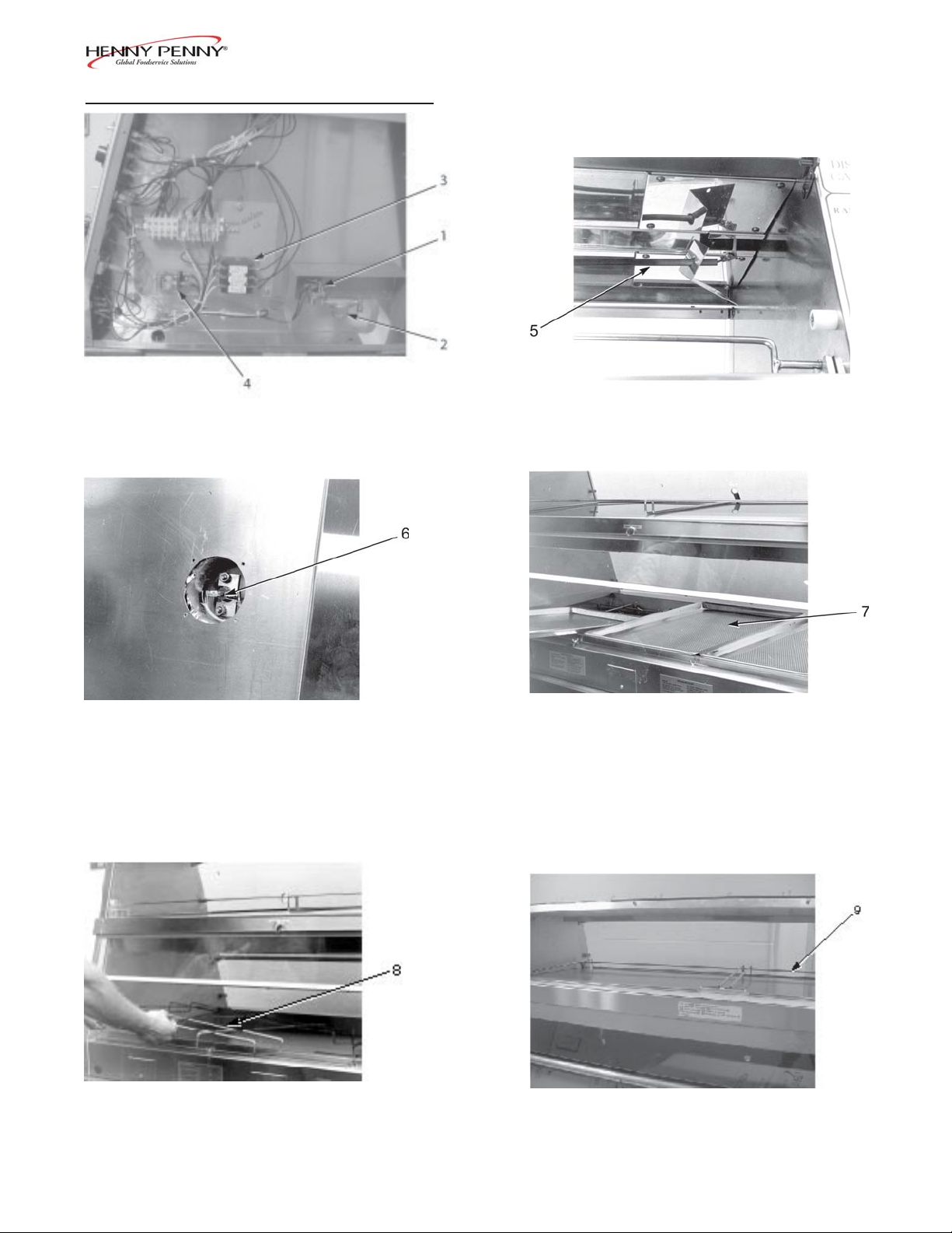
3-1 1 Water Valve An electrical solenoid valve energized by the float
switch or the water control switch (in manual position)
that allows water to flow into the water pan
3-1 2 Water Strainer A filter to prevent particles plugging the water valve
3-1 3 Contactor The relay that directs power to the water heaters
3-1 4 Relay Shuts the heat off to the water pan when a low water
condition is sensed by the float switch
3-2 5 Radiant Heater A long tubular heater mounted in a reflector located in
the ceiling panel of the unit
3-3 6 High Temperature A safety device mounted to the bottom of the water pan
Limit which detects an over temperature condition if the
water pan runs dry
3-4 7 Perforated Used over the water pan to allow the humidity to pass
Bun Pan thru the chicken
3-5 8 Water Pan Grid A grid that sets in the water pan to prevent a bun pan
from dropping into the water when being lifted out
3-6 9 Pan Support - Tilts the bun pans used in the top toward the customer
Top side of the unit
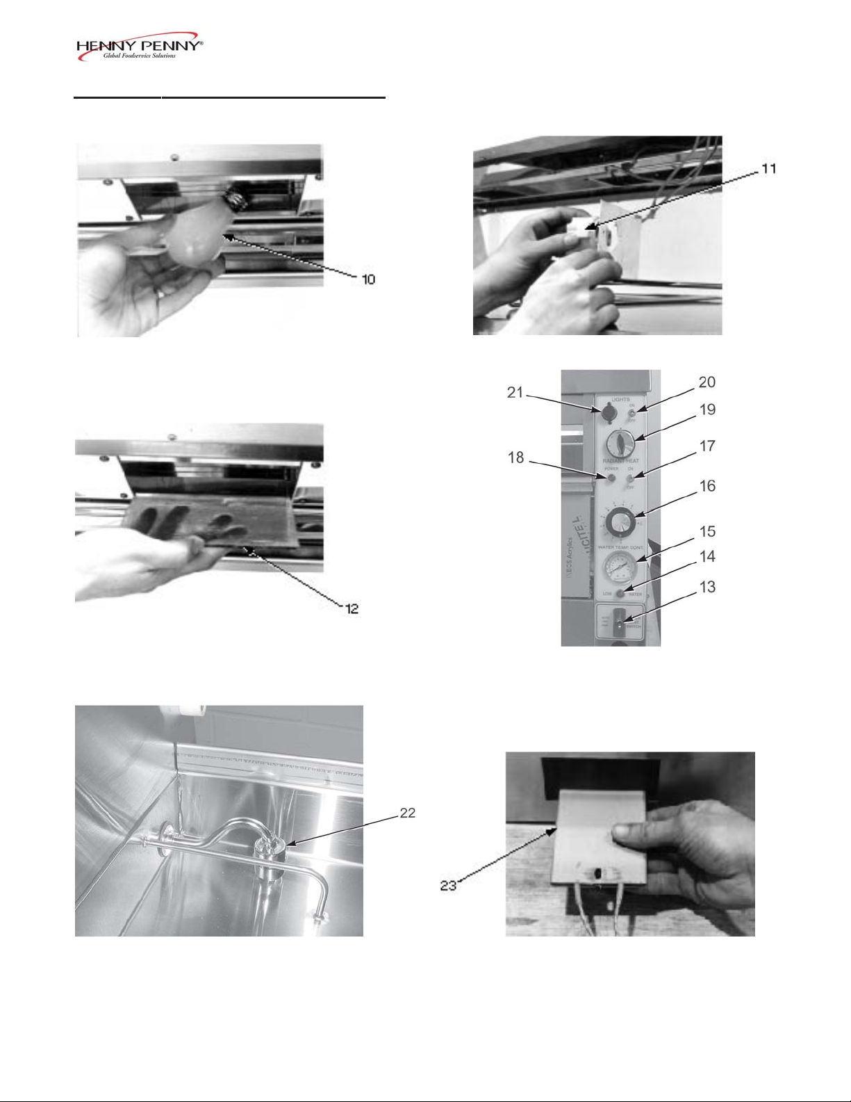
3-7 10 Light Bulb A 60 watt rated, long-life bulb that should be replaced
by the same wattage bulb
3-8 11 Lamp Socket A high temperature ceramic socket for holding the light
bulb
3-9 12 Tinted Glass Specially tempered colored glass with a thin film of
silicone that protects the light bulbs as well as color
the light
3-4 103
Page 5

Model HCS-2/HCW-3/HCW-5/HCW-8
3-2. OPERATING CONTROLS (Continued)
Fig. Item Description Function
No. No.
3-10 13 Water Control A three-position switch with center position being OFF;
Switch in the position marked AUTOMATIC (up), the water
level in the unit will be controlled by the float switch; in
the position marked MANUAL (down), the water
valve is opened directly by the switch; the MANUAL
position is spring loaded so that the water valve will
close when the switch is released
3-10 14 Water Light A light operated directly by the float switch, which when
illuminated, indicates low water conditions no matter
what position the water control switch is in
3-10 15 Thermometer Indicates the water temperature
3-10 16 Water Thermostat An electro-mechanical device used to regulate the
water temperature
3-10 17 Power Switch A two-position, three pole switch used to turn on and
off the heat and water control systems
3-10 18 Power Light A light, when illuminated, indicating when the power
switch is on and the heat and water system controls are
energized; if the power light goes out during normal
operation, this means the water pan high temperature
limit has opened indicating that the unit is out of water
3-10 19 Radiant Heat A time proportioning controller, which means the higher
Infinite Regulator the number setting, the greater percentage of time the
radiant heat will be on
3-10 20 Light Switch A two-position, two pole switch used to turn the lights
ON and OFF
3-10 21 Light Fuse Holder A 15 amp protective device for the lighting circuit, that
must be replaced by a fuse of the same size and rating
103 3-5
Page 6

Model HCS-2/HCW-3/HCW-5/HCW-8
3-2. OPERATING CONTROLS (Continued)
Fig. Item Description Function
No. No.
3-11 22 Float Switch An electro-mechanical sensing device used to automati-
cally control the water level in the water pan; the float
switch can be inactivated by the water control switch;
the float switch illuminates the low water light when it
senses a low water condition
3-12 23 Water Heater Two flat strip heaters, attached to the bottom of the
water pan, which measure approximately 3” wide by
25” long, and are rated at 1020 watts each
3-3. START-UP
Step 2
Before using, the Henny Penny Heated Display Cabinet
should be thoroughly cleaned as indicated in the Shut-Down
and Cleanup section of this manual.
1. Move all switches and controls on the cabinet to the OFF
position.
2. Turn on power supply for the cabinet at the main circuit
breaker.
3. Place the grids in the water pan.
Step 3
3-6 1105
Page 7

3-3. START-UP (Continued)
Model HCS-2/HCW-3/HCW-5/HCW-8
4. Install the perforated bun pans over the water well. This will
help in a more rapid heat up of the water.
5. Close the doors.
6. Turn the power switch to the ON position.
7. Turn the light switch to the ON position.
Step 4
8. Turn the radiant heat switch to the desired setting. We
recommend starting at “6” for the lower radiant. If you have
upper radiant, start at “4”. These settings are adjustable and
may change as you become familiar with the food product
in this unit.
9. Turn the water control switch to AUTOMATIC.
10. After approximately one minute, turn the water thermostat
to the desired setting. We recommend about 3.5 to 4 or a
water temperature of 150°F.
3-4. OPERATION WITH 1. Place product on wire grids in the pans.
PRODUCT
2. Serve product from the outside edges
closest to the door opened often will cool fastest.
3. Only leave the doors open when demand requires. During
slow periods, keep the doors closed.
When checking the HCW to make sure it’s holding the
product properly, use a temperature probe or pocket
thermometer on the product and the water in the bottom of
the unit. The product is kept warm by radiant heat and
checking the air temperature inside the HCW will NOT
indicate if the product is holding at the proper temperature.
Also, even though the unit has a thermometer on the controls for the water temperature, it may not accurate.
first. The product
1105 3-7
Page 8

Model HCS-2/HCW-3/HCW-5/HCW-8
3-5. SHUT-DOWN AND 1. Turn the water thermostat to OFF.
CLEANUP
2. Turn the radiant heat to OFF.
3. Turn the water control switch to OFF.
4. Open the doors.
5. Remove all the pans.
6. Remove the drain standpipe.
7. Remove the grids from the water pan and clean with
soap and water at sink.
8. If cleaning a five-pan unit (HCW-5), or eight-pan unit
Step 6
(HCW-8), remove wire pan support from top section and
clean with soap and water at sink.
Do not use steel wool, other abrasive cleaners or
cleaners/sanitizers containing chlorine, bromine, iodine
or ammonia chemicals, as these will deteriorate the
stainless steel material and shorten the life of the unit.
Do not spray the unit with water, such as, with a garden
hose. Failure to follow this caution could cause component failure.
9. Clean all surfaces with a soft cloth, soap, and water.
10. Clean around electrical controls with a damp cloth.
11. Install the drain standpipe.
12. Turn off the lights and power switch.
13. Leave the doors open until ready to use again.
3-8 1105
 Loading...