


Henny Penny
Humidified Counter Warmer
Model HCW-2
Model HCS-2
Model HCW-3
Model HCW-5
Model HCS-5
Model HCW-8
OPERATOR’S MANUAL

Model HCS-2/HCW-3/HCW-5/HCW-8
LIMITED WARRANTY FOR HENNY PENNY EQUIPMENT
Subject to the following conditions, Henny Penny Corporation makes the following limited warranties to the original
purchaser only for Henny Penny appliances and replacement parts:
NEW EQUIPMENT: Any part of a new appliance, except baskets, lamps, and fuses, which proves to be defective in
material or workmanship within two (2) years from date of original installation, will be repaired or replaced without
charge F .O.B. factory , Eaton, Ohio, or F .O.B. authorized distributor . Baskets will be repaired or replaced for ninety (90)
days from date of original installation. Lamps and fuses are not covered under this Limited W arranty. T o validate this
warranty, the registration card for the appliance must be mailed to Henny Penny within ten (10) days after installation.
FILTER SYSTEM: Failure of any parts within a fryer filter system caused by the use of the non-OEM filters or
other unapproved filters is not covered under this Limited Warranty .
REPLACEMENT PARTS: Any appliance replacement part, except lamps and fuses, which proves to be defective in
material or workmanship within ninety (90) days from date of original installation will be repaired or replaced without
charge F .O.B. factory , Eaton, Ohio, or F .O.B. authorized distributor .
The warranty for new equipment covers the repair or replacement of the defective part and includes labor charges and
maximum mileage charges of 200 miles round trip for a period of one (1) year from the date of original installation.
The warranty for replacement parts covers only the repair or replacement of the defective part and does not include any
labor charges for the removal and installation of any parts, travel, or other expenses incidental to the repair or replacement of
a part.
EXTENDED FRYPOT WARRANTY: Henny Penny will replace any frypot that fails due to manufacturing or workmanship
issues for a period of up to seven (7) years from date of manufacture. This warranty shall not cover any frypot that fails due to
any misuse or abuse, such as heating of the frypot without shortening.
0 TO 3 YEARS: During this time, any frypot that fails due to manufacturing or workmanship issues will
be replaced at no charge for parts, labor, or freight. Henny Penny will either install a new frypot at no cost or
provide a new or reconditioned replacement fryer at no cost.
3 TO 7 YEARS: During this time, any frypot that fails due to manufacturing or workmanship issues will
be replaced at no charge for the frypot only . Any freight charges and labor costs to install the new frypot as
well as the cost of any other parts replaced, such as insulation, thermal sensors, high limits, fittings, and
hardware, will be the responsibility of the owner.
Any claim must be presented to either Henny Penny or the distributor from whom the appliance was purchased. No
allowance will be granted for repairs made by anyone else without Henny Penny’s written consent. If damage occurs during
shipping, notify the sender at once so that a claim may be filed.
THE ABOVE LIMITED WARRANTY SETS FOR TH THE SOLE REMEDY AGAINST HENNY PENNY FOR ANY BREACH
OF W ARRANTY OR OTHER TERM. BUYER AGREES THA T NO OTHER REMEDY (INCLUDING CLAIMS FOR ANY INCIDENT AL OR CONSEQUENTIAL DAMAGES) SHALL BE AV AILABLE.
The above limited warranty does not apply (a) to damage resulting from accident, alteration, misuse, or abuse; (b) if the
equipment’s serial number is removed or defaced; or (c) for lamps and fuses. THE ABOVE LIMITED WARRANTY IS EXPRESSL Y IN LIEU OF ALL OTHER W ARRANTIES, EXPRESS OR IMPLIED, INCLUDING MERCHANT ABILITY AND FITNESS, AND ALL OTHER W ARRANTIES ARE EXCLUDED. HENNY PENNY NEITHER ASSUMES NOR AUTHORIZES ANY
PERSON TO ASSUME FOR IT ANY OTHER OBLIGA TION OR LIABILITY.
Revised 01/01/07
FM05-019-F
Revised 02-14-07

Model HCS-2/HCW-3/HCW-5/HCW-8
TABLE OF CONTENTS
Section Page
Section 1. INTRODUCTION ....................................................................................................... 1-1
1-1. Heated Display Cabinet ....................................................................................... 1-1
1-2. Features .............................................................................................................. 1-1
1-3. Proper Care........................................................................................................ 1-1
1-4. Assistance ........................................................................................................... 1-1
1-5. Safety ................................................................................................................. 1-2
Section 2. INST ALLATION ......................................................................................................... 2-1
2-1. Introduction......................................................................................................... 2-1
2-2. Unpacking........................................................................................................... 2-1
2-3. Location.............................................................................................................. 2-3
2-4. Remove Control End Panel.................................................................................. 2-3
2-5. Drain Connection ................................................................................................ 2-4
2-6. Electric Connection ............................................................................................. 2-4
2-7. Electric Data T able .............................................................................................. 2-5
2-8. Water Supply Connection .................................................................................... 2-5
2-9. Light Bulbs and Glass Panels ............................................................................... 2-6
2-10. Cabinet Dimensions ............................................................................................. 2-7
Section 3. OPERA TION............................................................................................................... 3-1
3-1. Introduction......................................................................................................... 3-1
3-2. Operating Controls .............................................................................................. 3-1
3-3. Start-Up ............................................................................................................. 3-6
3-4. Operation with Product ....................................................................................... 3-7
3-5. Shut-Down and Cleanup ..................................................................................... 3-8
Section 4. TROUBLESHOOTING ............................................................................................... 4-1
4-1. Troubleshooting Guide ......................................................................................... 4-1
GLOSSARY............................................................................................................................ G-1
Distributor Lists - Domestic and International
i 1105
Model HCS-2/HCW-3/HCW-5/HCW-8
SECTION 1. INTRODUCTION
1-1. HEA TED DISPLA Y The Henny Penny Heated Display Cabinet is a basic unit of food
CABINET processing equipment used to display the food product and
maintain the temperature of hot foods in the commercial food
service operation. This highly efficient, quality-built cabinet will keep
hot foods at proper holding temperatures with controlled humidity .
The Henny Penny Heated Display Cabinets have see-thru doors
which allow viewing and access to the hot foods from both front
and back.
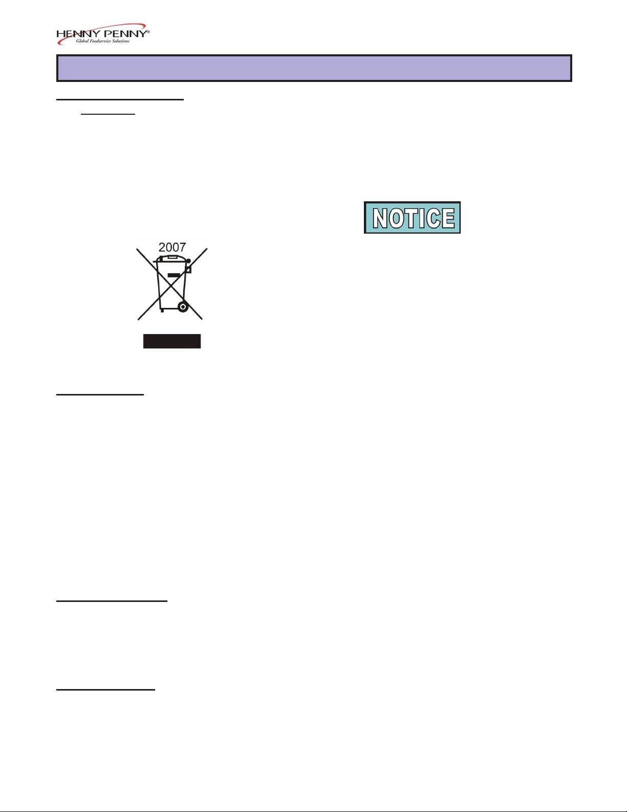
As of August 16, 2005, the W aste Electrical and Electronic Equipment directive went into effect for the European Union. Our
products have been evaluated to the WEEE directive. W e have
also reviewed our products to determine if they comply with the
Restriction of Hazardous Substances directive (RoHS) and have
redesigned our products as needed in order to comply . T o continue
compliance with these directives, this unit must not be disposed as
unsorted municipal waste. For proper disposal, please contact
your nearest Henny Penny distributor .
1-2. FEA TURES • Moist heat (HCS-2, HCW -3, and lower section HCW-5 and
HCW-8)
• Dry heat in top section (HCW -5 and HCW-8 only)
• Easy to keep clean
• Automatic water fill system with manual bypass
• HCW -3 and the lower section HCW-5 holds three trays of
product
• Lower section HCW -8 holds five trays
• T op section HCW -5 holds two trays of product
• T op section HCW -8 holds three trays
• All heat sources are adjustable
• Flip-up, see-through door panels
1-3. PROPER CARE As in any unit of food service equipment, the Henny Penny Heated
Display Cabinet does require care and maintenance. Requirements
for the maintenance and cleaning are contained in this manual and
must become a regular part of the operation of the unit at all times.
1-4. ASSISTANCE Should you require outside assistance, just call your local
independent Henny Penny distributor in your area, call Henny
Penny Corp. at 1-800-417-8405 toll free or 1-937-456-8405, or
go to Henny Penny online at www .hennypenny.com.
207 1-1
Model HCS-2/HCW-3/HCW-5/HCW-8
1-5. SAFETY The only way to ensure safe operation of the Henny Penny Heated
Display Cabinet is to fully understand the proper installation,
operation, and maintenance procedures. The instructions in this
manual have been prepared to aid you in learning the proper
procedures. Where information is of particular importance or is
safety related, the words NOTICE, CAUTION, or W ARNING
are used. Their usage is described below .
SAFETY ALER T SYMBOL is used with DANGER,
W ARNING, or CAUTION which indicates a personal injury
type hazard.
NOTICE is used to highlight especially important information.
CAUTION used without the safety alert symbol indicates
a potentially hazardous situation which, if not avoided, may
result in pr operty damage.
CAUTION indicates a potentially hazardous situation
which, if not avoided, may result in minor or moderate
injury.
The word WARNING is used to alert you to a procedure,
that if not performed properly , might cause personal
injury.
1-2 103
Model HCS-2/HCW-3/HCW-5/HCW-8
SECTION 2. INSTALLATION
2-1. INTRODUCTION This section provides the installation instructions for the Henny
Penny Heated Display Cabinet.
Installation of this unit should be performed only by a qualified
service technician.
Do not puncture the skin of the unit with drills or
screws as component damage or electrical shock
could result.
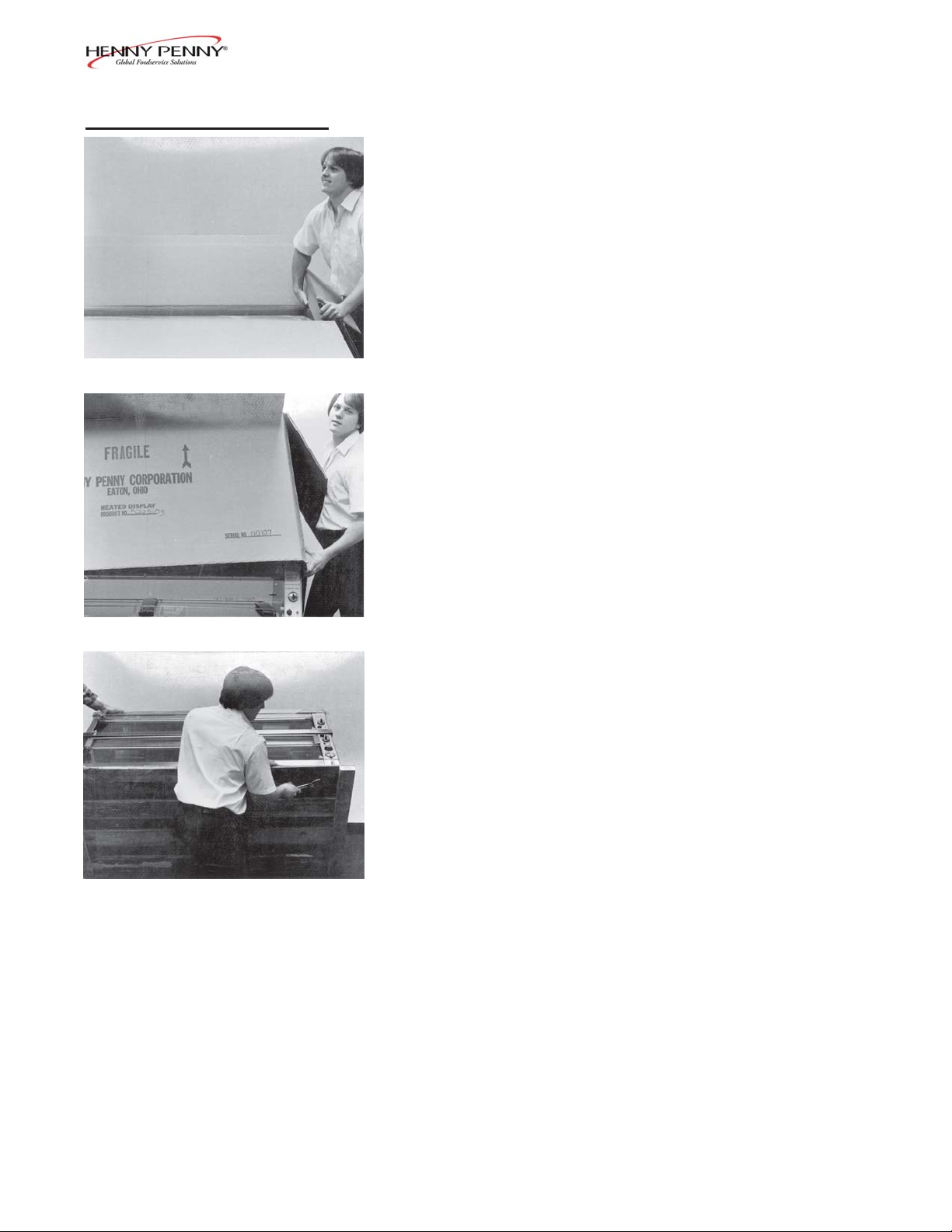
2-2. UNP ACKING The Henny Penny Heated Display Cabinet has been tested,
inspected, and expertly packed to ensure arrival at its destination in
the best possible condition. The cabinet has been bolted to a
wooden skid. All glass items have been packed in cartons and
taped inside the unit and the doors taped shut. The unit is then
packed inside a triple wall corrugated carton with sufficient padding
to withstand normal shipping treatment.
Any shipping damages should be noted in the presence of the
delivery agent and signed prior to his or her departure.
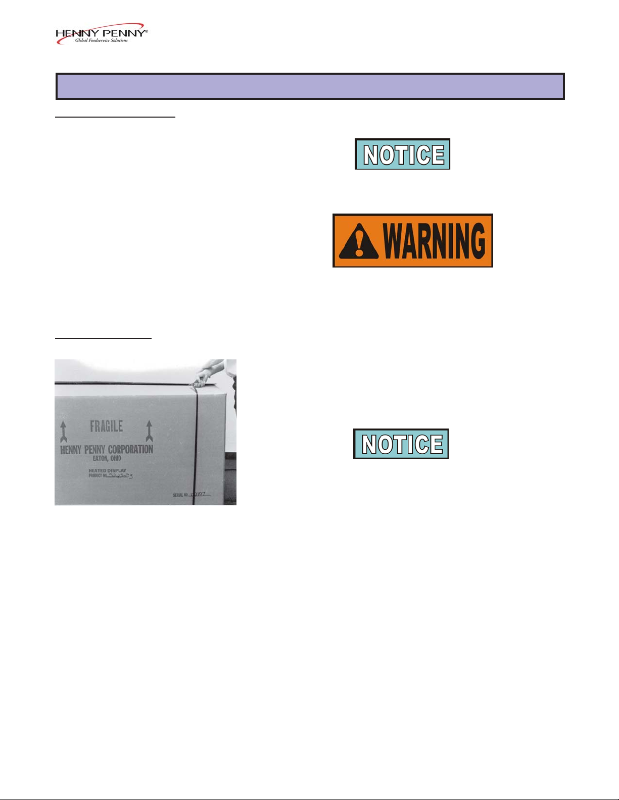
Step 1
T o remove the Henny Penny Heated Display Cabinet from the
carton, you should:
1. Carefully cut banding straps.
203 2-1
2-2. UNP ACKING (Continued)
Model HCS-2/HCW-3/HCW-5/HCW-8
2. Open top flaps and remove packing.
Step 2
3. Lift carton off skid.
Step 3
Step 4
4. Remove four bolts from under skid.
The unit is now ready for location and set-up.
2-2 103

Model HCS-2/HCW-3/HCW-5/HCW-8
2-3. LOCA TION Place the unit on a table, preferably with a cut-out opening below
the cabinet to allow easy service connections and serviceability .
When setting up the Henny Penny Heated Display Cabinet, be sure
to level the table.
The unit has built-in draining capabilities, but this becomes
ineffective when set on an unlevel table.
After the Henny Penny Heated Display Cabinet has been leveled
on the table, run a bead of silicone rubber (silicone or equivalent
sealant must be a NSF listed material) around the perimeter of the
unit sealing it to the table top. You are now ready to make the
electrical and drain connections to the unit.
2-4. REMOVE CONTROL END 1. Remove the seven screws fastening the end panel to the cabinet.
PANEL
Step 2
2. Slide bottom of end panel out first allowing top to drop below
shelf edge.
103 2-3

Model HCS-2/HCW-3/HCW-5/HCW-8
2-5. DRAIN CONNECTION The drain can be connected to a 1 inch N.P .T . directly below the
water well or to a 3/4 inch N.P .T . from the operator’ s side. W e
recommend the 1 inch N.P .T . connection as this will allow straight
down draining of the water.
2-6. ELECTRIC CONNECTION The heated display cabinet is available from the factory wired for
208 or 230 volts, single phase, 3-wire (includes neutral) or three
phase, 4-wire (includes neutral) 50 or 60 Hz. service. The proper power
service cable must be provided at installation. Check the data plate
on the side panel of the control end to determine the correct power
supply .
T o avoid electrical shock, the cabinet must be
adequately and safely grounded (earthed) according to
local electrical codes.
(FOR EQUIPMENT WITH CE MARK ONL Y!)
T o prevent electric shock hazard this appliance must be
bonded to other appliances or touchable metal surfaces
in close proximity to this appliance with an
equipotential bonding conductor . This appliance is
equipped with an equipotential lug for this purpose.
The equipotential lug is marked with the following
symbol
A separate disconnect switch with proper capacity fuses or
breakers must be installed at a convenient location between the
cabinet and the power source. The field supply wiring to the cabinet
should be an insulated copper conductor rated for 600 volts and
90°C.
2-4 1004

Model HCS-2/HCW-3/HCW-5/HCW-8
2-6. ELECTRICAL CONNECTION The electrical power can be connected from the bottom or from the
(Continued) operator’s side. There is a 1-3/32 inch diameter hole for either
connection. Again, we recommend the bottom connection as this
will give a cleaner appearance to the unit. Please observe the
electrical connection information on the data plate located on the
side panel of the control end.
Voltage potential of L1 and L2 to ground cannot exceed
125 volts, or damage to the unit could result.
2-7. ELECTRIC DA TA TABLE Model Volts Phase Watts Amps
HCW-2 120/230 1 760 4.7
HCW-2 120/208 1 760 4.9
HCS-2 230 1 2852 12.4
HCW-3 120/230 3 3400 10.7
HCW-3 120/230 1 3400 16.3
HCW-3 120/208 3 3400 11.5
HCW-3 120/208 1 3400 17.6
HCW-3 400 3 3400 5.0
HCW-5 120/230 3 4160 12.2
HCW-5 120/230 1 4160 18.0
HCW-5 120/208 3 4160 13.1
HCW-5 120/208 1 4160 19.5
HCW-5 400 3 4160 6.0
HCW-8 120/208 3 8080 26.0
HCW-8 120/208 1 8080 40.0
HCW-8 120/230 3 8080 24.0
HCW-8 120/230 1 8080 35.1
HCW-8 400 3 8080 11.7
HCS-5 120/208 3 8080 22.6
HCS-5 120/208 1 8080 40.0
HCS-5 120/230 3 8080 19.8
HCS-5 120/230 1 8080 35.1
HCS-5 400 3 6680 9.7
2-8. WATER SUPPL Y The automatic water system has a 1/4 inch compression fitting for
CONNECTION copper tubing. Hot water would be preferred. W e recommend
using the automatic water system as this will allow the unit to
maintain a more even water temperature and help ensure that the
unit never runs dry of water.
A straight-through bulkhead fitting is furnished with the unit for
1/4 inch copper tubing to protect the water line where it passes
through the sheet metal.
Reinstall the end panel.
1006 2-5

Model HCS-2/HCW-3/HCW-5/HCW-8
2-8. WATER SUPPL Y
CONNECTION
(Continued) This unit as manufactured requires the installation of an
appropriate back-siphoning device (as per National Plumbing
Code ASA-A40.8-1955) to be connected to the water inlet
line. This device to be connected in accordance to the basic
plumbing code of the Building Officials and Code
Administrators International, Inc. (BOCA), and the Food
Service Sanitation Manual of the Food and Drug Administration
(FDA).
A water shut-off valve should be installed in a convenient
location.
2-9. LIGHT BULBS AND
GLASS P ANELS 1. Cut the tape holding the doors shut and remove all boxes and
boxes and packing. One carton contains the glass panels and
the other contains the light bulbs.
Step 1
2. Install the light bulbs and glass panels.
3. The unit is now ready to be cleaned per instructions in the
Operations section of this manual.
Replacing Light Bulbs
Light bulbs and glass may be hot. Severe burns could result.
1. Remove the glass panel by carefully pushing up on back of
panel and sliding away from you. The panel will fall into
your hand. See photo at left.
2. Remove the light bulb.
3. Replace the light bulb with a W estinghouse #60A19/35,
130 V olt bulb.
If this bulb is not available, a standard 60 watt bulb will work
Step 2
until a long life bulb can be obtained.
4. Replace the glass panel.
2-6 103

2-10. CABINET DIMENSIONS
Model HCS-2/HCW-3/HCW-5/HCW-8
Model HCS-2
Model HCW-3
1006 2-7

2-10. CABINET DIMENSIONS
(Continued)
Model HCS-2/HCW-3/HCW-5/HCW-8
Model HCW-5
2-8 1006

Model HCS-2/HCW-3/HCW-5/HCW-8
SECTION 3. OPERATING INSTRUCTIONS
3-1. INTRODUCTION This section provides operating procedures for the heated display
cabinets. The Introduction, Installation and Operation sections
should be read, and all instructions should be followed before
operating the cabinet.
3-2. OPERA TING CONTROLS Figures 3-1 through 3-12 identify and describe the function of all the
operating controls and the major components of the cabinet.
103 3-1

3-2. OPERA TING CONTROLS (Continued)
Model HCS-2/HCW-3/HCW-5/HCW-8
Figure 3-1
Figure 3-3 Figure 3-4
Figure 3-2
Figure 3-5 Figure 3-6
3-2 103

3-2. OPERA TING CONTROLS (Continued)
Figure 3-7
Model HCS-2/HCW-3/HCW-5/HCW-8
Figure 3-8
Figure 3-9
Figure 3-11
103 3-3
Figure 3-10
Figure 3-12

Model HCS-2/HCW-3/HCW-5/HCW-8
3-2. OPERA TING CONTROLS (Continued)
Fig. Item Description Function
No. No.
3-1 1 Water Valve An electrical solenoid valve energized by the float
switch or the water control switch (in manual position)
that allows water to flow into the water pan
3-1 2 Water Strainer A filter to prevent particles plugging the water valve
3-1 3 Contactor The relay that directs power to the water heaters
3-1 4 Relay Shuts the heat off to the water pan when a low water
condition is sensed by the float switch
3-2 5 Radiant Heater A long tubular heater mounted in a reflector located in
the ceiling panel of the unit
3- 3 6 High Temperature A safety device mounted to the bottom of the water pan
Limit which detects an over temperature condition if the
water pan runs dry
3-4 7 Perforated Used over the water pan to allow the humidity to pass
Bun Pan thru the chicken
3-5 8 W ater Pan Grid A grid that sets in the water pan to prevent a bun pan
from dropping into the water when being lifted out
3-6 9 Pan Support - Tilts the bun pans used in the top toward the customer
T op side of the unit
3- 7 10 Light Bulb A 6 0 watt rated, long-life bulb that should be replaced
by the same wattage bulb
3-8 11 Lamp Socket A high temperature ceramic socket for holding the light
bulb
3- 9 12 Tinted Glass Specially tempered colored glass with a thin film of
silicone that protects the light bulbs as well as color
the light
3-4 103

Model HCS-2/HCW-3/HCW-5/HCW-8
3-2. OPERA TING CONTROLS (Continued)
Fig. Item Description Function
No. No.
3-10 13 Water Control A three-position switch with center position being OFF;
Switch in the position marked AUTOMA TIC (up), the water
level in the unit will be controlled by the float switch; in
the position marked MANUAL (down), the water
valve is opened directly by the switch; the MANUAL
position is spring loaded so that the water valve will
close when the switch is released
3-10 14 Water Light A light operated directly by the float switch, which when
illuminated, indicates low water conditions no matter
what position the water control switch is in
3-10 15 Thermometer Indicates the water temperature
3-10 16 Water Thermostat An electro-mechanical device used to regulate the
water temperature
3-10 17 Power Switch A two-position, three pole switch used to turn on and
off the heat and water control systems
3-10 18 Power Light A light, when illuminated, indicating when the power
switch is on and the heat and water system controls are
energized; if the power light goes out during normal
operation, this means the water pan high temperature
limit has opened indicating that the unit is out of water
3-10 19 Radiant Heat A time proportioning controller, which means the higher
Infinite Regulator the number setting, the greater percentage of time the
radiant heat will be on
3-10 20 Light Switch A two-position, two pole switch used to turn the lights
ON and OFF
3-10 21 Light Fuse Holder A 15 amp protective device for the lighting circuit, that
must be replaced by a fuse of the same size and rating
103 3-5

Model HCS-2/HCW-3/HCW-5/HCW-8
3-2. OPERA TING CONTROLS (Continued)
Fig. Item Description Function
No. No.
3-11 22 Float Switch An electro-mechanical sensing device used to automati-
cally control the water level in the water pan; the float
switch can be inactivated by the water control switch;
the float switch illuminates the low water light when it
senses a low water condition
3-12 23 Water Heater T wo flat strip heaters, attached to the bottom of the
water pan, which measure approximately 3” wide by
25” long, and are rated at 1020 watts each
3-3. ST ART-UP
Step 2
Before using, the Henny Penny Heated Display Cabinet
should be thoroughly cleaned as indicated in the Shut-Down
and Cleanup section of this manual.
1. Move all switches and controls on the cabinet to the OFF
position.
2. Turn on power supply for the cabinet at the main circuit
breaker.
3. Place the grids in the water pan.
Step 3
3-6 1105

3-3. ST ART-UP (Continued)
Model HCS-2/HCW-3/HCW-5/HCW-8
4. Install the perforated bun pans over the water well. This will
help in a more rapid heat up of the water.
5. Close the doors.
6. Turn the power switch to the ON position.
7. Turn the light switch to the ON position.
Step 4
8. Turn the radiant heat switch to the desired setting. We
recommend starting at “6” for the lower radiant. If you have
upper radiant, start at “4”. These settings are adjustable and
may change as you become familiar with the food product
in this unit.
9. Turn the water control switch to AUTOMATIC.
10. After approximately one minute, turn the water thermostat
to the desired setting. W e recommend about 3.5 to 4 or a
water temperature of 150°F .
3-4. OPERA TION WITH 1. Place product on wire grids in the pans.
PRODUCT
2. Serve product from the outside edges first. The product
closest to the door opened often will cool fastest.
3. Only leave the doors open when demand requires. During
slow periods, keep the doors closed.
When checking the HCW to make sure it’ s holding the
product properly , use a temperature probe or pocket
thermometer on the product and the water in the bottom of
the unit. The product is kept warm by radiant heat and
checking the air temperature inside the HCW will NOT
indicate if the product is holding at the proper temperature.
Also, even though the unit has a thermometer on the controls for the water temperature, it may not accurate.
1105 3-7

Model HCS-2/HCW-3/HCW-5/HCW-8
3-5. SHUT -DOWN AND 1. Turn the water thermostat to OFF .
CLEANUP
2. Turn the radiant heat to OFF.
3. Turn the water control switch to OFF.
4. Open the doors.
5. Remove all the pans.
6. Remove the drain standpipe.
7. Remove the grids from the water pan and clean with
soap and water at sink.
8. If cleaning a five-pan unit (HCW -5), or eight-pan unit
Step 6
(HCW-8), remove wire pan support from top section and
clean with soap and water at sink.
Do not use steel wool, other abrasive cleaners or
cleaners/sanitizers containing chlorine, bromine, iodine
or ammonia chemicals, as these will deteriorate the
stainless steel material and shorten the life of the unit.
Do not spray the unit with water, such as, with a garden
hose. Failure to follow this caution could cause component failure.
9. Clean all surfaces with a soft cloth, soap, and water .
10. Clean around electrical controls with a damp cloth.
11. Install the drain standpipe.
12. Turn of f the lights and power switch.
13. Leave the doors open until ready to use again.
3-8 1105

Model HCS-2/HCW-3/HCW-5/HCW-8
SECTION 4. TROUBLESHOOTING
4-1. TROUBLESHOOTING GUIDE
PROBLEM CAUSE CORRECTION
Product not
• Doors are not kept closed • Keep doors closed when
holding possible
temperature
• Product held too long • Only hold product for
recommended times
• Water temperature too low • Turn to higher setting
• Radiant heat too low • Turn to higher setting
• Light bulbs out • Replace as required, per
Light Bulbs and Glass Panels
section
Doors are • Doors left open too much • Keep doors closed when
fogging allowing doors to cool and possible
cause condensation
• Radiant heat not high enough • Turn to higher setting
• Water temperature too high • See recommended settings
and temperatures
W ater will • W ater supply has been shut- • Check the water supply
not fill off or disconnected
Lights will • Defective fuse • Replace 15 amp fuse
not turn on
Not all lights • Faulty light bulbs • Replace with recommended
on bulb, per Light Bulbs and Glass
Panels section
W ater will not • Bun pans are not over water • Place perforated bun pans
reach desired over water
temperature
More detailed troubleshooting information is available in the T echnical Manual, available at www .hennypenny .com,
or 800-417-8405 or 937-456-8405.
203 4-1

Model HCS-2/HCW-3/HCW-5/HCW-8
G L O S S A R Y
HENNY PENNY HOLDING CABINETS
air temperature probe a round device located inside the cabinet that measures the inside air
temperature and sends that information to the control panel
concentration ring assembly a metal assembly located in the water pan in the bottom of the unit that
helps keep an even humidity level inside the cabinet
clean water pan setpoint a preset temperature at which a sensor warns the operator that the water pan
has excessive lime deposits
control panel the components that control the operating systems of the unit; the panel is
located on the top front surface of the cabinet
deliming agent a cleaner used to remove lime deposits in the water pan
drain valve a device that lets the water drain from the water pan into a shallow pan on
the floor; the valve should be closed while the unit is in use if humidity is
desired
float switch a device that senses low water levels in the water pan
food probe a sensor located outside the cabinet that, when inserted into the product,
communicates the temperature of the product to the control panel
food probe receptacle the connection where the food probe is inserted in order to communicate
with the control panel
humidity sensor a device that measures the percentage of humidity inside the cabinet during
use
humidity setting a preset moisture level at which the cabinet operates; this setting is
programmed at the factory but can be changed in the field
LED an electronic light on the control panel
minimum holding temperature the lowest temperature at which a food product can be safely held for
human consumption
module the removable top part of the cabinet that contains all of the operating
system
out of water trip point a preset temperature at which a sensor warns the operator that the water
pan needs refilled
parameters a preset group of setpoints designed for holding specific food products at
certain temperature and humidity levels
power switch the ON/OFF switch that sends electricity to the unit’s operating systems;
this switch does not disconnect the electrical power from the wall to the unit
pressure sprayer a device that shoots a stream of water under pressure; this device should
NOT be used to clean a holding cabinet
G-1 103

Model HCS-2/HCW-3/HCW-5/HCW-8
probe clip a metal holder that attaches to the outside of the control panel to hold the
food probe when not in use; the clip is an optional accessory
product load capacity the highest recommended number of pounds/kilograms of food product that
can be safely held in the cabinet
proof function a program used for allowing bread to rise
relative humidity the humidity level outside the cabinet
setpoint a preset temperature or humidity; the setpoint is a programmable feature
system initialization a programming process that resets factory settings
temperature setting a preset temperature up to which the cabinet will heat; this setting is
programmed at the factory but can be changed in the field
vent activation switch an automatic control that opens and closes the vent on the rear of the
cabinet to maintain the preset humidity level
vented panels openings on the cabinet that allow air access on the sides and rear of the
module
water fill line the line marked on the inside of the water pan that shows the maximum
water level to prevent overflow onto the floor
water heater sensor a part in the water heater that sends a message to the controls when the
water pan is limed up or empty
water jet a device that shoots a stream of water under pressure; this type of device
should NOT be used to clean a holding cabinet
water pan the area in the cabinet that holds water for creating humidity inside the
cabinet
103 G-2

*FM0
5-0
19
-F*
Henny Penny Corp., Eaton, Ohio 45320, Revised 02-14-07
Henny Penny Corporation
P.O.Box 60
Eaton,OH 45320
1-937-456-8400
1-937-456-8402 Fax
Toll free in USA
1-800-417-8417
1-800-417-8434 Fax
www.hennypenny.com
 Loading...