

Page 1

HENNY PENNY
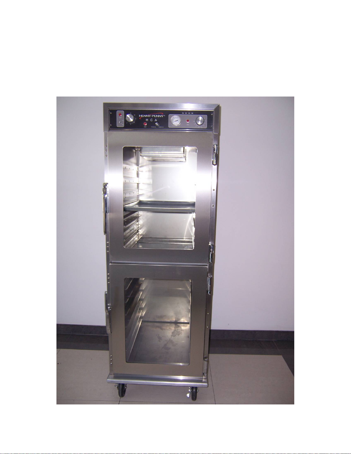
Humidity Control Adjustable
Model HCA910/905
2011/12/09
FM05-058-B
12/09/11
Page 2
HENNY PENNY
Humidity Control Adjustable
Model HCA910
Page 3
LIMITED WARRANTY FOR HENNY PENNY EQUIPMENT
Subject to the following conditions, Henny Penny Corporation makes the following limited warranties
to the original purchaser only for Henny Penny appliances and replacement parts:
NEW EQUIPMENT:
proves to be defective in material or workmanship within one (1) year from date of original
installation, will be repaired or replaced without charge F.O.B. factory, Eaton, Ohio, or F.O.B.
authorized distributor. Baskets will be repaired or replaced for ninety (90) days from date of
original installation. Lamps and fuses are not covered under this Limited Warranty. To validate
this warranty, the registration card for the appliance must be mailed to Henny Penny within ten (10)
days after installation.
FILTER SYSTEM
non-OEM filters or other unapproved filters is not
REPLACEMENT PARTS:
proves to be defective in material or workmanship within ninety (90) days from date of original
installation will be repaired or replaced without charge F.O.B. factory, Eaton, Ohio, or F.O.B.
authorized distributor.
The warranty for new equipment covers the repair or replacement of the defective part and includes
labor charges and maximum mileage charges of 200 miles round trip for a period of one (90) days from the
date of original installation.
The warranty for replacement parts covers only the repair or replacement of the defective part and does
not include any labor charges for the removal and installation of any parts, travel, or other expenses
incidental to the repair or replacement of a part.
Any claim must be presented to either Henny Penny or the distributor from whom the appliance was
purchased. No allowance will be granted for repairs made by anyone else without Henny Penny’s written
consent. If damage occurs during shipping, notify the sender at once so that a claim may be filed.
THE ABOVE LIMITED WARRANTY SETS FORTH THE SOLE REMEDY AGAINST HENNY
PENNY FOR ANY BREACH OF WARRANTY OR OTHER TERM. BUYER AGREES THAT NO
OTHER REMEDY (INCLUDING CLAIMS FOR ANY INCIDENTAL OR CONSEQUENTIAL
DAMAGES) SHALL BE AVAILABLE.
The above limited warranty does not apply (a) to damage resulting from accident, alteration, misuse, or
abuse; (b) if the equipment’s serial number is removed or defaced; or (c) for lamps and fuses. THE
ABOVE LIMITED WARRANTY IS EXPRESSLY IN LIEU OF ALL OTHER WARRANTIES,
EXPRESS OR IMPLIED, INCLUDING MERCHANTABILITY AND FITNESS, AND ALL OTHER
WARRANTIES ARE EXCLUDED. HENNY PENNY NEITHER ASSUMES NOR AUTHORIZES
ANY PERSON TO ASSUME FOR IT ANY OTHER OBLIGATION OR LIAB ILITY.
Any part of a new appliance, except baskets, lamps, and fuses, which
: Failure of an y parts within a fryer filter system caused by the use of the
covered under this Limited Warranty.
Any appliance replacement part, except lamps and fuses, which
Revised 5/13/10
Page 4

TABLE OF CONTENTS
Section Page
Section 1. INTRODUCTION………………………………………………………..1-1
1-1. Heated Holding Cabinet...........................................................1-1
1-2. Features...................................................................................1-1
1-3. Proper Care.............................................................................1-1
1-4. Assistance................................................................................1-1
1-5. Safety.......................................................................................1-2
Section 2. INSTALLATION................................................................................2-1
2-1. Introduction..............................................................................2-1
2-2. Unpacking................................................................................2-1
2-3. Location....................................................................................2-2
2-4. Electrical Connection................................................................2-2
2-5. Cabinet Dimensions..................................................................2-3
2-6. Water Supply Connection..........................................................2-4
2-7. Wire diagram……………………………………………………….2-5
Section 3. OPERATION......................................................................................3-1
3-1. Introduction................................................................................3-1
3-2. Operating Controls and Components........................................3-1
3-3. Start-Up.....................................................................................3-6
3-4. Operation with product..............................................................3-7
3-5. Cleaning Procedures.................................................................3-7
Page 5
1-1. HUMIDITY CONTROL
ADJUSTABLE (HCA910/905)
1-2. FEATURES
1-3. PROPER CARE
1-4. ASSISTANCE
The Henny Penny humidity control adjustable is a basic
unit of food processing equipment designed to hold hot
foods at proper temperature in commercial food operations.
This cabinet will keep hot foods humid while maintaining
temperature.
•Easily cleaned
•Automatic water fill
•Adjustable, thermostatically controlled heat
•Lift-off doors
•Easy access to electrical components
•Moist heat
•Removable control module
•Stainless steel construction
•Full perimeter magnetic door seals
•Lift out tray racks
•UL & NSF listed
•Adjustable humidity
As in any unit of food service equipment, the Henny
Penny heated holding cabinet does require care and
maintenance. Requirements for the maintenance and
cleaning are contained in this manual and must
become a regular part of the operation of the unit at
all times.
Should you require outside assistance, just call your
local independent Henny Penny distributor in your
area, or call Henny Penny Corp.1-800-417-8405 toll
free or 1-937-456-8405.
1-1
Page 6

1-5. SAFETY
The only way to insure safe operation of the Henny Penny
heated holding cabinet is to fully understand the proper
installation, operation, and maintenance procedures. The
instructions in this manual have been prepared to aid you in
learning the proper procedures. Where information is of
particular importance or is safety related, the words
NOTICE, CAUTION, or WARNING are used . Their usage
is described below.
SAFETYALERT SYMBOL is used with DANGER,
WARNING, or CAUTION which indicates a personal
injury type hazard.
NOTICE is used to highlight especially important
information.
CAUTION used without the safety alert
symbol indicates a potentially hazardous
situation which, if not avoided, may result in
property damage.
CAUTION indicates a potentially hazardous
situation which, if not avoided, may result in
minor or moderate injury.
The word WARNING is used to alert you to
a procedure, that if not performed properly,
might cause personal injury.
1-2
Page 7

2-1. INTRODUCTION
2-2. UNPACKING
This section provides the installation instructions for the
Henny Penny Humidity Control Adjustable.
Installation of this unit should be performed only by
a qualified service technician.
Do not puncture the skin of the unit with drills or
screws as component damage or electrical shock
could result.
The Henny Penny humidity control adjustable has
been tested, inspected, and expertly packed to
ensure arrival at its destination in the best possible
condition. The cabinet rests on cardboard pads that
sit on a wooden skid. The racks inside the cabinet
are secured with cardboard packing. The unit is then
packed inside a heavy cardboard carton with
sufficient padding to withstand normal shipping
treatment.
Any shipping damage should be noted in the
presence of the delivery agent and signed prior to
his or her departure.
To remove the Henny Penny heated holding cabinet
from the carton, you should:
1. Carefully cut banding straps.
2. Lift the carton off the unit.
2-1
Page 8

2-3. LOCATION
2-4. ELECTRICAL
CONNECTION
3. Lift the unit off the cardboard padding and skid.
Take care when moving the fryer to prevent
personal injury. The unit weighs 379 lbs. (172 kg.).
4. Open doors and remove packing from behind
racks.
5. Peel off any protective covering from the exterior
of the cabinet.
6. The unit is now ready for location and set up.
The HCA910/905 should be placed in an area where
the doors can be opened without interruption and
loading and unloading of product is easy. For proper
operation, the cabinet must be level.
To prevent damaging the unit, do not set anything
on top of the cabinet that might close off the vent
holes.
The heated holding cabinet is available from the
factory as a 240 VAC unit. The data plate, located
on the side of the module, will specify the correct
electrical supply. The unit requires a grounded
receptacle with a separate electrical line protected
by a fuse or circuit breaker of the proper rating.
This unit must be adequately and safely grounded.
Refer to local electrical codes for correct
grounding procedures. If unit is not adequately
grounded, electrical shock could result.
2-2
Page 9

2-5. CABINET DIMENSIONS
Model Number Volts(V) Watts (W) Amps (A) Cycle(HZ)
HCA910/905 240 2524 10.8 50/60
2-3
Page 10

2-6. WATER SUPPLY
CONNECTION
The automatic water fill system requires a water
supply. The unit is equipped with a water strainer
and clamp for a hose connection. It is also equipped
with an eight foot nylabraid hose tubing. Run the
tubing to the cabinet location, providing enough
tubing to allow movement of the unit for cleaning or
maintenance. The use of a water condition or filter
is recommended. A shut-on valve should be
installed in the supply line.
Do not operate this unit without water connected to
cabinet, or damage to components will result.
To install water supply connection, follow these
steps:
1. Flush the incoming water line.
2. Slide tubing over end of water strainer.
3. Tighten tubing clamp.
4. Check for leaks.
2-4
Page 11

2-7. Wire Diagram
2-5
Page 12

3-1. INTRODUCTION
3-2.OPERATING CONTROLS
AND COMPONENTS
This section provides operating procedures for
the HCA910/905. The Introduction, Installation,
and Operation Sections should be read, and all
instructions should be followed before operating
the cabinet.
This section contains an explanation of all controls
and components and information on operating
procedures and daily maintenance.
Figures 3-1 through 3-9 identify and describe the
function of all the operating controls and the
major components of the cabinet.
1 2 3 4 5 6 7 8 9 10
3-1
Page 13

11 12 13 14
15 16 17
18 3 19
3-2
Page 14

20 21
3-3
Page 15

HCA910/905 Components List
Part. No.
16624 1 Power Light
Item
No.
Description
Function
When illuminated, it indicates that the power
switch is in the ON position and the components
are energized
70046 2 Power Switch
73928 3 Infinite Regulator
16624 4 Water Heater Light
70046 5 Choose Switch
25183 6 Thermometer
16624 7 Temperature Light
26244 8 Thermostat Control
18201 9 High Limit
A toggle switch that switches electrical current to
the unit
This control, located on the front control panel,
regulates the water heater; clockwise rotation
increases the amount of humidity,
counterclockwise rotation decreases the amount of
humidity within the cabinet
When illuminated, the water heater light indicates
the water heater is working
When the Switch is turn left, it means
hand-operated fill the water.
When the Switch is turn right, it will autofill
water.
Indicates the air temperature inside the cabinet
When illuminated, it indicates that the thermostat
has turned the heaters on
An electromechanical device that controls the
temperature inside the cabinet
A safety device mounted next to the heater which
protects the unit from overheating
51279 10 Heater
76729 11 Water Valve
77593 12 Copper Tubing Pass through the water
EF02-006
EF02-007
76629 14 Power Cord
13 Fuse
Two, 1000 watt, open-resistance, wire type
heaters that provide heat throughout the cabinet
The water valve is an electro-magnetic valve that
is opened by the float switch. When open, the
valve allows water to flow to the water pan.
A protective device that breaks the circuit when
current exceeds the rated value. The fuse provides
an overload protection for the electrical
components. To remove the fuse, twist and pull
the cap
Power supply
3-4
Page 16

81084 15 Water Pan
77589 16 Float Switch
Holds the water that, when heated, creates
humidity in the cabinet
The float switch is an electro-mechanical level
switch that controls water level in the water pan.
75689 17 Water Heater
77591 18 Water Strainer
74266 19 Time Delay Relay
77079 20 Relay
25752 21 Blower Motor
FP01-207 22 Nipple Connect to hose
A 438 watt tube heater that heats the water pan to
produce humidity
A filter that prevents particles from entering
through the water line and obstructing the water
valve
The time delay relay is an electrical device used to
reduce the electrical load on the float switch and
provide an automatic time delay of approximately
10 seconds to prevent overflowing.
When the water valve is turn on, the relay will
work in order to turn off the water heater
The 2 blower motors are used to recirculate the
hot humid air throughout the cabinet
FP05-018 23 Elbow Elbow
FP01-208 24 Nipple reducing Nipple reducing 3/8PT TO 1/4PT
FP01-209 25 Bulkhead adaptor Bulkhead adaptor
77592 26 Copper Tubing Pass through the water
FP05-019 27 Connector
Male connector Φ6mm to 1/8 PT pipe
3-5
Page 17

3-3. START UP
Before using the Heated Holding Cabinet, the
unit should be thoroughly cleaned as described
in the “Cleaning Procedures” section of this
manual.
1. To put the HCA910/905 into operation, move the
power switch to the “ON” position. The power light
should now be illuminated and the blowers should
be in operation.
The unit should take approximately 25-35 minutes
STEP 1
STEP 2
to heat to temperature during start up. Be sure that
the temperature light goes out before loading with
product.
2. When the water level lower than the setting
position, the water valve will work. Then the water
is flowing into the water pan. When the pan is filled
to the proper level, the water valve will turn off and
water will stop flowing.
There is a 10 second delay before the float switch
will activate the water valve. This is to eliminate
over-working the components in the event the
cabinet is bumped or moved.
3. The heat light should illuminate indicating the
unit is heating. When heat light goes out, the unit
has reached proper operating temperature.
4. Although the cabinet and water temperature are
factory preset, they are adjustable. If more cabinet
3-6
Page 18

temperature is desired, rotate adjustment shaft
clockwise. If less cabinet temperature is desired,
rotate adjustment shaft counter-clockwise. If more
humidity is required, rotate adjustment shaft
clockwise to increase humidity and
counterclockwise to decrease humidity.
3-4. OPERATING WITH
PRODUCT
3-5. CLEANING
PROCEDURES
1. Place the hot product on pans and insert between
the cabinet racks.
2. Serve the product first that has been in the cabinet
the longest.
3. Open the doors only as necessary to load and
unload product. This will help temperature stay
constant and will save energy.
1. Turn all controls to the “OFF” position.
2. Disconnect the electrical supply to the cabinet.
Allow the unit to cool before cleaning, as the
interior of the cabinet may be hot enough to burn.
3. Open the doors and remove all trays from the
cabinet.
4. Take the trays to a sink and clean them
thoroughly.
Most surfaces of the HC-900 can be clealned with a
soft cloth, soap, and water. DO NOT USE
ABRASIVE CLEANERS.
5. Wipe the control panel with a damp cloth. Do not
splash water around the controls.
6. Clean the exterior of the cabinet with a damp
cloth.
7. Open the doors and remove side racks. Clean the
3-7
Page 19

racks with soap and water.
8. Clean the interior of the cabinet thoroughly with
a cloth and soapy water.
9. Put the side racks and water pan back into the
cabinet.
10. Leave at least one door open over night to
allow the unit to thoroughly dry out.
Water Pan Cleaning For more efficient operation,
the water pan must be cleaned daily.
Before removing water pan, be sure unit has
cooled down. Serve burns will result.
Drain the water pan into a bucket or pan by
rotating the drain cock on the front of the pan.
Remove pan and clean with a soft cloth, soap and
water. Daily cleaning is necessary to avoid lime
build-up on the float switch. Lime build-up on the
float switch will cause improper operation.
3-8
 Loading...