

Page 1
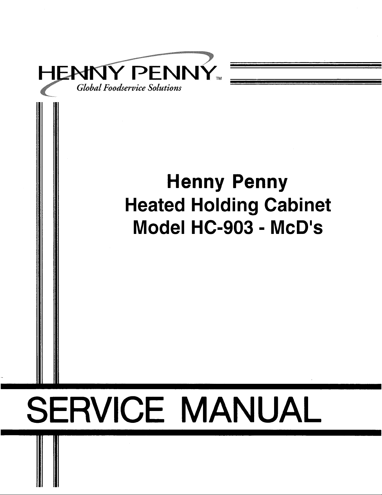
TABLE OF CONTENTS
WARRANTY STATEMENT ................................................. PAGE 2
INTRODUCTION ................................................................. PAGE 3
INSTALLATION .................................................................. PAGE 3
PARTS IDENTIFICATION ................................................... PAGE 4
EQUIPMENT SET-UP AND CLOSE PROCEDURES ........ PAGE 10
TROUBLESHOOTING ........................................................ PAGE 12
NON-SCHEDULED MAINTENANCE.................................. PAGE 13
ORDERING PARTS ............................................................ PAGE 20
FM01-688
Page 2
enny Penny Corporation makes the following
limited warranties to the original purchaser only
for Kenny Penny appliances and replacement
parts:
New Equipment
except lamps and fuses, which proves to be
defective in the material or workmanship within
1 year from date of original installation, will be
repaired or replaced without charge F.O.B.
factory, Eaton, Ohio, or F.O.B. authorized distributor. To validate this warranty, the registration card for the appliance must be mailed to
Henny Penny within 10 days after installation.
Replacement Parts
ment part, except lamps and fuses, which
proves to be defective in material or workmanship within 90 days from date of orginal installation will be repaired or replaced without
charge F.O.B. factory, Eaton, Ohio, or F.O.B.
authorized distributor.
This warranty covers only the repair or replacement of the defective part and does not include
any labor charges for the removal and installa-
tion of any parts, travel or other expenses
incidental to the repair or replacement of a part.
-Any part of a new appliance,
- Any appliance replace-
THE ABOVE LIMITED WARRANTY SETS
FORTH THE SOLE REMEDY AGAINST HENNY
PENNY FOR ANY BREACH OF WARRANTY OR
OTHER TERM. BUYER AGREES THAT NO
OTHER REMEDY (INCLUDING CLAIMS FOR
ANY INCIDENTAL OR CONSEQUENTIAL
DAMAGES) SHALL BE AVAILABLE.
The above limited warranty does not apply (a)
to damage resulting from accident, alteration,
misuse, or abuse; (b) if the equipment’s serial
number is removed or defaced; or (c) for lamps
and fuses. THE ABOVE LIMITED WARRANTY
IS EXPRESSLY IN LIEU OF ALL OTHER WARRANTIES, EXPRESS OR IMPLIED, INCLUDING
MERCHANTABILITY AND FITNESS, AND ALL
OTHER WARRANTIES ARE EXCLUDED.
HENNY PENNY NEITHER ASSUMES NOR
AUTHORIZES ANY PERSON TO ASSUME FOR
IT ANY OTHER OBLIGATION OR LIABILITY.
Should outside assistance be required, call your
local independent Henny Penny distributor. If
additional help is required, contact Henny Penny
Corporation direct in Eaton, Ohio.
Any claim must be presented to either Henny
Penny or the distributor from whom the appliance was purchased. No allowance will be
granted for repairs made by anyone else without
Henny Penny’s written consent. If damage
occurs during shipping, notify the carrier at once
so that a claim may be filed.
2
Page 3

INTRODUCTION
INSTALLATION
This staging cabinet is a basic unit of food
processing equipment designed to hold hot
foods at proper temperature in commercial
food operations. This cabinet will keep hot
foods humid while maintaining temperature.
Features:
• Easily cleaned
• Front panel programmable time and
temperature
• Easy access to Electrical Components
• Moist heat
• Removable control module
• Clear glass front door
• Lift out racks
• Venting system to limit humidity levels
in cabinet
WARNING: Do not puncture the skin of the
Staging Cabinet with any tools or fastening
devices. Electrical shock or component
damage could result.
The staging cabinet should be placed on an
approved table or shelf to allow easy access
for loading and unloading of product. For
proper operation, the cabinet must be level.
Electrical Connection
The Staging Cabinet is available from the
factory as a 120 VAC unit for domestic use, or
as a 240 VAC unit for foreign use. The data
plate on the side of the unit will specify the
correct electrical supply. The unit requires a
grounded receptacle with a separate electrical
line protected by a fuse or circuit breaker of
the proper rating.
WARNING: The cabinet must be adequately and safely grounded according to
local electrical codes to prevent the possibility of electrical shock.
Hazard Communication Standard (HCS) The procedure in this chapter include the
use of chemical products. These chemical products. These chemical products
will be highlighted with bold face letters
followed be the abbreviation (HCS). See
the Hazard Communication Standard
(HCS) Manual for the appropriate Material Safety Data Sheet(s) (MSDS).
This piece of equipment is made in America
and has American sizes on hardware. All
metric conversions are approximate and
vary in size.
Cabinet Preparation
When the cabinet is turned on for the first time,
you may experience the following:
A. A burning odor.
B. Slight smell of smoke.
This indicates oils used on stainless steel and
the new electrical connections are burning off
residue.
It will take 3 to 4 hours of burn off to eliminate
this inconvenience. The burning off procedure
should be done the day before you intend to
use the cabinet. It should be done in a ventilated area away from the kitchen and customers. After the burn off procedure is complete,
thoroughly clean the staging cabinet following
the daily cleaning procedures.
3
Page 4

1
2 12
3 (2) (4)
A C
14
13
11
10
9
4 (4) (4)
N O
7 (2)
56 8
B
PART
ITEM NO. DESCRIPTION QTY FUNCTION
1 25602 Module Top 1 Covering for components
2 52347 Control Panel Decal 1 Covering for digital display
3 27739 Strike Plate Only 1 Latches door closed
25937 Strike Plate & Latch Assy. 1
4 27154 Caster w/Brake 2 Allows unit to be mobile
27155 Caster 2
5 05030 Bun Pan Grid 5 Supports the product
6 05019 Bun Pan 5 Supports the grid
7 25702 Hinge Assy. 2 Allows the door to swing
27146 Chrome Hinge Cover Only 2 Covers hinge
8 54352 Glass Door Assy. - RH 1 Allows access to interior
54353 Glass Door Assy. - LH
41801 Glass Only 1 Allows viewing to interior
9 25793 Door Gasket 1 Seals the door to the unit
10 25957 Rack/Air Duct Assy. 2 Supports the pans and grids
11 25879 Water Box Assy. 1 Holds water for humidity
12 43768 Rocker Switch 1 Powers the controls
13 38367 Knob - Vented Module 1 Allows opening of vents
14 25704 Module Access Panel 1 Allows access to components
4
Page 5

15
20 (4) 17 (6) 18 (4) 19 16 (2)
J D D D
PART
ITEM NO. DESCRIPTION QTY FUNCTION
15 29523 Temperature Probe 1 Senses interior cabinet tem-
perature
16 ME90-003 Relay - 12 volt Coil 1 Routes power to heater
17 51117RB Display PC Board 1 Displays time and tempera-
ture
18 44741RB Control PC Board 1 Powers digital display and
temperature controls
19 40500 Replaceable Beeper 1 Sounds a tone when a button
is pressed and at the end of a
timing cycle
20 51115 Control Panel Weld Assy. 1 Sheet metal panel that control
components attach to
5
Page 6
25 24
26 23
27 (G) 22 (F)
4 4
28
21 (E)
2
PART
ITEM NO. DESCRIPTION QTY FUNCTION
21 TS22-006 Transformer - 115 volt 1 Reduces voltage to 12 volts
28979 Transformer - 240 volt 1
22 25738 Heater - 120 volt - 750 watt 2 Heats the cabinet
23 25964 Intake Hose 1 Pulls outside air into cabinet
24 28155 Vent Cable 1 Opens vents
25 ME50-021 Terminal Block 1 Junction for power cord
26 25963 Exhaust Hose 1 Allows interior cabinet air to
escape
27 18201 Temperature High Limit 2 Safety for overheating
28 25619 Blower Outlet Gasket 1 Seals blower to heater box
6
Page 7
29
30
(4) (4) (4) (4)
H I P Q
31
33
32
PART
ITEM NO. DESCRIPTION QTY FUNCTION
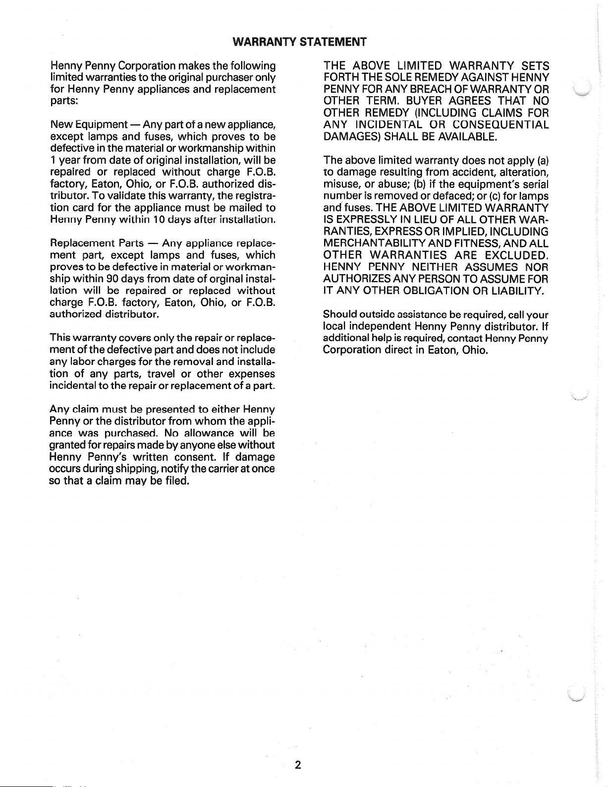
29 25706 Fan Blade 2 Cools the components
30 25751 Blower Motor - 120 volt 2 Circulates air in unit
25752 Blower Motor - 240 volt 2
31 25698 Blower Plate Gasket 4 Seals the blower housing to
the blower box
32 25627 Gasket 2 Seals the blower box to the
unit
33 25768 Fan Blade Spacer 2 Keeps fan blade at the correct
spacing on motor shaft
7
Page 8

28 (5)
K
29 (6) (6)
A L
30 (4)
M
31
PART
ITEM NO. DESCRIPTION QTY FUNCTION
28 25944 Rear Panel Studweld Assy. 1 Rear components attach to
29 25919 Vent Slide 1 Reduces voltage to 12 volts
30 25954 Outside Panel Assy. 1 Covers rear of unit
31 31584 Power Cord Assy. 1 Provides power to unit
8
Page 9

HARDWARE IDENTIFICATION
ITEM PART NO. DESCRIPTION QTY
A SC01-074 Screw #10-32 x 1/2” (12.5 mm) PH Thd S 16
B SC01-086 Screw #10-32 x 3/4” (18.8 mm) PH FHD S 16
C SC01-186 Screw #10-32 x 1 3/4” (43.8 mm) PH 16
D NS02-005 Nut Hex Keps #6-32 C 12
E SC02-012 Screw #10-AB 2
F SC04-003 Screw #8-32 x 3/8” (9.4 mm) PH PHD S 4
G SC02-035 Screw #10 x 1/2” (12.5 mm) AB PH PHD 410 SS 4
H SC01-091 Screw #6-32 x 5/16” (7.8 mm) SL RH 8
I LW02-010 Lockwasher - Internal #6 S 8
J SC02-030 Screw #8-B x 3/8” (9.4 mm) PH THS Black 4
K SC02-023 Screw 48-B x 3/8” (9.4 mm) PH THD 5
L NS02-001 Nut Hex Keps #10-32 C 5
M SC01-053 Screw #8-32 x 1/2” (12.5 mm) PH RHD S 4
N LW01-002 Lockwasher - Split 1/4” (6.3 mm) 16
O SC01-039 Screw 1/4-20 x 1” (25 mm) 16
P SC01-090 Screw #6-32 x 5/16 (8 mm) 4
Q* 25767 Spacer 4
* Not Shown
9
Page 10

EQUIPMENT SET-UP AND
CLOSE PROCEDURES
The Introduction and Installation sections of
this manual should be read before operating
the cabinet.
Vent Adjustment
The vent setting corresponds to the number of
trays of product. With one tray of product, set
the vent at No. 1. With two trays of product, set
the vent at No. 2, and so on.
This section contains an explanation of all
controls and components and information
on operating procedures and daily maintenance.
Heated air inside the cabinet is circulated
over 2 heating coils and across a water pan.
The warm, moist air is then forced downward through air ducts on each side of the
unit. The heated air is dispersed over and
under the product from openings in the air
ducts. These openings are varied in size to
promote uniformity of heated air throughout
the cabinet.
Set-up
Place the power switch in the ON position.
If humidity is desired, remove the water pan
and put approximately 1” of hot water in the
pan. Then return the pan to the unit.
Close
Daily Cleaning Procedure
1. Move the power switch to the OFF
position.
2. Disconnect the electrical supply to the
cabinet.
WARNING: Allow the unit to cool before
cleaning by opening the door(s) slightly.
3. Remove trays and racks from the inside of
the unit and clean them thoroughly with a
hot solution of McD All Purpose Concen-
trate (APC) (HCS) from the sink
proportioner.
CAUTION: Most surfaces of the unit can be
cleaned with a soft cloth, cleanser, and
water. DO NOT USE ABRASIVE CLEANERS.
NOTE: Be sure to push the water pan in
as far as it will go so that it does not
block air from the temperature probe.
This will assure proper operation of the
controls.
The display will increase in temperature,
indicating the cabinet is heating. When the
operating preset temperature is reached the
“HEAT ON” LED will turn off and the display
should stay at the preset temperature.
Once the preset temperature shows on the
display, product can then be placed in the
cabinet. Slide a tray of product into the
racks, close the door, and press the appropriate timer button on the controls.
4. Remove the water pan and clean it with a
soft cloth and a hot solution of McD APC
(HCS) from the sink proportioner.
5. Wipe the control panel with a damp cloth.
Do not splash water around the controls.
6. Clean the exterior of the cabinet with a
damp cloth.
NOTE: The doors can be easily pulled from the
hinges for easy cleaning.
7. Clean the interior of the cabinet thoroughly
with a cloth and a hot solution of McD APC
(HCS) from the sink proportioner.
8. Put the side racks and water pan back into
the cabinet.
9. Leave the door open over night to allow the
unit to dry out.
10
Page 11

Temperature Regulation
It is possible to regulate the setpoint temperature. Depress and hold the PROGRAM
button for one second, then the control
beeps and the top display shows “Prog,”
release the button. The top display will now
show “Prog Enter Code.” Enter access
code 1-2-3. The setpoint temperature will
now start blinking in the display and the
setpoint can now be changed be depressing
the Increase and Decrease buttons. Press
and hold the Program button to exit Program Mode.
3. Enter access code 1-2-3. “Setup deg. “F”
shows in the display.
Fahrenheit or Celsius
Once in the Setup Mode, and “Setup deg. F”
shows in the display, depress the Increase or
Decrease buttons. The display will toggle from
Fahrenheit and Celsius (F
o
or Co). When the
correct setting is displayed, depress and release the Program button to move the next item
in the Setup Mode, or depress and hold the
Program button to exit the Setup Mode and
return to normal operation.
Timer Operation
Each of the 5 timers operate independently
of each other and may be started, stopped,
or aborted regardless of the status of the
other timers. By depressing the desired
timer button, the timer display will show the
time remaining at the end of the timing cycle
an alarm will sound and “0:00” will flash in
the dimer display. Depressing the timer
button, the timer display will show 3 dashes
(“---”).
To cancel a timer before it counts down,
depress and hold the timer button.
Special Program Mode
The Special Program Mode consists of a
Setup Mode and a Tech Mode.
The Setup Mode accesses the following
features:
Initialize System
The next item in the Setup Mode is the initialize
system step. This step completely resets the
control back to factory settings. “Setup init sys”
shows in the display. To perform the initialize
operation, press and hold either the Increase or
Decrease button. The control will start beeping
and display will start counting down from “5”.
Once the control reaches “0”, the Increase or
Decrease button can be released, and the
initialization is complete.
If the Increase or Decrease button is released
before the count down reaches ”0”, the control
will not initialize.
Depress and release the Program button to
return to the Fo /Co step, or depress and hold
the Program button to exit the Setup Mode and
return to normal operation.
Tech Mode
1. Fahrenheit or Celsius.
2. Initialize System - a one button programming for times and temperatures.
To enter the Setup Mode:
1. Depress and hold the Program button
for at least 4 seconds. Setup and Tech
will show in the display.
2. Depress the timer button under the
word Setup. Ex: “Setup”, depress
either 1 or 2.
The Tech Mode accesses the following features:
1. Output test - Heaters
2. CPU Calibration
3. Temperature Probe Calibration
4. Display Tests
5. Push-buttonTest
6. Total Initialization
11
Page 12

NOTE: The Tech Mode is mostly for use
at the factory level. The output tests and
temperature probe calibration is given
below. For further information on the
other features, call the Service Department at Henny Penny Corp.
To enter the Tech Mode:
1. Depress and hold the Program button
for at least 4 seconds. Setup and Tech
will show in the display.
2. Depress the timer button under the
word Tech. Ex: “Tech”, depress either
4 or 5.
Temperature Calibration
After the code has been entered in the Tech
Mode, depress and release the Program button
3 times, “CAL OFS Hi Probe 185
o
shows in the
display. Depress and hold the number 1 timer
button under “CAL”, while depressing the
Increase or Decrease buttons. This enables
the operator to set the display to match the
actual cabinet temperature.
Depress and release the Program button to
move to the next step or depress and hold the
Program button to exit the Tech Mode.
Physical Specifications
3. Enter the access code 1-1-2-2-1-1-2-2.
“Output test Htr” will show in the display.
Outputs Tests
• 24 3/4” wide x 31 3/4” deep x 37” high (63 x
81 x 97 cm). Model HC-903 with 5 count
down timers
• Accepts 18” x 26” (46 x 66 cm) bun pans and
grids
Depress the number 5 timer button (under
“Htr”) to toggle the heat output and the heat
• Shipping weight - 200 lbs. (90.8 kg.)
LED on and off.
TROUBLESHOOTING
Depress and release the Program button to
move to the next step, or depress and hold
the Program button to exit the Tech Mode.
CAUTION: Refer to maintenance procedures in the Non-Scheduled Maintenance
section to check and repair the unit safely
and properly.
Operation
PROBLEM PROBABLE CAUSE CORRECTIVE ACTION
Product not holding Doors are left open. Keep doors closed except to load and
temperature and serve product.
Temperature set too low. Increase the temperature by depressing
the Program button, enter 1-2-3, and
use the Increase or decrease buttons.
Door gasket torn or worn. Replace gasket.
Heater not working. Check heater and replace if necessary.
Blower not working. Check blower and replace if necessary.
Product held too long. Hold product only for recommended
time.
Low or improper voltage Using a meter, compare receptacle
voltage to data plate voltage.
Error message E06. Faulty temperature probe . Replace temperature probe.
12
Page 13

PROBLEM PROBABLE CAUSE CORRECTIVE ACTION
Product becoming Too much humidity inside the Empty water from the water pan.
soggy. cabinet.
Holding product too long. Hold product for recommended time.
Vent not set properly. Set vents per recommended procedure.
Product Dry. No water in pan. Remove pan and put in approximately
1” of hot water.
Heating System
PROBLEM PROBABLE CAUSE CORRECTIVE ACTION
Unit will not heat to Faulty blower. Check blower and replace if necessary.
desired temperature. Display not indicating correct Check cabinet temperature with a ther-
temperature. mometer. If the temperature is within
10o F (12o C) of the display, proceed
with the calibration procedure. If more
than 10
o
F (12o C), replace the tempera-
ture probe.
One of the heaters defective. Check heater and replace if necessary.
Doors being left open too much. Only open doors as necessary.
Door gaskets torn or worn. Replace door gasket.
Defective high limit on one of Check high limit, replace if necessary.
heaters.
Unit Overheating Faulty control. If heat LED stays on past setpoint
temperature, try to re-initialize the
controls. If that fails, replace control.
Faulty blower. Check blower and replace if necessary.
Error message HI Cabinet temperature exceeds To reset , turn power switch OFF and
hi-limit range. then ON.
Ventilating System
PROBLEM PROBABLE CAUSE CORRECTIVE ACTION
Both blowers not Faulty blowers. Check blower and replace if necessary.
working. Faulty fuse. (If unit is Check fuse and replace if necessary.
equipped with fuse)
NON-SCHEDULED MAINTENANCE
When the manual refers to the circuit being
open, the continuity light will not illuminate or
TESTING INSTRUMENTS
You may use 2 instruments to check the
electric components.
the ohm meter will read 1 or infinite resistance.
NOTE: A continuity tester cannot be used to
check coils.
1. A Continuity Light.
2. An Ohm Meter.
13
Page 14

ACCESS PANEL
Tools: Phillips screwdriver
In most procedures of the maintenance
section, the access panel must be removed
from the top of the module. This access
panel can easily be removed by taking out
the four screws that fasten it to the module
shell.
2. Remove the 6 side screws.
3. Remove the 4 top screws.
MODULE HOUSING REMOVAL
Tools: Phillips screwdriver
In some procedures the complete module
top will need to be removed to allow better
access to some components.
1. Remove the front and back panel
screws.
4. Pull module top from unit.
POWER SWITCH
1. Disconnect the electrical supply to the
cabinet.
WARNING: Place the power switch in the
OFF position and unplug the power cord.
Failure to do so could result in electrical
shock.
2. Remove the module housing.
3. Squeeze in on the clips which hold the
switch in place and pull out from the front.
14
Page 15

3. Label and remove the wires from the
switch. Check across the terminals - top
and bottom terminals on the left side of
the switch, and top and bottom terminals
on the right side. In the ON position the
switch should show continuity. If switch
is defective, replace it and proceed with
procedures.
4. Replace with new switch in reverse
order and reconnect power to unit.
3. Open the door to the unit and remove the
screws securing the probe to the module.
4. Remove the nuts securing the blower box
and pull the probe from under the box.
PROBE REPLACEMENT
In the event the temperature probe
becomes faulty, an error message E06
will be displayed. Turn the power switch
OFF and then back ON. If the error
message E06 is still displayed, the
temperature probe must be replaced.
Tools: Phillips screwdriver, 3/8” (9 mm)
socket
1. Disconnect the electrical supply to the
cabinet.
WARNING: Place the power switch in
the OFF position and unplug the power
cord. Failure to do so could result in
electrical shock.
2. Remove the module housing.
5. Unplug the probe from the PC board.
6. Install the new probe in reverse order and
restore power to the unit
15
Page 16

CONTROL BOARD REPLACEMENT
DISPLAY BOARD REPLACEMENT
Tools: 5/16” (8 mm) wrench or socket,
Phillips screwdriver
1. Disconnect the electrical supply to the
cabinet.
WARNING: Place the power switch in
the OFF position and unplug the power
cord. Failure to do so could result in
electrical shock.
2. Remove the screws securing the front
panel.
Tools: 5/16” (8 mm) wrench or socket,
Phillips screwdriver
1. Disconnect the electrical supply to the
cabinet.
WARNING: Place the power switch in the
OFF position and unplug the power cord.
Failure to do so could result in electrical
shock.
2. Remove the screws securing the front
panel.
3. Remove the control board.
4. Remove the 4 nuts securing the display
board to the unit and remove the board from
the unit.
3. Unplug the control board from the
display board.
4. Remove the 4 nuts securing the control
board to the display board and remove
the board.
5. Install new board in reverse order, being
careful when tightening nuts on the
board. Then restore power to the unit.
5. Install the new board in reverse order and
restore power to the unit.
REPLACEABLE BEEPER
Tools: Phillips screwdriver
1. Disconnect the electrical supply to the
cabinet.
WARNING: Place the power switch in the
OFF position and unplug the power cord.
Failure to do so could result in electrical
shock.
16
Page 17

2. Remove the screws securing the front
panel.
3. Carefully pull the blue beeper straight
back off of the control board.
4. Line up prongs of new beeper with the
terminals on the control board and firmly
press beeper onto board.
4. Remove the two screws securing the transformer to the unit and remove the transformer from the unit.
5. Install the new transformer in reverse order
and restore power to the unit.
5. Replace screws in the front panel and
restore power to the unit.
TRANSFORMER REPLACEMENT
Tool: Phillips screwdriver
1. Disconnect the electrical supply to the
cabinet.
WARNING: Place the power switch in
the OFF position and unplug the power
cord. Failure to do so could result in
electrical shock.
2. Remove the module housing.
3. Label and remove the wires from the
transformer.
BLOWER REPLACEMENT
Tools: Phillips screwdriver
1. Disconnect the electrical supply to the
cabinet.
WARNING: Place the power switch in the
OFF position and unplug the power cord.
Failure to do so could result in electrical
shock.
2. Remove the access panel from the module.
3. Disconnect the wires to the blower.
3. Remove the three screws securing the
blower motor to the housing and pull the
motor from the housing.
17
Page 18

NOTE: The blower motor can be ordered
as an assembly. This will include the motor,
the fan, and the wheel. Normally, just the
motor would need replacing if found to be
defective. If you are just replacing the
motor, continue with the following procedures.
4. The fan blade can be pulled off the shaft
of the motor.
5. With a 5/64” Allen wrench, loosen the
set screw that holds the blower wheel to
the motor shaft and remove the wheel.
HEATER REPLACEMENT
Tool: Phillips screwdriver
1. Disconnect the electrical supply to the
cabinet.
WARNING: Place the power switch in the
OFF position and unplug the power cord.
Failure to do so could result in electrical
shock.
2. Remove the access panel.
3. Remove the wires to the heater.
6. Remove the 4 screws securing the
blower cover to the motor.
NOTE: When replacing a blower motor, be
sure that the motor coil is positioned away
from the heater when reinstalling.
7. Install the new blower motor in reverse
order and restore power to the unit.
4. Remove the 2 screws securing the high
limit.
5. Remove the 2 screws securing the heater
and remove the heater from the unit.
6. Install new heater in reverse order and
restore power to the unit.
18
Page 19

HIGH LIMIT REPLACEMENT
DOOR GASKET REPLACEMENT
Tools: Phillips screwdriver
1. Disconnect the electrical supply to the
cabinet.
WARNING: Place the power switch in
the OFF position and unplug the power
cord. Failure to do so could result in
electrical shock.
2. Remove the access panel from the top
of the cabinet.
3. Remove the wires attached to the high
limit.
tools: Phillips screwdriver
1. Pull the gasket to the side to expose the
screws that hold the retainer to the cabinet.
2. Loosen the screws around the full outside
perimeter of the gasket.
4. Remove the two screws that hold the
high limit to the heater and remove high
limit..
5. Install the new high limit in reverse
order.
3. With screws loose, the gasket should slide
out from under the retainer.
4. Install new gasket in reverse order.
RELAY REPLACEMENT
Tools: 5/16” (8 mm) socket or wrench
1. Disconnect the electrical supply to the
cabinet.
WARNING: Place the power switch in the
OFF position and unplug the power cord.
Failure to do so could result in electrical
shock.
2. Remove the screws to the control panel.
19
Page 20

3. Label and disconnect the wires to the
relay.
4. Remove the nuts securing the relay and
remove the relay from the panel.
How to Order
Once the parts you want to order have been
found in the parts list, write down the following
information:
1. From the photography and parts list:
Item Number ________________________
Part Number ________________________
Description _______________________
2. From the data plate:
Product Number _____________________
5. Install new relay in reverse order.
ORDERING PARTS
This section identifies and lists the replaceable parts of the Henny Penny staging
cabinet.
Use only genuine Henny Penny replacement parts in your cabinet. Using a substitute design may result in cabinet damage or
personal injury.
To find items you want to order from the
Parts List, proceed as follows:
1. Refer to the photographs in the front of
the Operating Procedures section to
identify the part needed.
2. Use the item number from the photos
then locate the corresponding part in the
parts list below the photo. In this list will
be the Henny Penny part number and a
description of the part.
Serial Number ____________________
Voltage ____________________
3. The following table has been provided as a
sample format for you to use in preparing
your spare parts orders. By providing all the
entries, your distributor will be able to
ensure the correct parts will be sent to you.
Commonly replaced items are stocked by your
distributor and will be sent when your order is
received. Other parts will be ordered by your
distributor from Henny Penny Corporation.
Normally, these will be sent to your distributor
within 3 working days.
Refer to the warranty statement found at the
beginning of this manual.
FROM PARTS LIST YOUR ORDER
Item Part Quantity
Number Number Description Ordered Price Each Total
Product No. ________________ Serial No. ___________________ Voltage ________________
Fill-in for your records
20
Page 21

21
Page 22

Page 23

For Sales or Service Please Contact
The Nearest Henny Penny Distributor
1. General Services
100 Hicks Ave.
Medford, MA 02155
(800) 233-1033
2. Art Cole Associates
Golden Street
Industrial Park
Meriden, CT 06450
(203) 237-7177
3. Globe-Monte Metro, Inc.
47-02 Metropolitan Avenue
Ridgewood, NY 11385
(718) 786-5760
4. Guertin Dist. Inc.
5 Technology Drive
East Syracuse, NY 13057-9713
(315) 437-4928
(800) 468-6336
5. Kreiser Distributing Co.
13800 Lincoln Highway
N. Huntington, PA 16652
(724) 863-3360
6. AFS Equipment Company
9130-X Red Branch Road
Columbia, MD 21045
(410) 964-3770
(800) 969-3770
7. HP Sales & Service Co.
200 Rittenhouse Circle, 4-East
Bristol, PA 19007
(215) 785-3250
NJ Watts (800) 477-4379
8. Astro Food Equipment
7901 Old Rockside Rd.)
Independence, OH 44131
(216) 619-8821
(800) 367-4237
9. Carlisle Food Systems, Inc.
11020 Lakeridge Pkwy.
Ashland, VA 23005
(804) 550-2169
10. Price-Davis, Inc.
Route 1, Highway 27
Iron Station, NC 28080
(509) 928-8815
(704) 732-2236
(800) 456-1014
11. Big A Distributors, Inc.
P.O. Box 1283
Forest Park, GA 30051
(404) 366-6510
(800) 222-0298
12. W.H. Reynolds
Distributors, Inc.
4817 Westshore Blvd.
Tampa, FL 33609
(813) 873-2402
Miami-(954) 845-0841
Jacksonville-(904) 781-9054
FL Watts (800) 282-2733
13. Ber-Vel Distributing Co. Inc.
P.O. Box 9943
Birmingham, AL 35220
(205) 681-1855
14 . Barnett Supply
2089 York Ave.
Memphis, TN 38104
(901) 278-0440
Nashville, TN
(615) 242-6451
Scotsman Supply
516 5th Ave., South
Nashville, TN 37203
(615) 242-6451
15. St. Clair Supply Company
231 East Main Street
Eaton, OH 45320
(937) 456-5500
(800) 762-2968
16. Dine Equipment Co.
3110 Preston Hwy.
P.O. Box 34038 zip 40232
Louisville, KY 40213
(502) 637-3232
FAX (502) 637-5177
17. United Marketing Assoc.
11877 Belden Court
Livonia, MI 48150
(734) 261-5380
18 . T&H Distributors
1235 Parkview
Green Bay, WI 54304
(920) 339-9838
19. Food Service Solutions, Inc.
1682 Barclay Blvd.
Buffalo Grove, IL 60089
(847) 459-8040
(847) 459-7942
20. MEC
2511 Cassens Dr.
Fenton, MO 63026-2547
(636) 343-0664
(800) 397-1515
21. Delta Supply Co., Inc.
3315 W. Roosevelt Rd.
Little Rock, AR 72204
(501) 664-4326
22. Dixie Supply
490 Julianne St.
Bldg. A-2
Jackson, MS 39201
(601) 354-3025
23. Beaullieu Refrigeration Inc.
200 North Luke St.
Lafayette, LA 70506
(337) 235-9755
24. S.L.E. Corporation
1110 Avenue H East
Arlington, TX 76011
(817) 640-7999
25. Brooks Industries
4420 S.W. 29th St.
Oklahoma City, OK 73119
(405) 685-7200
26 . B & D Dist.
19915 W. 161st St.
Suite D
Olathe, KS 66062
(913) 768-8588
FAX 913-768-8855
27 . PHT Systems
1801 Highway 8
Suite 120
New Brighton, MN 55112
(651) 639-0368
28. Mid-Nebraska Restaurant
Supply Co.
1415 S. Webb Road
Grand Island, NE 68802
(308) 384-5780
29. Robert G. Wood & Co.
2080 W. Cornell Ave.
Englewood, CO 80110
(303) 761-0500
(800) 358-3061
30. Open Territory
31 . CPE-USALCO
1310 West Drivers Way
Tempe, AZ 85284
(480) 496-6995
32. National Equipment Corp.
242 West-3680 South
Salt Lake City, UT 84115
(800) 266-5824
(800) 955-9202
33. The Nicewonger Co.
19219 West Valley Hwy
Suite M103
Kent, WA 98032
(800) 426-5972
(425) 656-0907 FAX
34. Tri-State Market Supply
11115 E. Montgomery, Suite A
Spokane, WA 99206
(509) 928-8815
(877) 828-4268
36. Western Pacific
Distributors, Inc.
19422 Cabot Boulevard
Haywood, CA 94545
(510) 732-0100
37. Don Walters Company
2121 S. Susan Street
Suite A
Santa Ana, CA 92704
(714) 979-5863
38 . Troyer Foods, Inc.
17141 State Route 4
Goshen, IN 46526
(219) 533-0302
39. Tri-City HP, Inc.
527 West Fourth St.
Davenport, IA 52801
(319) 322-5382
40. Certified Commercial Service &
Equipment (CCSE)
6031-A Industrial Heights Drive
Knoxville, TN 37909
(865)-546-8778
41 . Gower Distributors, Inc.
P.O. Box 4804
Box 216K Rt. -4
Victoria, TX 77903
(361) 573-9777
42 . Top-Line Distributors
1501 College Ave.
Houston, TX 77585
(713) 946-6008
43. DSL Inc., Canada
14520 128th Ave.
Edmonton, Alberta
Canada T5L3H6
(403) 452-7580
(Alberta, British Columbia,
Manitoba, Saskatchewan,
Yukon, & N.W. Territories)
44. Taylor Freezers, Inc.
52 Armthorpe Rd.
Brampton, Ontario
Canada L6T5M4
(905) 790-2211
(Ontario, Montreal, and
Maritime Provinces)
45. Bazinet Taylor Ltee.
4750 Rue Bourg
Ville St. Laurent
Quebec, Canada H5T 1J2
(514) 735-3627
(Quebec only)
If Further Assistance Is Needed Please Contact: Henny Penny Corporation
1219 U. S. Route 35 West
Eaton, Ohio 45320
1-800-417-8417
Fax 1-800-417-8402
Revised 4-01
Page 24

Page 25

Henny Penny International Distributor Network
U.S. Headquarters
Henny Penny Corporation
1219 U.S. Route 35 West
Eaton, OH 45320 USA
Telephone: 937-456-8417
Fax: 937-456-1860
Representative Office
1 . Henny Penny Corporation
Representative Office
Parc dEntreprises de
IEsplanade
2bis Rue Paul Henri Speak
Saint Thibault des Vignes
77462 Lagny sur Mame Cedex,
France
Telephone: 33 (1) 60075600
Fax: 33 (1) 60071489
U.S. Export Centers
2. Feco International Company
20 North San Mateo Drive,
Suite 9
San Mateo, CA 94401 USA
Telephone: 415-348-3499
Fax: 415-348-3575
3. Caribbean Islands & Central
America (excluding Puerto Rico)
Total Equipment Suppliers
9550 NW 41
Miami, FL 33178
Telephone: 305-718-9550
Fax: 305-718-9505
Algeria
4. SOMAB
Y1 Rue Mahmoud Boudjatit
(Oasis) Ager, Algeria
Tel: 213-21-23-3051/3052
Fax: 213-21-23-3161
Argentina
5. Oditec S.A.
Augstin Alvarez 2128
1602 Florida
Buenos Aires, Argentina
Telephone: (541) 796-0820
Fax: (541) 796-2009
6. Australia
J.L. Lennard Pty. Ltd.
937-941 Victoria Rd.
West Ryde NSW 2114
Sydney, Australia
Telephone: 617-3272-4744
Fax: 617-3272-4799
Bahrain
7. Mohammed Jalal Catering
Old Palace Road
P.O. Box 1335
Manama, State of Bahrain
Telephone: 973-53-45-39
Fax: 973 53-14-78
Bangladesh
8. Puffin International Ltd.
3691B Elephant Rd.
Swarankika Plaza
4th Floor-Dhaka 1205
Dhaka, Bangladesh
Telephone: 8802-863117
Fax: 880-2-867563
Belgium
9. Engelen-Heere N.V.
Industrialpark Terbekehof
Fotografielaan 14
B-2610 Antwerpen (Wilrijk)
Telephone: 323-825-5577
Fax: 323-825-3702
st
St.
Brazil
10. Pesin Equipment Food Service
R. Olavo Bilac 188/198
Sao Caetano Do Sul - SP
Brazil
Telephone:55-11-7690-1470
Fax: 55-11-7690-1466
Bulgaria
11. E.C.E. - CAIX
23A Rue Oborichte
Sofia 1604, Bulgaria
Telephone: 19-359-2-946-1479
Fax: 19-359-2-946-1669
Chile
12. IMAHE
Manuel Montt 1154 Providencia
Santiago, Chile
Tel: 562-341-4953/5707
Fax: 562-274-8567
China
13. Bonny Foodservice Products
Flat C, 8/F, Yeung Yiu Chung
Industrial Bldg., No. 20
Wang Hoi Rd.
Kowloon Bay, Kowloon Hong Kong
Telephone: 852-796-5616
Fax: 852-799-8490
Colombia
14. Industrial Taylor Ltda.
Transversal 93, Numero 64-24
Apartado Aereo 95075
Bogota D.E., Colombia
Telephone: 57 (1) 4340016
Fax: 571-223-2642
Crotia
15. New Rok
Opatija M. Tita 15
51410 Opatija, Crotia
Telephohe: 385-51-701-251
Fax: 385-51-701-251
Cyprus
16. AMF Chistofides Ltd.
104A Prodromos Str.
P.O. Box 25100
Nicosia, Cyprus
Telephone: 357-2-454-380
Fax: 357-2-454-088
Czech Republic
17. Citus
Argentinska 20
CZ 4170 00 Pragues 7
CZECH REPUBLIC
Telephone: 420-2-667-10-561
Fax: 420-2-667-10-557
Denmark
18. Inter-Gastro A.S.
Midtager 18
2605 Brondby
Denmark DK2605
Telephone: 45-43292000
Fax: 45-43292001
Ecuador
19. Equindeca Cia. Ltda.
Hotel El Conquistador
Gran Colombia 6-65
Cuenca, Ecuador
Telephone: 593-7-831788
Fax: 593-7-843221
Egypt
20. Con Trade Centre
3A Ramsis Street
Maaroof Building #83 & #62
Cairo, Egypt
Telephone: 20 (2) 770642/762551
Fax: 20 (2) 756258
Estonia
21. Sisustaja As
Tihniku 5
11625 Tallinn, Estonia
Telephone: 372-6502300
Fax: 372-6502301
Finland
22. Monilaite Oy
P.O. Box 27
Salpakuja 6
SF-01200 Vantaa, Finland
Telephone: 358-9-877-0100
Fax: 358-9-877-01099
France
23. Diffusion International de
Materiel (DIM)
Parc dactivite Clemenceau
Chemin du Chateau dEau
B.P. 4009
59704 Marcq-En-Baroeuil
Cedex, France
Telephone: (33) 20890000
Fax: (33) 20727355
Germany
24. Sesjak KG
Wullener Feld 9a
D-58454 Witten
Germany
Telephone: 49-2302-697077
Fax: 49-2302-698451
Ghana
25. DRT Ghana
E6619 Ablade Road
Kanda Estate
P.O. Box C2074
Accra-Cantonments, Ghana
Telephone: 233-2123-3949
Fax: 233-2123-1380
Greece
26. Domestica S.A.
65 Stournara Str.
Athens 10432, Greece
Telephone: 30-15-24-30-14/15
Fax: 30-15-22-91-58
Guam
27. Pacific Technical Service, Inc.
New Commercial Building
#979 Rt. 16, Suite B-3
Barrigada, Guam 96913
Telephone: 6710632-5000
Fax: 671-632-3333
Holland
28. Englelen-Heere B.V.
Straatveg 85, Postbus 35020
3005 DA Rotterdam, Holland
Telephone: 311-042-23077
Fax: 311-042-23435
Hong Kong
29. Bonny Foodservice Products
Flat C, 8/F, Yeung Yiu Chung
Industrial Building #20
Wang Hoi Road
Kowloon Bay, Kowloon,
Hong Kong
Telephone: 852-796-5616
Fax: 852-799-8490
Hungary
30. Hotex Service
H-2094 Nagykovacsi
Kossith Lajos u. 1.
Hungary
Telephone: 36-263-56653/89463
Fax: 36-26389463
Iceland
31. A. Karlsson H. F.
Brautarholti 28
105 Reykjavik, PO Box 167
Iceland
Telephone: 354-560-0900
Fax: 354-560-0901
India
32.
AISHWARYA
Trust Complex, 10 OVG Rd
Basavanagudi
Bangalore 560004, India
Telephone: 91-80-667-7576
Fax: 91-80-667-7576
Intl. Refrigeration Corp
7 Netaji Subhash Marg
Darya Ganj
New Delhi 110002, India
Telephone: 91-11-3275651
Fax: 91-11-6221827
Indonesia
33. P.T. Gema
JL. Raya Bloulevard Raya
Block IOA 2 No. 27
Kelapa Gading Permai
Jakarta 14240, Indonesia
Telephone: 62-21-4532077
62-21-4508910
Fax: 62-21-4532586/4530777
Ireland
34. Martin Food Equipment Ltd.
Gaskin Business Park
Coes Road
Dundalk, Louth County
Ireland
Telephone: 353-42-30366
Fax: 353-42-30370
Italy
35. Allegra SRL
Corso Matteotti, 5 - 10121
Torino, Italy
Telephone: 39-011-540264
Fax: 39-011-533779
Japan
36. Toei Kogyo Co. Ltd.
4F, Nissay Nishi-Gotanda
Building 24-5
Nishi-Gatanda 7-Chome
Shinagawa-ku, Tokyo 141-0031
Japan
Telephone: 813-3779-1081
Fax: 813-3779-1638
Jordan
37. Awar Trading Est
PO Box 962227
Amman 11196, Jordan
Telephone: 962-6-55-19-610
Fax: 962-6-55-19-605
Korea
38. Ohjin Corporation
3rd Floor, Hee Jung Building
1635-0 Seocho-dong
Seocho-ku
C.P.O. Box 3252
Seoul 137-070, Korea
Telephone: 82-2-5850441
Fax: 82-2-5874197
Kuwait
39. Mabrook Hotel Supplies Co.
PO Box 43832 Hawalli
32053 Kuwait
Telephone: 965-481-8242
965-483-01648
Fax: 965-483-4314
Revised 5/01
Page 26

Lebanon
40. Pro Kitchen
Cahlfoun Building
Kaslik - Main Road
PO Box 1066 Jounieh
Lebanon
Telephone: 961-9-635-077
Fax: 961-9-635-059
Lithuania
41. Master Group Baltic Master
Dariaus Ir Girena 175
2038 Vilnius, Lithuania
Telephone: 3702-306-528/529
Fax: 3702-306-533
Malaysia
42. SCC Corp. Sdn. Bhd.
19-21 Jalan Hujan
Taman Overseas Union
58200 Kuala Lumpur,
Malaysia
Telephone: 60-3-77828384
Fax: 60-3-77818561
Malta
43. C & H Bartoli Ltd.
232 The Strand
Gzira Gzros, Malta
Telephone: 356-342-584
Fax: 356-342-569
Mauritius Island
44. (Mauritius, Reunion Island,
Seychelles)
Hassam Moussa Rawat
10 Bourbon Street
P.O. Box 492
Port Louis, Mauritius Island
Telephone: 160 (230) 2080024
Fax: 160-230-2080147
Mexico
45.
Central Mexico Metro Mexico City
Cavimex S.A. de C.V.
Revillagigedo No. 61 Col Centro
Mexico, D.F. 06070
Mexico
Telephone: 525-521-4200
Fax: 525-510-2791
Pacific
Micro Herros De Occidente,
S.A. de C.V.
Av. Juan Palamar y Arias
#83 Col. Jardines Vallarta
Zapopan, Jalisco, Mexico
C.P.45020
Telephone: 52-3-629-54-05
Fax: 52-3-673-29-43
Southeast
Equipo Para El Mercado
S.A. de C.V
Calle 55 No. 501-B por 60 y 62
Merida, Yucatan,
Mexico C.P. 97000
Telephone: 52-99-236500
Fax: 52-99-286649
Morocco
46. Electra
Boulevard AHL Loghlam
BP 25698
Sidi Bernoussi - Ain-Sebaa
Casablanca Morocco
Telephone: 212-22-753-531
Fax: 212-22-753-554
New Zealand
47. Taylor Equipment Limited
4 Ponuz Place
Mt. Wellington
Auckland, New Zealand
Telephone: 64 (9) 5733377
Fax: 64 (9) 5730841
Norway
48. Grillfagmannen A.S.
Ostensjoveien 44
N-0667 Oslo 6, Norway
Telephone: 47 (2) 651410
Fax: 47 (2) 720017
Oman
49. Mohsin Haider Darwish LLC
P.O. Box 880
Ruwi, Code 112
SULTANATE OF OMAN
Telephone: 968-703411
Fax: (968) 789927
Pakistan
50. The Equipment Company
Ground Floor, Dadabhoy Centre
Sharea Faisai, Karachi 75530
Pakistan
Telephone: 922-1-778-1778/2778
Fax: 922-1-587-0456/778-2777
Peru
51. Importadora Tecnica
Comercial C.R. Ltda.
Jr. Marcos de Aramburu #595
Lima 17, Peru
Telephone: 51-1-226-2124
Fax: 51-1-275-2689
Philippines
52. HKR Equipment Corp.
2nd Floor, THC Bldg.
2176 Primo Rivera St.
La Paz, Makati City, Philippines
Telephone: 632-899-4511
Fax: 632-899-4541
Poland
53. I. F. E.
Rydygiera 12
01 793 Warsaw, Poland
Telephone: 48-3912-3373
42-22-663-4820/4069
Fax: 48-3912-3373
Portugal
54. Restaurotel
AV Da Republica
83 C 1050
243 Lisboa
Portugal
Telephone: 351 7967116/7/8/9
FAX: 351 7933982
Puerto Rico
55. Progressive Sales and Service
PO Box 10876
Caparra Heights Station
San Juan, Puerto Rico 009220876
Telephone: 787-782-7474
Fax: 787-793-6479
Qatar
56. Tristar Group
C.R. No. 6778
P.O. Box 4746
Doha, Qatar
Telephone: 974-4664433
Fax: 974-4365365
Romania
57. Delta Technologies Romani S.A.
Sector 6, 20 Constructorilor Blvd.
Bloc 20 A, sc. B 7th Floor
Apt. 64
Bucharest, D599 Romania
Telephone: 401-220-4261
Fax: 401-220-3990
US Address:
115 Main St.
Mishawaka, In. 46544
Telephone: 219-256-3783
Fax: 219-256-7130
Saudi Arabia
58. Commercial Center
Development & Economy
P.O. Box 1210
Jeddah 21431, Saudi Arabia
Telephone: 966 (2) 629-1857
Fax: 966 (2) 629-1860
Senegal
59. Breading Systems Co.
C/ Ripoche,14
35007 Las Palmas
Spain
Telephone: 34-9-28-22-43-86
Fax: 34-9-28-27-56-90
Singapore
Simplex Pte. Ltd.
60.
Block 1, Lorong 8
Toa Payoh Industrial Park 01-1383
Singapore 319053
Telephone: 65-251-6241
Fax: 65-253-8814
Shopfit (S) Pte. Ltd.
Blk 623 Aljunied Industrial Complex
Unit 02-09
Singapore 389835
Telephone: 65-7410911
Fax: 65-7438911
South Africa
61. Foodserv CC
PO Box 55269
Northlands 2116,
Republic of South Africa
Telephone: 27 (11) 616-5183,
Fax: 27 (11) 616-8287
Spain
62. Adisa
Tuset, 8-10
08006 Barcelona, Spain
Telephone: 34-93-415-0018
Fax: 34-93-218-1782
Sri Lanka
63. Sperrys Commercial Equipment
1014 Parliament Road
Etul Kotte
Kotte/Colombo, Sri Lanka
Telephone:941-873-0561
Fax: 941-863-8361
Suriname
64. Tessco N.V.
Oude Charlesburgweg #47
Paramaribo Suriname
Telephone: 597-473366/477388
Fax: 597-473366
Sweden
65. Eurospice AB
Box 5050
Hejargatan 6
632 29 Eskilstuna, Sweden
Telephone: 46 (16) 125600
Fax: 46 (16) 131390
Switzerland
66. Stuppen Fast Food GmbH
Oberneuhofstrasse 8
CH-6340 Baar, Switzerland
Telephone: 41-41-761-5052
Fax: 41-41 761-7210
Syria
67. Lahham Trading & Contracting
Hamra Str. Omyad Building
P.O. Box 2960
Damascus Syria
Telephone: 963-11-331-2251
Fax: 963-11-331-2252
Taiwan
68. Feco Corporation
420, 11 F Keelung Rd.
Sec. 1 Postal Code 110
Taipei, Taiwan
Republic of China
Telephone:886-2-2758-2288
Fax: 886 (2) 2758-2297
Thailand
69. Fieco Company Ltd.
43/524-526 Amarinnivej 1
Anusaovari Laksi
Phaholoyothin Road
Bangkok 10220
Thailand
Telephone: 66-2-521-3824/3878
Fax: 66-2-552-0833
Tunisia
70. Semci
16, Rue Aziz Taj
1101 Tunis RP, Tunisia
Telephone: 216 -133-1501
Fax: 216-133-0698
Turkey
71. Klimatek
Inonu Caddesi, Opera Palas 73/5
80090 Gumussuyu
Istanbul, Turkey
Telephone: 90-212-245-1812
90-212-293-7892
Fax: 90-212-293-3903
United Arab Emirates
72. Habtoor International
P.O. Box 55332
Dubai, United Arab Emirates
Telephone: 971-4-272-1212
Fax: 971-4-272-2255
United Kingdom
73. Servequip Products Ltd.
214 Purley Way
GB-Croyden CRO 4XG, England
Telephone: 44-208-6868855
Fax: 44-208-6817509
Uruguay
74. Tecnoland S.A.
Dr. José Scorsería 2740
CP 11300 Montevideo, Uruguay
Telephone: 598-2-7105900
Fax: 598-2-7105900
Venezuela
75. Prefer, C.A.
Avenida Presidente Medina
Edificio Prefer, Local No. 44
Entre Calles Chile y Progreso
urb. Los Acacias
Caracas 1040, Venezuela
Telephone: 58-212-633-6933/2801
Fax: 58-212-632-6711
Vietnam
76. Cao Sinh Pte
Block 1, Lorong 8
Toa Payoh Industrial
Estate #01-1383
Singapore 319053
Telephone: 65-2516241
Fax: 84-2538814
Yemen
77. Mukiriani Sanaa
PO Box 8150 Sanaa
Yem e n
Telephone: 967-1-230-675
Fax: 967-1-230-929
Revised 4/01
 Loading...