

Page 1
Model HC-900
SECTION 6. PARTS INFORMATION
6-1. INTRODUCTION This section identifies and lists the replaceable parts of the Henny
Penny Model HC-900 Heated Holding Cabinet.
6-2. GENUINE P ARTS Use only genuine Henny Penny parts in your cabinet. Using a part
of lesser quality or substitute design may result in cabinet damage or
personal injury .
6-3. HOW TO FIND P ARTS T o find items you want to order from the Parts List, proceed as
follows:
1. Refer to the photographs in the front of the Operation Section
and the exploded drawings in this section to identify the part
needed.
2. Use the item number from the exploded drawing to locate the
corresponding part in the Parts List in this section. In this list will
be the Henny Penny part number and a description of the part.
6-4. HOW TO ORDER Once the parts you want to order have been found in the Parts List,
write down the following information:
1. From the photograph and Parts List (SAMPLE)
Item Number _____________44_______________
Part Number ____________22198______________
Description __________Power Switch____________
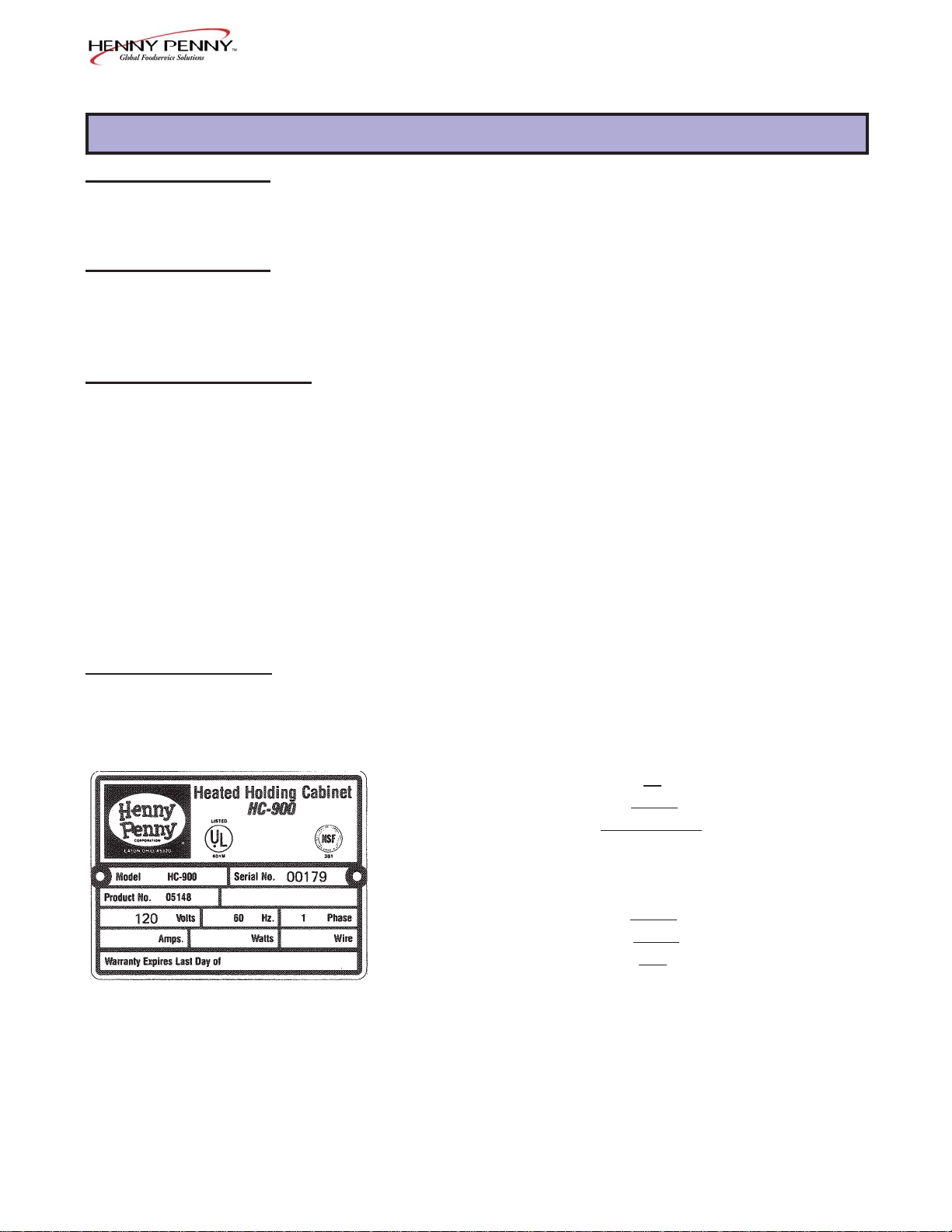
2. From the data plate (SAMPLE)
Product Number _________05148_______________
Serial Number ___________00179_______________
Voltage _________________120________________
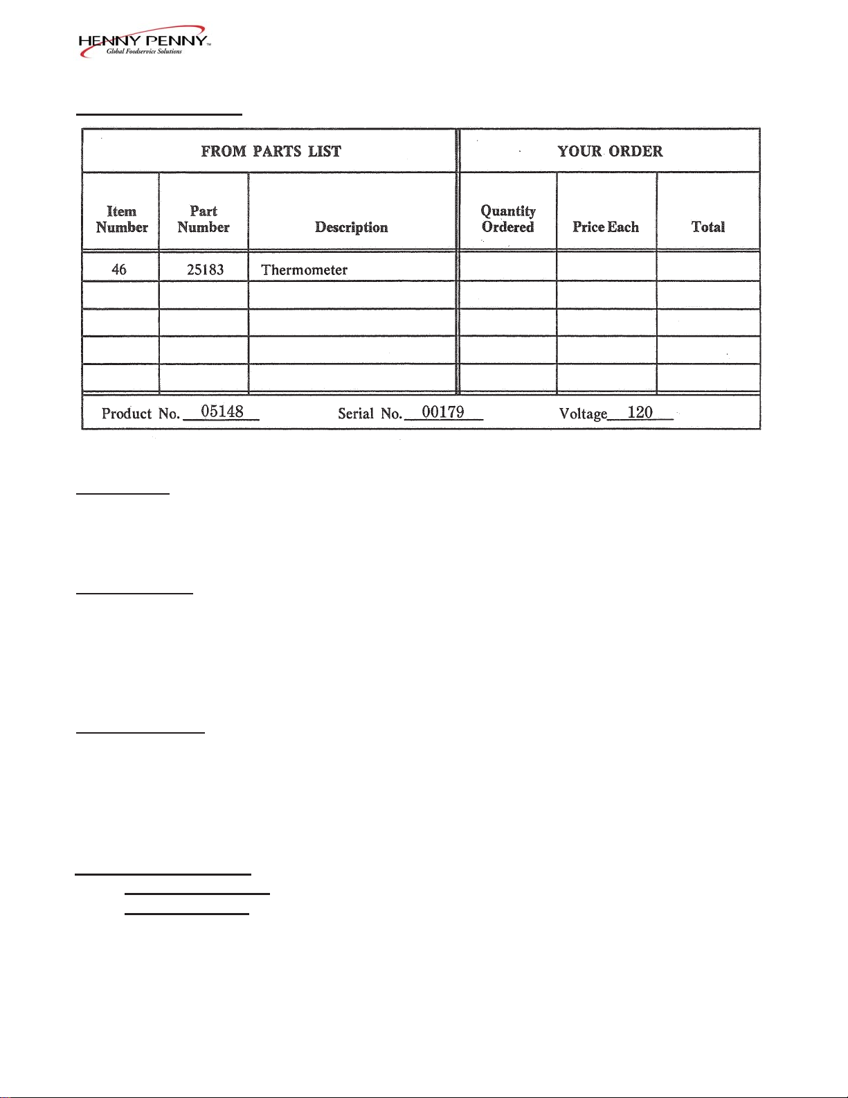
3. The following table has been provided as a sample format for
you to use in preparing your spare parts orders. By providing
all the entries, your distributor will be able to insure the correct
parts will be sent to you. Also, by prepayment your order will
be expedited.
1287 6-1
Page 2
6-4. HOW TO ORDER
Model HC-900
6-5. PRICES Y our distributor has a priced parts list and will be glad to
inform you of the cost of your parts order .
6-6. DELIVERY Commonly replaced items are stocked by your distributor and
will be sent out when your order is received. Other parts will be
ordered by your distributor from Henny Penny Corporation.
Normally , these will be sent to your distributor within three
working days.
6-7. WARRANTY All replacement parts (except lamps and fuses) are warranted
for 90 days against manufacturing defects and workmanship. If
damage occurs during shipping, notify the sender and the carrier
at once so that a claim may be properly filed. Refer to warranty
in the front of this section for other rights and limitations.
6-8. RECOMMENDED
SPARE P ARTS FOR
DISTRIBUTORS
Recommended replacement parts, stocked by your distributor,
are indicated with
√√
√ in the parts lists. Please use care when
√√
ordering recommended parts, because all voltages and variations are marked. Distributors should order parts based upon
common voltages and equipment sold in their territory .
6-2 206
Page 3
Model HC-900
HC-900 CONTROL MODULE
(with Adjustable Humidity)
No. Part No. Description Qty.
1 25704 Panel - Access 1
2 SC01-053 Screw #8-32 x 1/2 PH RHD 4
3 28719 Panel - Rear S/A 1
4 EC04-002 Terminal Flag #10-10-12 Ga. 1
5 MS01-212 Cable - 12/3 90C 600Y 8 ft.
6 25765 Plug 125V 20 Amp 1
7 SC01-010 Screw #6-32 x 1/2 PH PHP 2
√√
√ 8 EF02-007 Fuse - 15 Amp 1
√√
9 EF02-042 Connector - Cable 3/4 1
10 SC02-023 Screw 8#-B x 3/8 PH THP 15
11 NS02-001 Nut #10-32 Hex Keps 1
√√
√ 12 EF02-006 Fuse Holder 1
√√
13 NS02-005 Nut #6-32 Hex Keps 2
14 EC01-010 Wire Nut 12-18 Ga. 2
15 25602 Top 1
16 25628 Insulation - Cover 1
17 SC02-016 Screw #8 A B x 1/2 PH PHD 18
18 25620 Seal 2
19 25624 Seal 2
√√
√ 20 28723 Heater 240V, 1750W (120V, 440W) 1
√√
21 25619 Gasket - Blower Outlet 2
22 25618 Gasket Retainer 2
23 SC02-012 Screw #10 - ABX 3/8 PH PHD 12
24 SC01-055 Screw #10-32 x 3/4 Hex HD 2
25 EF02-031 Clamp 1/4 ID x 3/8 W 2
26 EF02-033 Clamp 7/16 x 3/8 W 2
27 25627 Gasket 2
28 28707 Box - Blower 2
28 25616 Rear Box - Blower 2
29 NS02-001 Nut #10 x 32 Hex Keps 2
30 25698 Gasket - Blower Plate 4
31 25622 Inlet - Flange 2
32 25623 Housing - Blower 2
33 25621 Wheel - Blower 2
34 SC01-090 Screw #6-32 x 5/16 SL RH 8
35 LW02-010 Lockwasher - Internal #65 8
36 25632 Plate - Blower 2
37 25767 Spacer - Motor 8
√√
√ 38 25751 Motor - Blower 120V 1
√√
39 SC01-091 Screw #6-32 x 1 3/4 SL 8
40 25768 Spacer - Cooling Fan 2
√√
√ 41 25706 Fan - Cooling 3 1/2” 2
√√
√√
√ 42 25738 He a te r 120V/750W 2
√√
√√
√ 43 18201 Hi Limit Thermostat 2
√√
√√
√ 44 22198 Power Switch 1
√√
√√
√ recommended parts
√√
206 6-3
Page 4

Model HC-900
HC-900 CONTROL MODULE
(with Adjustable Humidity)
No. Part No. Description Qty.
√√
√ 45 16624 Indicator Light 2
√√
√√
√ 46 25183 Thermometer 1
√√
47 25863 Knob - Thermostat-Optional 1
48 SC02-030 Screw #8- B x 3/8 PH 4
49 25986 Label - Control Panel with Power + Warm 1
49 61469 Label - Control Panel - Wendy’s 1
50 27006 Panel - Control S/A 1
51 25263 Extension - Thermnostat Shaft - Optional 1
52 25241 Bracket - Thermostat Mount 1
√√
√
53 14209 Thermostat 1
√√
54 25734 Insulation 5 x 7 x 1 2
55 25733 Insulation 6 x 6 _ x 1 4
56 25735 Insulation 5 x 10 _ x 1 2
57 PL01-001 Plug Button _ 1
58 FP05-002 Union Bulkhead 1
59 NS01-017 Nut 1
60 28722 Fitting - Bulkhead 1
√√
√ 61 28856 Float Switch 1
√√
62 28687 Guard - Float 1
63 SC02-014 Screw #8-AB x 3/8 PH THD S. *
64 28703 Cradle 1
65 25644 Spacer 4
66 28689 Cover - Heater 1
67 MS01-129 Tubing 1/4 OD .030 WALL 2 ft.
√√
√ 68 25147 Valve Solenoid 1
√√
√√
√ 69 22045 Infinite Switch 1
√√
70 FP01-012 Nipple - Reducing 1
71 NS02-005 Nut Hex Keps #6-32 2
72 28697 Bracket - Infinite Switch 1
73 PL01-015 Plug Button - 13/16 1
74 FP01-013 Bulkhead Adapter 1
75 FP05-007 Elbow (1/4 pipe to 1-4 pipe) 1
76 FP02-009 Nipple - Close (1/4) 1
√√
√ 77 25208 Water Strainer 1
√√
78 FP01-053 Fitting 3/8 ID Tubing 1/4 NPT 1
79 MS01-263 Clamp 1
80 28731 Hose 8 ft.
81 EF02-043 Grommet 1
82 28699 Bottom - False 1
√√
√ 83 25994 Timer - Delay 1
√√
√√
√ recommended parts
√√
6-4 206
Page 5

Model HC-900
1287 6-5
Page 6

Model HC-900
HC-900 CABINET ASSEMBL Y
(with Adjustable Humidity)
No. Part No. Description Qty.
1 28726 Control Module - 120 V - 1940 W 1
2 SC01-092 Screw #10-32 x 3 SL RHD 4
3 27049 Door Assembly (Optional 4 Door) 2
4 25702 Hinge Assembly 4
5 LW02-013 Lockwasher External #10 16
6 SC01-086 Screw #12-32 x 3/4 PH TH 8
7 SC01-074 Screw #10-32 x 1/2 PH TH 8
8 LW 01-002 Lockwasher Split 1/4” 8
9 SC01-039 Screw #1/4-20 x 1 Hex Head 8
10 27155 Caster 5” 4
1 1 27154 Caster 5” W/Brake 4
12 25715 Decorator Cover 2
13 SC01-075 Screw #10-32 x 3/4 PHT TH 12
14 25695 Washer 12
15 25644 Spacer 12
16 25687 Retainer 4
17 SC02-016 Screw #8-AB x 1/2 PH PHD 12
18 25689 Retainer 4
19 28710 Cabinet Assembly - Less Module 1
20 NS01-008 Nut #8-32 Hex S 5
21 LW02-006 Lockwasher - Internal #8 S 5
22 SC01-053 Screw #8-32 x 1/2 PH RHD 5
√√
√ 23 25643 Door Gasket 2
√√
24 28714 Water Box Weld Assembly 1
25 SC01-038 Screw #10-24 x 3/8 PH THD S 2
26 LW02-005 Lockwasher #10 Internal 2
27 25712 Cock Drain 1
28 28711 Handle Protector 1
29 28712 Handle - Plastic 1
30 28729 Air Duct Assembly - Upper 2
31 28728 Air Duct Assembly - Lower 2
32 NS03-024 Nut #8-32 B PL Acorn *
33 LW02-006 Lockwasher Internal #8 S *
34 25696 Hanger 8
35 SC01-076 Screw #8-32 x 1/4 PH THD S *
36 25937 Latch Assembly
37 SC01-099 Screw
38 28691 Slide - Tray 8
39 25984 Leg Assembly - Optional (not shown) 4
√√
√ recommended parts
√√
6-6 206
Page 7

Model HC-900
1287 6-7
 Loading...