

Page 1
OPERATOR’S
MANUAL
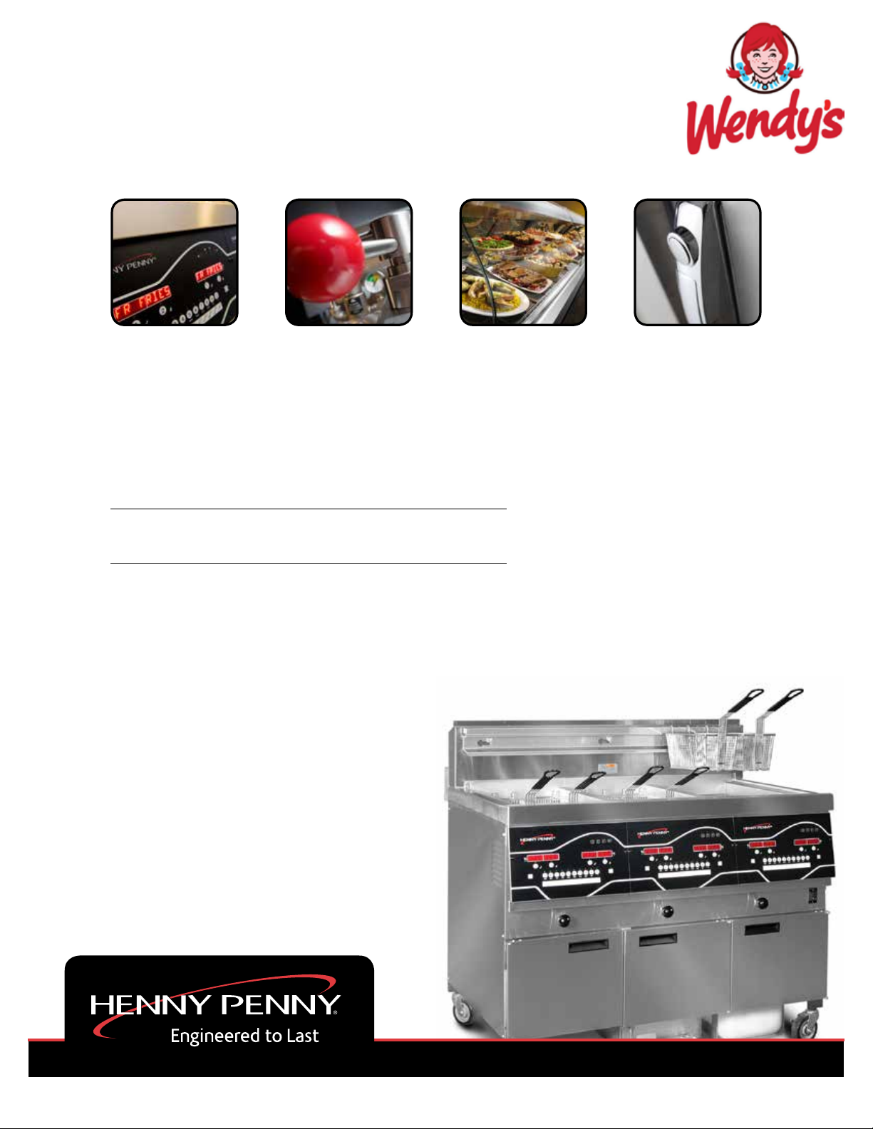
WENDY’S EVOLUTION ELITE™ (Gas)
REDUCED OIL CAPACITY OPEN FRYER
MODEL
EEG-253
EEG-254
REGISTER WARRANTY ONLINE AT WWW.HENNYPENNY.COM
Page 2

Page 3
This manual should be retained in a convenient location for future reference.
A wiring diagram for this appliance is located on the inside of the door.
Post in a prominent location, instructions to be followed in event user smells gas. This information shall
be obtained by consulting the local gas supplier.
Do not obstruct the ow of combustion and ventilation air. Adequate clearance must be left all around
appliance for sufcient air to the combustion chamber.
The Model EEG-10X open fryer is equipped with a continuous pilot. But the open fryer cannot be
operated without electric power, and no attempt should be made to operate the fryer during a power
outage. The unit will automatically return to normal operation when power is restored.
To avoid a re, keep appliance area free and clear from combustibles.
Improper installation, adjustment, alteration, service, or maintenance can
cause property damage, injury, or death. Read the installation, operating,
and maintenance instructions thoroughly before installing or servicing this
equipment.
DO NOT STORE OR USE GASOLINE OR OTHER FLAMMABLE
VAPORS AND LIQUIDS IN THE VICINITY OF THIS OR ANY OTHER
APPLIANCE. FIRE OR EXPLOSION COULD RESULT.
Page 4

Technical Data for CE/AGA Marked Products
Nominal Heat Input: Natural (I2H) = 19,8, kW (67,560 Btu/h)
(Net) Natural (I
Natural (I2E+) = 19.8 kW (67,560 Btu/h)
Natural (I
Natural (I
Liquid Propane (I3P) = 19,8, kW (67,560 Btu/h)
Nominal Heat Input: Natural (I2H) = 21,98 kW (75,000 Btu/h) (79.13 MJ/h)
(Gross) Natural (I2E) = 21,98 kW (75,000 Btu/h)
Natural (I
Natural (I2L) = 21,98 kW (75,000 Btu/h)
Natural (I
Liquid Propane (I3P) = 21,98 kW (75,000 Btu/h) (79.13 MJ/h)
) = 19.8 kW (67,560 Btu/h)
2E
) = 19.8 kW (67,560 Btu/h)
2L
) = 19.8 kW (67,560 Btu/h)
2HS
+) = 21,98 kW (75,000 Btu/h)
2E
) = 21,98 kW (75,000 Btu/h)
2HS
Supply Pressure: Natural (I
Natural (I
) = 20 mbar (2.0 kPa)
2H
) = 20 mbar
2E
Natural (I2E+) = 20/25 mbar
Natural (I2L) = 25 mbar
Natural (I
) = 25 mbar
2HS
Liquid Propane (I3P) = 30/37/50 mbar (3.0/3.7/5.0 kPa)
Test Point Pressure: Natural (I
Natural (I
Natural (I
Natural (I
Natural (I
) = 8.7 mbar (.87 kPa)
2H
) = 8,7 mbar
2E
+) = N/A
2E
) = 8.7 mbar
2L
) = 8.7 mbar
2HS
Liquid Propane (I3P) = 25 mbar (2.5 kPa)
Injector Size: Natural (I2H) = 2.08 mm
Natural (I2E) = 2.08 mm
Natural (I2E+) = 1.70 mm
Natural (I
Natural (I
Liquid Propane (I
) = 2.30 mm
2L
) = 2.30 mm
2HS
3P
) = 1.30 mm
This appliance must be installed in accordance with the manufacturer’s instructions and the regulations
in force and only used in a suitable ventilated location. Read the instructions fully before installing or
using the appliance.
Noise generated from this equipment is less than 70 dB(A)
Page 5

TABLE OF CONTENTS
INTRODUCTION ...............................................................................................................1
1-1 Safety ................................................................................................................... 1
1-2 Introduction .........................................................................................................3
1-3 Features ................................................................................................................3
1-4 Proper Care .......................................................................................................... 3
1-5 Assistance ............................................................................................................ 3
INSTALLATION .................................................................................................................5
2-1 Introduction .........................................................................................................5
2-2 Unpacking ............................................................................................................5
2-3 Selecting the Fryer Location................................................................................6
2-4 Leveling the Fryer ...............................................................................................6
2-5 Ventilation of Fryer .............................................................................................. 6
2-6 Gas Supply ...........................................................................................................7
2-7 Gas Leak Test ....................................................................................................10
2-8 Gas Pressure Regulator Setting .........................................................................10
2-9 Electrical Requirements .....................................................................................10
2-10 Motor Bearings .................................................................................................. 11
2-11 Lighting and Shutdown of the Burners.............................................................. 11
2-12 Testing the Fryer ................................................................................................ 11
2-13 Dimensions ........................................................................................................ 12
OPERATION .....................................................................................................................15
3-1 Operating Components ...................................................................................... 15
3-2 Set-Up Mode......................................................................................................19
3-3 Filling or Adding Oil .........................................................................................20
3-4 Morning Start-Up Procedures ............................................................................21
3-5 Basic Operation .................................................................................................22
3-6 Idle Mode ...........................................................................................................22
3-7 Oil Guardian™ (Auto Top-Off) ......................................................................... 23
3-8 Selecting a Product with a Different Setpoint ...................................................23
3-9 Replacing the BIB .............................................................................................23
3-10 Filter - Smart Touch ........................................................................................... 24
3-11 Auto Daily Filtering........................................................................................... 26
3-12 Discarding Oil from Vat Using Optional Discard Shuttle ................................. 28
3-13 Discarding Oil from Vat Using Optional Bulk Oil Dispose System .................29
3-14 Discarding Oil Using Optional Oil Discard Shuttle - ODS-400 .......................30
3-15 Discarding Oil Using Optional Oil Discard Shuttle - ODS-450 .......................33
3-16 Changing the Filter Pad ..................................................................................... 36
3-17 Removing and Cleaning Basket Rest ................................................................ 39
3-18 Clean-Out Mode - Smart Touch ........................................................................39
3-19 Coldsoak Procedure ........................................................................................... 42
3-20 Check/Replace Filter Drain Pan O-Rings .......................................................... 43
3-21 Info Button Stats ................................................................................................ 44
3-22 Filter Button Stats .............................................................................................. 44
3-23 Preventive Maintenance Schedule ..................................................................... 45
3-24 Clean Blower & Vents ....................................................................................... 46
INFORMATION MODE ...................................................................................................47
4-1 Information Mode Details .................................................................................47
iMarch 2017
Page 6

PRODUCT PROGRAM MODE .......................................................................................53
5-1 Modifying Product Settings ............................................................................... 53
LEVEL 2 PROGRAMMING .............................................................................................57
6-1 Special Program Mode ......................................................................................59
6-2 Do Not Disturb ..................................................................................................65
6-3 Clock Set............................................................................................................66
6-4 Data Logging, Heat Control, Tech, Stat, and Filter Control Mode ...................66
TROUBLESHOOTING .....................................................................................................67
7-1 Troubleshooting Guide ......................................................................................67
7-2 Error Codes ........................................................................................................ 69
iiMarch 2017
Page 7
SECTION 1: INTRODUCTION
1-1
SAFETY
The instructions in this manual have been prepared to aid you
in learning the proper procedures for your equipment. Where
information is of particular importance or is safety related, the
words NOTICE, CAUTION, or WARNING are used. Their usage
is described below.
If a problem occurs during the rst operation of a new unit,
recheck the Installation Section of the Operator’s Manual.
Before troubleshooting, always recheck the Operation
Section of the Operator’s Manual.
Where information is of particular importance or is safety related,
the words DANGER, WARNING, CAUTION, or NOTICE are
used. Their usage is described as follows:
SAFETY ALERT SYMBOL is used with DANGER,
WARNING or CAUTION which indicates a personal
injury type hazard.
NOTICE is used to highlight especially important
information.
CAUTION used without the safety alert symbol
indicates a potentially hazardous situation which, if
not avoided, may result in property damage.
CAUTION used with the safety alert symbol indicates
a potentially hazardous situation which, if not
avoided, could result in minor or moderate injury.
WARNING indicates a potentially hazardous
situation which, if not avoided, could result in death
or serious injury.
DANGER INDICATES AN IMMINENTLY
HAZARDOUS SITUATION WHICH, IF NOT
AVOIDED, WILL RESULT IN DEATH OR
SERIOUS INJURY.
1March 2017
Page 8
1-1.
SAFETY
(CONT.)
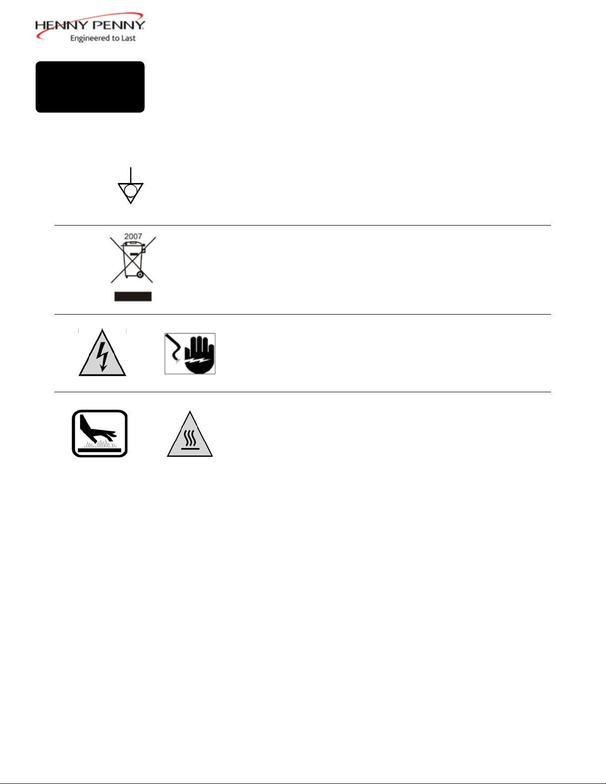
Equipotential Ground Symbol
Waste Electrical and Electronic Equipment (WEEE) Symbol
OR
OR
Shock Hazard Symbols
Hot Surface Symbols
2Aug. 2013
Page 9
1-2.
INTRODUCTION
The Henny Penny open fryer is a basic unit of food processing equipment
designed to cook foods better and easier. The micro computer-based
design helps make this possible. This unit is used only in institutional and
commercial food service operations, and operated by qualied personnel.
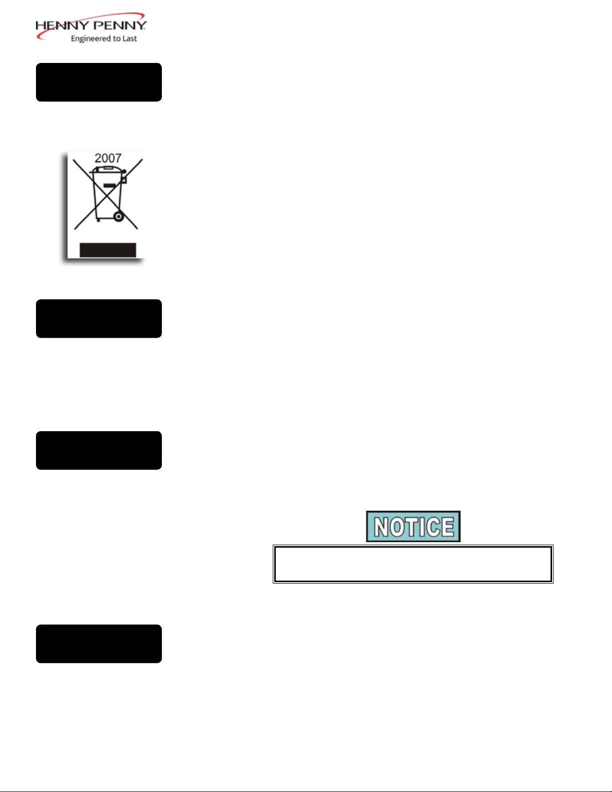
• As of August 16, 2005, the Waste Electrical and Electronic
Equipment directive went into effect for the European Union. Our
products have been evaluated to the WEEE directive. We have
also reviewed our products to determine if they comply with the
Restriction of Hazardous Substances directive (RoHS) and have
redesigned our products as needed in order to comply. To continue
compliance with these directives, this unit must not be disposed as
unsorted municipal waste. For proper disposal, please contact your
nearest Henny Penny distributor.
1-3.
FEATURES
1-4.
PROPER CARE
• Easily cleaned
• Uses 40% less oil
• Full vat or split vat
• Computer control
• Stainless steel construction
• Automatic oil top off
• Self-diagnostic system built into controls
• Built in lter with automatic ltration
• Propane or natural gas; 75,000 BTU/vat (21.97 kw)
As in any unit of food service equipment, the Henny Penny
open fryer does require care and maintenance. Requirements for the
maintenance and cleaning are contained in this manual and must become
a regular part of the operation of the unit at all times.
Contact a qualied service technician in case of major maintenance
or repairs to the unit.
1-5.
ASSISTANCE
Should you require outside assistance, call your local independent
distributor in your area, or call Henny Penny Corp. at 1-800-417-8405 or
1-937-456-8405.
3Aug. 2013
Page 10

Page 11
SECTION 2: INSTALLATION
2-1.
INTRODUCTION
2-2.
UNPACKING
This section provides the installation and unpacking instructions for the
®
Henny Penny Evolution Elite
Installation of this unit should be performed only by a qualied service
Do not puncture the fryer with any objects such as drills or screws as
component damage or electrical shock could result.
Any shipping damage should be noted in the presence of the delivery agent
and signed prior to his or her departure.
fryer.
technician.
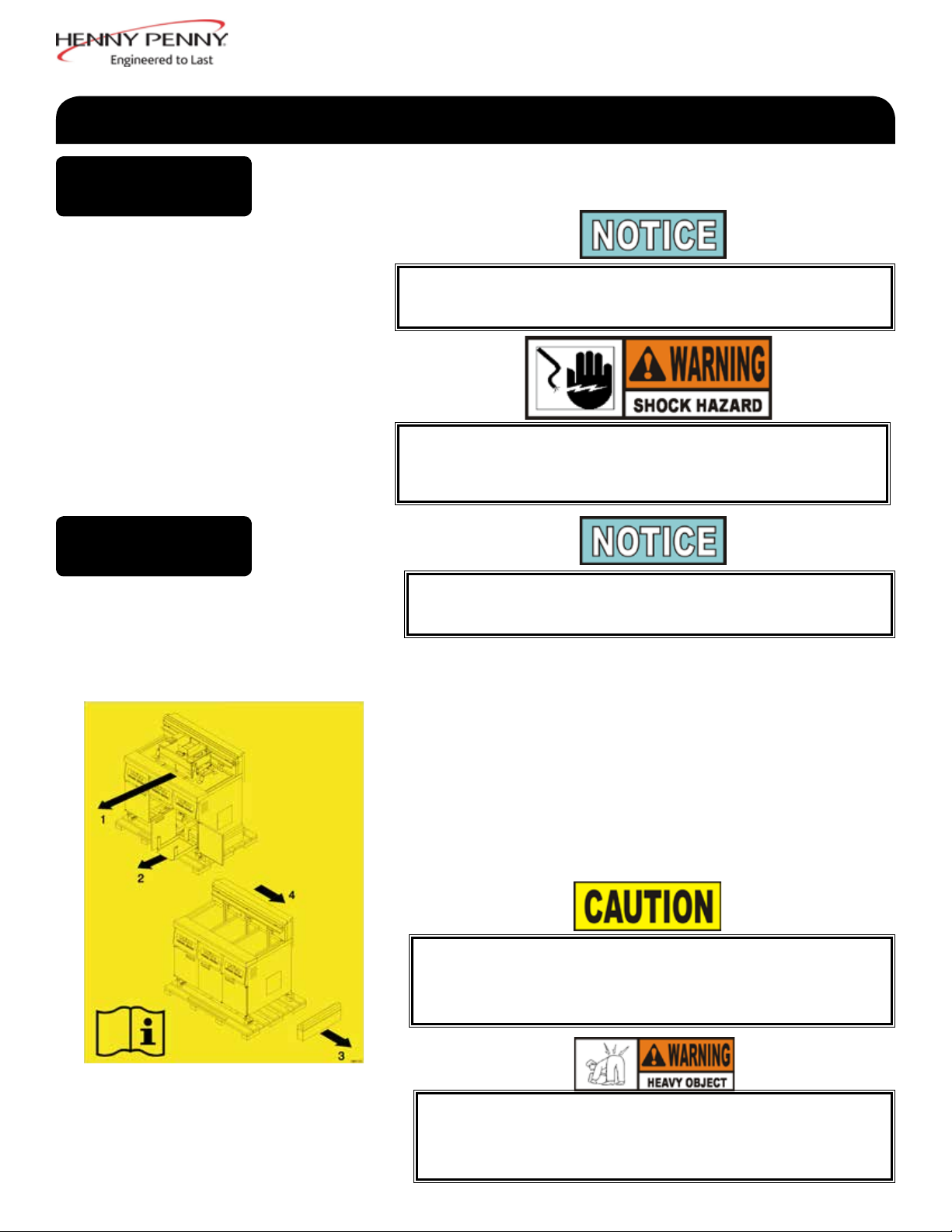
1. Cut and remove the metal bands from the carton.
2. Remove carton lid and lift the main carton off the fryer.
3. Remove corner packing supports (4).
4. Cut the stretch lm from around the carrier/rack box and remove it
from the top of the fryer lid.
5. Cut and remove the metal bands holding the fryer to the pallet, and
remove fryer from pallet.
Remove lter drain pan and BIB shelf from fryer before removing fryer from
pallet or damage to the unit could result. Figure 1.
Take care when moving the fryer to prevent personal injury. The fryer
weighs approximately 600 lbs. (272 kg) to 800 lbs. (363 kg).
5Aug. 2013
Page 12
2-3.
SELECTING THE
FRYER LOCATION
The proper location of the fryer is very important for operation, speed,
and convenience. The location of the open fryer should allow clearances
for servicing and proper operation. Choose a location which will provide
easy loading and unloading without interfering with the nal assembly
of food orders. Operators have found that frying from raw to nish, and
holding the product in warmers provides fast continuous service. Keep
in mind, the best efciency will be obtained by a straight line operation,
i.e. raw in one side and nished out the other side. Order assembly can
be moved away with only a slight loss of efciency.
To avoid re, install the open fryer with minimum clearance from all
combustible materials, 2 inches (5.08 cm) from the side and 4 inches
(10.16 cm) from the back. Minimum clearance from all non-combustible
materials, 0 inches (0.00 cm) from the side and 0 inches (0.00 cm) from the
back. If installed properly, the open fryer is designed for operation on non-
combustible oors only
Do not spray aerosols in the vicinity of this appliance while it is in operation.
2-4.
LEVELING THE
FRYER
2-5.
VENTILATION OF
FRYER
To prevent severe burns from splashing hot oil, position and install
fryer to prevent tipping or movement. Restraining ties may be used for
stabilization.
For proper operation, the open fryer should be level from side-to-side and
front to back. Using a level placed on the at areas around the vat collar,
on the middle well, and then adjust the casters until the unit is level.
The fryer should be located with provision for venting into an adequate
exhaust hood or ventilation system. This is essential to permit efcient
removal of the steam exhaust and frying odors. Special precaution must
be taken in designing an exhaust canopy to avoid interference with the
operation of the fryer. We recommend you consult a local ventilation or
heating company to help in designing an adequate system.
Ventilation must conform to local, state, and national codes.
Consult your local fire department or building authorities.
6Aug. 2013
Page 13
2-6.
GAS SUPPLY
When installing the gas open fryer, do not attach an extension
to the gas ue exhaust stack. This may impair proper
operation of the burner, causing malfunctions and possible
negative back draft.
The gas open fryer is factory available for either natural or propane gas.
Check the data plate inside the left front door of the cabinet to determine
the proper gas supply requirements. The minimum supply for natural
gas is 7 inches water column (1.7 kPa) (17.0 mbar), and 10 inches water
column (2.49 kPa) (24.9 mbar) for propane.
Do not attempt to use any gas other than that specied on the
data plate. Incorrect gas supply could cause a re or explosion
resulting in severe injuries and/or property damage.
Please refer below for the recommended hookup of the fryer to main gas
line supply.
To avoid possible serious personal injury:
• Installation must conform with local, state,
and national
codes, the American National Standard
Z223.1/NFPA 54 -(the latest edition) National
Fuel Gas Code, and the local municipal
building codes. In Canada, the Natural
Gas and Propane Installation Code is CSA
B149.1 & Installation Codes - Gas Burning
Appliances and local codes. In Australia, in
accordance with Australian Gas Authority
rules AS5601.1/2-2010.
• The fryer and its manual shutoff valve must
disconnected from the gas supply piping
be
system during any pressure testing of that
system at test pressures in excess of 1/2 PSIG
(3.45 kPa) (34.5 mbar).
• The fryer must be isolated from the gas
supply piping system by closing its individual
manual shutoff valve during any pressure
testing of the gas supply piping
system at test pressures equal to or less than
1/2 PSIG (3.45 kPa) (34.5mbar).
• A standard one inch (2.54 cm), black steel
pipe and
malleable ttings should be used for gas
service connections for 3 & 4 well open
fryers, and 3/4 inch (1.91 cm) for 2 wells.
• Do not use cast iron ttings.
• Although one inch (2.54 cm) size pipe is rec-
ommended for 3 & 4 wells and 3/4 inch (1.91
cm) for 2 wells, piping should be of adequate
size and installed to provide a supply of gas
sufcient to meet the maximum demand
without undue loss of pressure between the
meter and the open fryer. The pressure loss
in the piping system should not exceed 0.3 in.
water column (0.747 mbar).
7Aug. 2013
Page 14
2-6.
GAS SUPPLY
(CONT.)
Provisions should be made for moving the open fryer for cleaning and
servicing. This may be accomplished by:
1. Installing a manual gas shutoff valve and a disconnect or union.
2. Installing a heavy-duty design CSA certied connector. In order to
be able to service this appliance, which is provided with casters,
a connector complying with ANSI Z21.69-CAN 6.16 or CAN
1-6.10m88 and a quick-disconnect device, complying with ANSI
Z21.41or CAN 1-6.9m70, must be installed. It must also be installed
with restraining means to guard against transmission of strain to the
connector as specied in the appliance manufacturer’s instructions.
3. See the illustration on the following page for the proper connection
of exible gas line and cable restraint.
The cable restraint limits the distance the open fryer can be pulled from
the wall. For cleaning and servicing the unit, the cable must be unsnapped
from the open fryer and the exible gas line disconnected. This allows better
access to all sides of the open fryer. The gas line and cable restraint must be
reconnected once the cleaning or servicing is complete.
8Aug. 2013
Page 15
2-6.
GAS SUPPLY
(CONT.)
MINIMUM PULL of equipment
away from wall permissible
for accessibility to Quick
Disconnect Device
DISCONNECT
BEFORE
MAXIMUM PULL
GAS PIPING
AVOID SHARP BENDS AND KINKS when
pulling equipment away from wall. (Maximum
pull will kink ends, even if installed properly,
and reduce Connector life.)
QUICK DISCONNECT
DEVICE still attached
while extended at
maximum pull
STRESS
POINTS
STRESS
POINTS
CABLE RESTRAINT
Please refer to the illustration below
when installing cable restraint on all
moveable gas fryers.
MINIMUM PULL FOR
ACCESSIBILITY
ONLY
Couplings and hose should
be installed in the same
plane as shown at left. DO
NOT OFFSET
COUPLINGS -- this causes
torsional twisting and
undue strain causing
premature failure
This is the correct way to
install metal hose vor
vertical traverse. Note the
single, natural loop.
Allowing a sharp bend, as
shown at right, strains and
twists the metal hose to a
point of early failure at the
coupling
Maintain the minimum or
larger bending diameter
between the couplings for
longest life.
Closing in the diameter at
the coupling, as shown at
right, creates double bends
causing work work fatigue
failure of the fittings.
In all installations where
“self-draining” is not
necessary, connect metal
hose in a vertical loop.
DO NOT CONNECT
METAL HOSE �
HORIZONTALLY...unless
“self-draining” is necessary,
then use support on lower
plane as shown at left.
MAXIMUM PULL NOT
ADVISED WHILE
CONNECTED
I-bolt is to be secured to the building
using acceptable building contruction
practices.
DRY WALL CONSTRUCTION
Secure I-bolt to a building stud DO
NOT attach to dry wall only. Also,
locate the I-bolt at teh same height as
the gas service. Preferred installation
is approximately six inches to either
side of service. Cable restraint must
be at least six inches shorter than
flexible gas line.
Utilize elbows when necesary to avoid
sharp kinks or excessive bending. For
ease of movement, install with a
“lazy” loop. gas appliance must be
disconnected prior to maximum
movement. (Minimum movement is
permissible for hose disconnection).
12160004
9Dec. 2016
Page 16
2-7.
GAS LEAK TEST
2-8.
GAS PRESSURE
REGULATOR
SETTING
Prior to turning the gas supply on, be sure the gas valve knob on the gas
control valve is in the off position.
Upon initial installation, and after moving the unit, the piping and ttings
should be checked for gas leaks. A simple checking method is to turn on
the gas and brush all connections with a soap solution. If bubbles occur, it
indicates escaping gas. In this event, the piping connection must be redone.
To avoid re or explosion, never use a lighted match or open ame to
test for gas leaks. Ignited gas could result in severe personal injury and/
or property damage.
The gas pressure regulator on the gas control valve is factory set as follows:
• Natural: 3.5 inches water column (0.87 kPa) (8.72 mbar).
• Propane 10.0 inches water column (2.49 kPa) (24.9 mbar).
2-9.
ELECTRICAL
REQUIREMENTS
The gas pressure regulator has been set by Henny Penny and is not to be
adjusted by the user.
•
120 V, 50/60 Hz, 1 PH, 12 A
• 230 V, 50 Hz, 1 PH, 7 A
The 120 volt gas fryer is factory equipped with a grounded (earthed)
cord and plug for your protection against shock, and should be plugged
into a three-prong grounded (earthed) receptacle. Do not cut or remove
grounding (earthing) prong. Any 230 volt plug used on the 230 volt unit
must conform to all local, state, and national codes.
To avoid electrical shock, this appliance must be equipped with an
external circuit breaker which incorporates a 3mm disconnection in all
ungrounded (unearthed) conductors. The main power switch on this
appliance does not disconnect all line conductors.
10Aug. 2013
Page 17
2-9.
ELECTRICAL
REQUIREMENTS
(CONT.)
To avoid electrical shock, do not disconnect the ground
(earth) plug. This fryer must be adequately and safely
grounded (earthed). Refer to local electrical codes for
correct grounding (earthing) procedures or in absence
of local codes, with The National Electrical Code, ANSI/
NFPA No. 70-(the current edition). In Canada, all electrical
connections are to be made in accordance with CSA C22.2,
Canadian Electrical Code Part 1, and/or local codes.
Disconnect power supply before a thorough cleaning or servicing the fryer.
2-10.
MOTOR BEARINGS
2-11.
LIGHTING AND
SHUTDOWN OF THE
BURNERS
The electric motor bearings are permanently lubricated. DO NOT
LUBRICATE.
Turn the power switch to the OFF position.
1.
2. Wait at least 5 minutes and then turn power switch to the ON position.
3. Press button on the controls (left or right).
4. The burner lights and operates in a Melt Cycle until the
shortening reaches a preset temperature.
5. Once the display shows a product selection or a double
dashes, press the desired product button.
The fryer is equipped with a ignition spark module which has a
set ignition safety time (TSA) of 90 seconds.
2-12.
TESTING THE
FRYER
To shutdown burner:
1. Press button on the controls (left or right).
2. Turn the power switch to the OFF position.
NOTE: This turns off all vats.
Each Henny Penny open fryer was completely checked and tested
prior to shipment. However, it is good practice to check the unit for
proper operation.
11Aug. 2013
Page 18
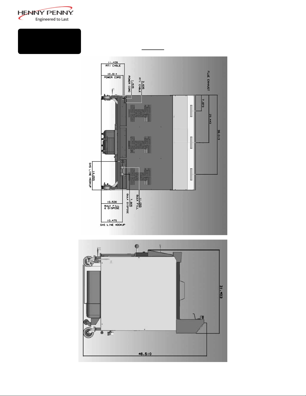
2-13.
DIMENSIONS
3-WELL
Back Side
Side dimensions are
the same for both 153
& 154 units.
12Aug. 2013
Page 19
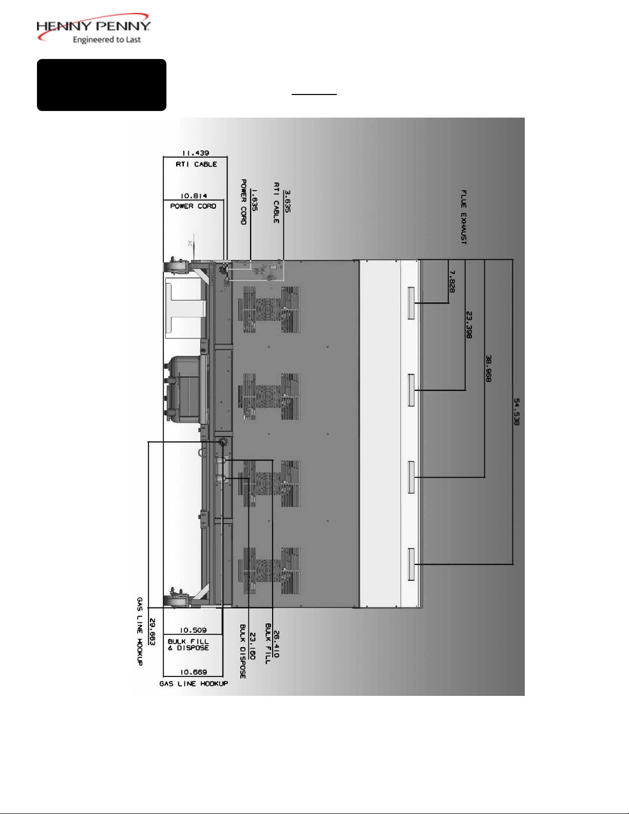
2-13.
DIMENSIONS
(CONT.)
4 WELL
Back
13Aug. 2013
Page 20

Page 21
SECTION 3: OPERATION
3-1.
OPERATING
COMPONENTS
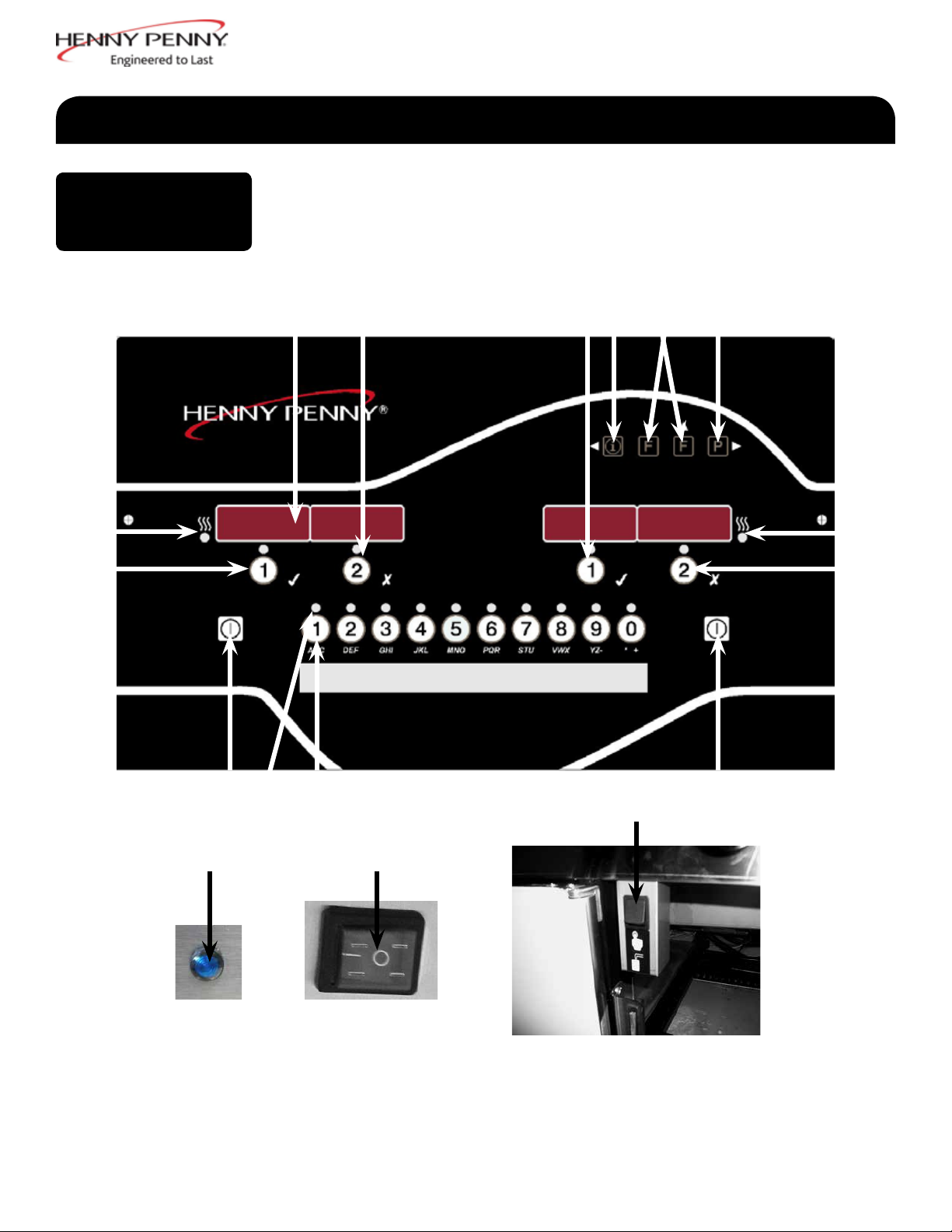
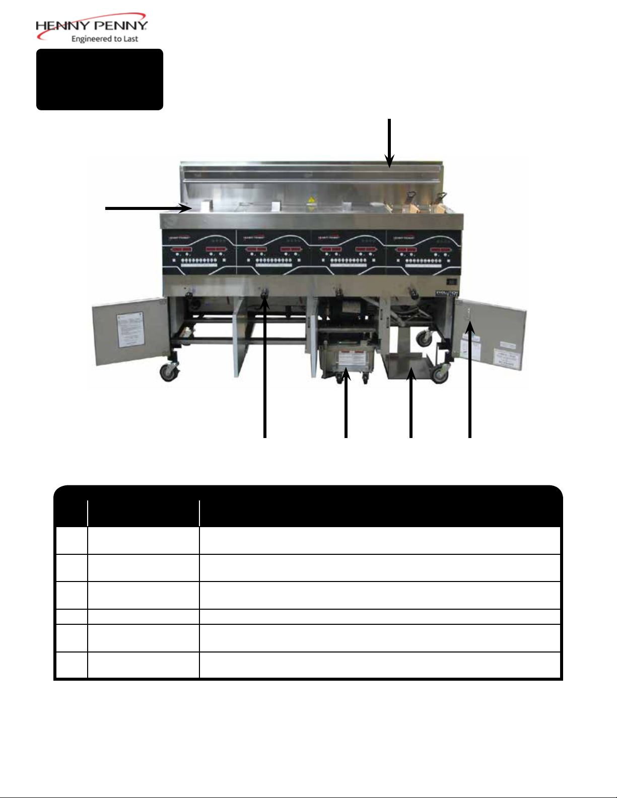
Figure 3-1
1
2
Refer to explanations on the next pages.
4
2 5 6 73
1
3
8
10 8
9
11 12
Figure 3-2
Figure 3-3
13
Figure 3-4
15Aug. 2013
Page 22
3-1.
OPERATING
COMPONENTS
(CONT.)
Fig.
Item
No.
3-1 1
3-1 2
3-1 3
3-1 4
3-1 5
Description Function
This LED lights when the control calls for heat for the left/ right vat, and the
burners ignite and heat the oil
During normal operation, press this button to start and stop cook cycles for the
left basket; press to change displayed product; also used for √ to indicate YES
or to conrm
During normal operation, press this button to start and stop cook cycles for the
left basket; press to change displayed product; also used for X to indicate NO
or cancel
Shows the product codes; shows the timer countdown during cook cycles;
shows the prompts during the lter modes; shows the selections in the Program
Digital Display
Mode; shows the temperature of the oil by pressing ; shows error codes
(also displays in several languages)
Press once to view actual oil temperature; press twice to view oil set-point
temperature; and press three times to view recovery information for each vat
o
from 250
F-300oF (121oC-149oC). Used in Programming Modes; used as ◄
button to back-up to a previous parameter in Program and Filter Modes.
3-1 6
3-1 7
3-1 8
3-1 9
3-1 10
Used to access the Filter Menu; also used for ▲ or ▼ buttons; press once to
view the number of cook cycles before next lter in Global Filter or the mode
or percentage of lter allowance in Mixed Filter; press twice to view the time
and date of the most recent lter on each vat; press three times to view the
number of hours of use of the lter pad presently in the drain pan.
Used to access the Program Modes; used as ► button to advance to the next
parameters in Program and Filter Modes; press to select 2nd languages and
volumes
Press to turn on and off the heat system for the left vat(s); on full vats either
button can be used
Each product button LED lights when that particular product has been
selected, or when it is compatible with cook temperature.
Press to select the desired product; press to place the letters under the button,
during naming a product in Program Mode
The can be used to start an Idle Mode if enabled in Special Program Mode
16Aug. 2013
Page 23
3-1.
OPERATING
COMPONENTS
(CONT.)
Fig.
Item
No.
3-2 11
3-3 12
3-4 13
Description Function
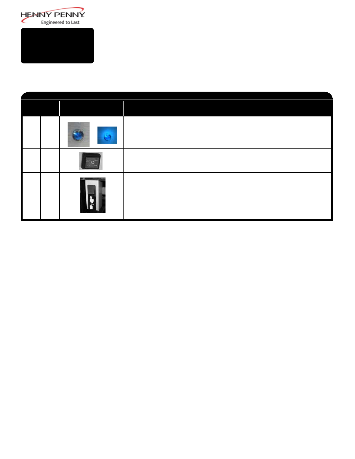
A Filter Beacon® is found beside each black drain knob; when lit blue, indicates
the oil should be ltered at this time; beacon ashes when the drain needs
opened or closed
When the power switch is turned to the ON position, power is supplied to the
controls and pumps
For fryers with a bulk oil supply, press this button to ll the BIB
17Aug. 2013
Page 24
3-1.
OPERATING
COMPONENTS
(CONT.)
4
3
2
Item
No.
1
2
3
4 Vat Covers Covers the vat when not in use
5
6 Quick Reference
Description Function
Filter Drain Pan Assy.
Drain Valve Knob
Basket Rest
BIB Support
Cards Hook
Oil is drained into this pan and then is pumped through lters to help
prolong the use of the oil
Pull-out on black knobs to open drain valve and oil drains from vat; Pushin to close drain valve and oil can be pumped into vat
The baskets hang on this when not in use, or to drain the product after a
cook cycle
Area that holds the Jug-in-a-Box; holds oil to be pumped into vats to topoff the oil level by the Oil Guardian™ process
Holds operational cards
1 5 6
18March 2014
Page 25

3-2.
SET-UP MODE
Upon initial start-up, the controls will ask to conrm the settings for
the fryer.
When main power switch is turned on, “OFF” shows in both
displays. Press on either side and *SETUP* *ENTER CODE*
shows in display. Press 1, 2, 3, and “LANGUAGE” shows on the
left display, “ENGLISH” on the right display.
Use ▲ or ▼ buttons to change the operation display to:
Greek “EΛΛHNIKA”, Russian “РУССКИИ”, Swedish
“SVENSKA”, German “DEUTSCHE”, Portuguese “PORTUG.”,
Spanish “ESPANOL”, or French “FRANCAIS”.
Press ► to continue with the other set-up items which include:
• TEMP FORMAT -
• TIME FORMAT - 12-HR or 24-HR
• ENTER TIME - Time of day (use product buttons to change)
• ENTER TIME - AM or PM
• DATE FORMAT - MM-DD-YY or DD-MM-YY
• ENTER DATE - Today’s date (use product buttons to change)
• DAYLIGHT SAVING TIME - 1.OFF; 2.US (2007 & after);
o
F or oC
3.EURO; 4.FSA (US before 2007)
• FRYER TYPE - ELEC or GAS
• VAT TYPE - FULL OR SPLIT
• AUTOLIFT ENABLED? - NO LIFT or YES LIFT
• BULK OIL SUPPLY - YES or NO
• BULK OIL DISPOSE? - YES or NO
• S/N - Shows serial number of the unit or can be recorded (THIS
SERIAL NUMBER SHOULD MATCH THE SERIAL
• NUMBER ON THE DATA PLATE, ON THE DOORS.)
• 2nd LANGUAGE - By setting a second language in the controls,
2 languages can now be easily chosen by pressing during
normal operation. One language shows in left display and
second language shows in right display. Pressing the √ button
under desired language, selects that language seen in displays.
• 2nd VOLUME - By setting a second volume in the controls,
2 volumes can now be easily chosen by pressing twice
during normal operation. One volume setting shows in left
display (NONE to 10; 10 being the loudest) and a second
volume shows in right display. To select volume, press √ button
under desired volume.
• SETUP COMPLETE - OFF is displayed and unit shuts down.
Unless otherwise indicated, use ▲ or ▼ to change settings.
Setup Mode can also be accessed by re-initializing the controls, in Special
Program Mode, in Level 2 programming (SP-3).
19Aug. 2013
Page 26

3-3.
FILLING OR ADDING
OIL
Figure 1
The oil level must always be above the burner tubes when the fryer
is heating and at the oil level indicators on the rear of the vat.
Failure to follow these instructions could result in a re and/or
damage to the fryer.
Solid oil is not recommended. Solid oil could cause clogging and
pump failures.
1. It is recommended that a high quality frying oil be used in the
open fryer. Some low grade oils have a high moisture content
and causes foaming and boiling over.
2. Oil Capacities:
Full-size vats = 15 quarts/30 lbs (14.2 liters/13.6 kg)
3. All vats have 2 level indicator lines inscribed on the rear wall of
the vat. The upper-most line shows the oil at the proper level when
heated. Figure 1.
3. Place basket support inside of vat and ll vat with cold oil to the
lower indicator. Figure 2.
Figure 2
Figure 3
Wear gloves to avoid severe burns when pouring hot oil into
vat. Oil and all metal parts that are in contact with the oil are
extremely hot; take care to avoid splashing.
Filling Vat from Bulk Supply (Must be equipped with optional
accessories & controls set to “YES” for “Bulk Oil Supply?” in SetUp Mode)
1. Turn the main power switch to the ON position.
2. Place basket support inside of vat. Figure 2.
3. Press and hold (on either side) until display shows*FILTER
MENU*, along with 1.EXPRESS FILTER?
4. Press and release ► button 6 times until display shows “7. FILL
FROM BULK”.
5. Press √ button and display shows “FILL VAT” and then “√=PUMP”
“X=DONE”. Press and hold √ button again to ll vat and display
shows “FILLING”.
6. Once oil is to the lower ll line, release √ button and display
returns to “FILL VAT” “√=PUMP” “X=DONE”. Press X button
twice to return to normal operation.
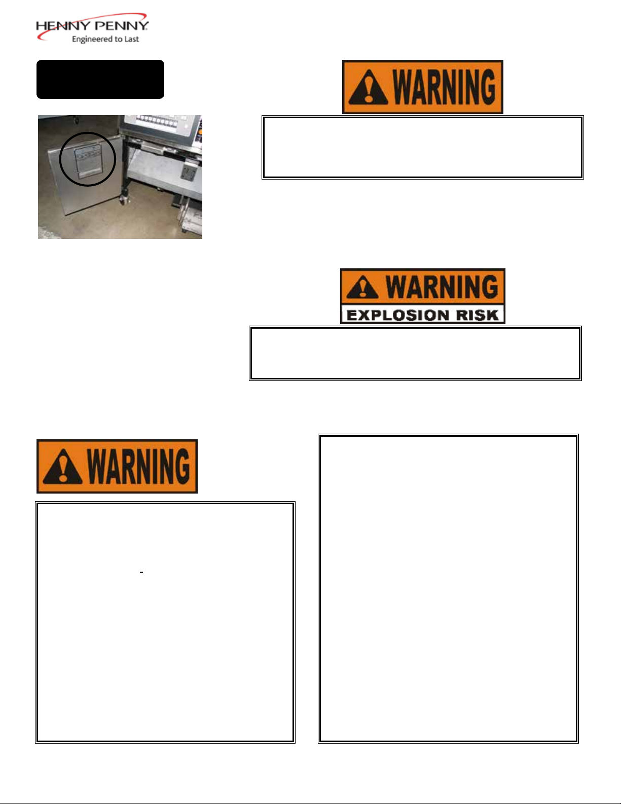
Press and hold the black button behind the right door to ll the BIB from
the Bulk Supply as needed. Figure 3.
20Aug. 2013
Page 27

3-4.
MORNING START-UP
PROCEDURES
Make sure basket support is in vat and vat is lled with oil
1.
to the proper level.
2. Move power switch to the ON position and then press to turn on heat
for the desired vat. If display shows “IS POT FILLED?” make sure
oil is at the proper level (see Section 3-2) and then press √ button for
“YES”.
3. Unit automatically goes into the Melt Cycle until the oil
temperature reaches 180°F (82°C) and then control automatically
exits the Melt Cycle.
The Melt Cycle may be bypassed, if desired, by pressing √ button or X button
and holding it for 5 seconds.
The control then shows “EXIT MELT” and “YES NO”. Press √
button for “YES” and vat heats continuously until the set-point
temperature is reached.
Do not leave fryer unattended and do not bypass the Melt Cycle
unless enough oil has melted to completely cover all of the burner
tubes. If the Melt Cycle is bypassed before the burner tubes are
covered, excessive smoking of oil, or a re will result.
DO NOT OVERLOAD, OR PLACE PRODUCT WITH
EXTREME MOISTURE CONTENT INTO THE BASKETS. 3
LBS. (1.4 KG.) IS THE MAXIMUM AMOUNT OF PRODUCT
PER FULL VAT AND 1-1/2 LBS. (.68 KG.) FOR THE SPLIT
VATS. FAILURE TO FOLLOW THESE INSTRUCTIONS
CAN RESULT IN OIL OVERFLOWING THE VAT WHICH
COULD CAUSE SERIOUS BURNS, PERSONAL INJURY,
FIRE AND/OR PROPERTY DAMAGE.
IF THE SHORTENING TEMPERATURE EXCEEDS
420°F (216°C), IMMEDIATELY SHUT OFF THE POWER
AT THE MAIN CIRCUIT BREAKER AND HAVE THE
FRYER REPAIRED. IF OIL TEMPERATURE EXCEEDS
ITS FLASHPOINT, FIRE WILL OCCUR, RESULTING IN
SEVERE BURNS AND/OR PROPERTY DAMAGE.
21Aug. 2013
Page 28

3-5.
BASIC OPERATION
The Evolution Elite fryer is available as non-auto-lift and auto-lift
models. The auto-lift controls, allow the baskets to be automatically
lowered into the shortening at the beginning of the cook cycle, and raised
from the shortening at the end of the cycle.
1. Once out of the Melt Cycle, LOW TEMP ashes until the setpoint
temperature has been reached. Once the setpoint temperature has
been reached, the product name now shows in the display, ex: FRY,
and product now can be placed in the oil.
2. Press a timer button or .
3. Display shows the name of the product cooking (ex: “FRY”) and the
timer counting down.
4. When cook cycle is complete, an alarm sounds and display shows
“DONE”.
5. Press the timer button under “DONE” to stop the alarm, and lift
basket from vat.
6. If a Quality Timer (hold timer) has been programmed, the hold time
starts automatically when the user presses the timer button to end the
cook cycle. While the quality timer counts down, the display shows
the three-digit product abbreviation followed by “Qn”,where “n” is
the number of minutes remaining. ex: “FRY” / “Q5” / “FRY” / “Q5”
/ “FRY” / “Q4”, etc.
At the end of the timer countdown, control beeps and the display shows
“QUAL” followed by the three-digit product name: “QUAL” / “FRY” /
“QUAL”/ “FRY”. Press the timer button to cancel the timer.
3-6.
IDLE MODE
To stop a cook cycle at any time, press and hold the timer
button or .
Once programmed, Idle Mode help saves on oil and utility costs by
lowering set-point of oil when vat is not being used. To activate Idle
Mode, press button, or can be programmed to activate automatically
after “X” minutes of inactivity on the vat.
The oil is maintained at a lower temperature until the button is
pressed, and then the oil is heated to cooking temperature. See Special
Program Modes SP-7, SP-7A, SP-7B, & SP-7C.
22Aug. 2013
Page 29

3-7.
OIL GUARDIAN™
(AUTO TOP-OFF)
3-8.
SELECTING A
PRODUCT WITH
A DIFFERENT
SETPOINT
During normal operation, the control automatically monitors vat oil
level. If the control senses oil level is too low, unit automatically pumps
oil from BIB into vat to keep oil at the proper level.
Manual Top-Off
If oil level is a little low, oil can be added to vat at any time from BIB
to raise oil level to the proper level by following steps below. This
procedure is NOT to be used to ll an empty vat.
1. Press and hold (either one-full vat) until display shows
“*FILTER MENU*” followed by “1.EXPRESS FILTER”.
2. Press ► 5 times until “6.FILL FROM BIB” shows in display.
3. Press √ button, “FILL VAT” “√=PUMP” “X=DONE” is displayed.
4. Press and hold √ button; display shows “FILLING” and oil is
pumped from the BIB to the vat.
5. Once vat is full, release √ button, “FILL VAT” “√=PUMP”
“X=DONE” displays. Press X button twice for normal operation.
When selecting a product, if “XXX XXX” shows in display, the setpoint
temperature is not correct for this product. To change the setpoint
temperature for the desired product:
1. Press product button, for ex: (FRY).
3-9.
REPLACING THE BIB
Figure 1
2. Display shows “XXX XXX”.
3. Press and hold a timer button or for 5 seconds and then
“FRY” shows in display.
4. Allow oil temperature to reach setpoint temperature before dropping
product.
1. Control displays “BIB IS LOW” and an alarm sounds.
2. Open right door, pull BIB from unit, pull cap from BIB top, discard
empty BIB, and replace with full one. Figure 1.
23Aug. 2013
Page 30

3-10.
FILTER - SMART TOUCH
This section describes how to run an automatic lter procedure using the
push-button feature.
1. During normal operation and after a certain number of cook cycles,
the blue light illuminates on the front of the fryer, and the control
periodically shows “FLTR NOW?” “YES NO”.
2. If ltering is desired, press √
button for YES and display shows
“SKIM VAT”, followed by “CONFIRM” “YES NO”.
3. Once the crumbs are skimmed off the top of the oil, press √ button
for YES and display shows shows “DRAINING” drain opens and
the oil drains from the vat. (If control suspects oil in drain pan
“CAUTION IS THERE OIL IN PAN? YES NO” may show in
display. Make sure drain pan is empty before proceeding.)
4. If ltering is NOT desired, press X button and the AIF (Automatic
Intermittent Filter) is canceled. The blue light goes out and the
controls return to normal operation. The controls will suggest
ltering after several more cook cycles.
If drain is clogged, see Section 3-22 to prevent damage to the fryer.
If display shows “VAT EMTY”, followed by, “YES NO”, check that
ü
drain is clear and vat is empty. Press
button and display shows
“WASHING” followed by “FILLING”.
The WASH step of the rst Autolter on a new lter pad lasts an extra 45
seconds to “break in” the pad.
5. If the display shows “IS POT FILLED?” “YES NO”, make sure vat
is full and then press übutton for YES and control returns to normal
operation.
Filter Error
6. If the oil has not pumped back to the proper level in the vat during
the AIF process, press X button for NO and display shows “0:30”
and counts down to “0:00”.
7. Display shows “IS POT FILLED?” “YES NO”. Press √
button and
control returns to normal operation. Press X button and pump runs
for another 30 seconds. You can try to ll the vat 3 times.
24April 2015
Page 31

3-10.
FILTER - SMART TOUCH
(CONT.)
8. After trying to ll the vat 3 times without success, the controls then
shows “CHANGE FILTER PAD?” “YES NO”. If changing the
lter pad at this time, press √ and change lter pad following the
procedures in the Changing the Filter Pad or Paper Section. Controls
return to normal operation.
If lter pad is to be changed at a later time, press X button and
“CHANGE FILTER PAD?” reminder shows 15 minutes later.
9. During the next AIF with a new lter pad, if the vat is not lled after
3 tries, the display shows “FILTER SERVICE REQUIRED-SEE
TROUBLESHOOTING GUIDE”.
10. If the “Service Required” message appears, then every 15 minutes
the display shows “FILTER PROBLEM FIXED? YES NO”. If the
problem has not been xed, press X button. Once the problem has
been resolved, press √ and controls return to normal operation.
To help ensure the vat lls completely, make sure lter pan is cleaned at
least daily, lter pad is changed, make sure JIB is full and that “O” rings
on the lter pan are in good condition.
25April 2015
Page 32

3-11
AUTO DAILY
FILTERING
Put on protective gear: Be sure to use all approved safety equipment
including, apron, face shield and gloves. Never begin ltering until
you’re wearing all safety gear. Hot oil can cause severe burns.
Moving the fryer or lter drain pan while containing hot oil is not
recommended. Hot oil can splash out and severe burns could result.
1. Check Filter Pan: Use a new lter pad on the rst lter of each day,
but the same lter pad can be used the rest of the day, except for sh
vats. Change the lter pad after ltering a sh vat.
Make sure that the lter pipe is tightly connected, and that the lter drain pan
is as far back under fryer as it will go and the lter pan cover is in place. If the
lter drain pan or cover is not in place, the display shows “CHK PAN”
2. Make sure oil is hot: The best results are obtained when the frying oil
is ltered at the normal frying temperature.
3. Press and hold until display shows “1.AUTO FILTER?”.
4. Press and release ▼ button and display shows 2.MAINT FILTER?
5. Press
6. Press
ü
button for YES and display shows “MAN FILTER” YES NO.
√
button for YES and display shows “DRAINING” and the oil
drains from the vat, or press X button for NO and controls return
to normal operation. (If control suspects oil in drain pan “CAUTION
IS THERE OIL IN PAN? YES NO” shows in display. Make sure
drain pan is empty before proceeding )
7. Once oil has drained from vat, remove the basket support from the
vat. Figure 2
Use protective cloth or gloves when lifting the basket support. The
support may be hot and burns could result.
8. Use the Hi-Temp Pad Holder, pad, and a small amount of KAY QSR
Fryer Cleaner to scrub the walls, corners and bottom of the inside
of the vat. Use the Hi-Temp Detail Brush to clean in between and
underneath burner tubes, corners of vats and other hard-to-reach
areas. Be careful not to damage sensing probes.
26Aug. 2015
Page 33

3-11
AUTO DAILY
FILTERING
(CONT.)
Do not use steel wool, other abrasive cleaners or cleaners/sanitizers
containing chlorine, bromine, iodine or ammonia chemicals, as these will
deteriorate the stainless steel material and shorten the life of the unit.
Do not use a water jet (pressure sprayer) to clean the unit, or component
damage could result.
9. Once the vat is clean and the display shows “SCRUB VAT
√
COMPLETE?” “YES NO”. Press
button for YES and the display
shows “WASH VAT” “YES NO”.
The WASH step of the rst Maintenance Filter on a new lter pad lasts
an extra 45 seconds to “break in” the pad.
10. Press
√
button and display shows “WASHING”. The oil circulates
through the vat for several minutes. Once the wash cycle is
complete, display shows “WASH AGAIN?” “YES NO”.
11. Press
√
button for YES if another wash is needed, otherwise
press X button for NO and the display shows RINSING and fryer
automatically rinses the vat. When rinsing is complete, display
shows “RINSE AGAIN?” “YES NO”.
12. Press √
button for YES if another rinse is needed, otherwise press X
button for NO. The display shows “POLISH?” “YES”.
13. Press √
button for YES, the oil is “polished” by circulating it through the
ltering system and the display shows “5:00 STOP”.
14. Once oil is polished, display shows “FILL VAT?”, along with“YES”.
Press √
15. Once full, the display shows “IS POT FILLED?” “YES NO”. Press
√
button; the display shows “FILLING” and vat lls with oil.
button for YES and fryer returns to normal operation.
If X button is pressed, the display shows “FILLING” and pump runs
for 30 seconds and stops, display shows “IS POT FILLED?” “YES
√
NO”. After 3 tries, display shows “ADD QUIT”. Press and hold
button to ll pot and release. Press X button and display shows “IS
√
POT FILLED?” “YES NO”. Press
button and controls return to
normal operation.
27April 2015
Page 34

3-12.
DISCARDING OIL
FROM VAT USING
OPTIONAL OIL
DISCARD SHUTTLE
Figure 1
WITH PROLONGED USE, THE FLASHPOINT OF OIL
IS REDUCED. DISCARD OIL IF IT SHOWS SIGNS OF
EXCESSIVE SMOKING OR FOAMING. SERIOUS BURNS,
PERSONAL INJURY, FIRE, AND/ OR PROPERTY DAMAGE
COULD RESULT.
1. Open the door, lift-up on the drain pan stop and pull-out the drain
pan assembly, using the handle on the drain pan. Figures 1 & 2.
2. Press and hold (either one) until display shows “*FILTER
MENU*”, along with “1.EXPRESS FILTER?”.
3. Press and release ► button twice until display shows “3.DISPOSE”.
Press √ button and display shows “DISPOSE?” “YES NO”.
4. Press √ button and “IS DISPOSAL UNIT IN PLACE” “YES
NO”shows in display.
Figure 2
Figure 3
5. With discard shuttle rolled into place (Figure 3), press √ button and
display shows “OPEN DRAIN”. Pull-out on drain knob to open
drain and display shows “DRAINING”. Oil now drains from the vat
into the shuttle.
6. Display shows “VAT EMTY “YES NO”. Verify that vat is empty,
and press √ button.
7. Display shows “CLEAR OLD OIL FROM OIL LINES” “√ PUMP”
“X= DONE”. Press and hold √ button for a few seconds to clear old
oil from lines. Once cleared, press X button.
28Aug. 2013
Page 35

3-12.
DISCARDING OIL
FROM VAT USING
OPTIONAL OIL
DISCARD SHUTTLE
(CONT.)
3-13.
DISCARDING OIL
FROM VAT USING
OPTIONAL BULK OIL
DISPOSE SYSTEM
8. Display shows “CLN VAT COMPLETE” “YES NO”. Once vat is
clean, press √ button and display shows “CLOSE DRAIN”. Push-in
on the drain knob.
9. Display shows “MANUAL FILL VAT”, followed by “IS POT
FILLED?”, along with “YES NO”. Fill vat to the lower indicator
line on the rear of the vat. See Filling or Adding Oil instructions
from Section 3-3.
Press √ button and fryer returns to normal operation.
10. Remove discard shuttle from under fryer and replace with the lter
pan assembly.
Connect female quick disconnect attached to the hose at the rear
1.
of fryer, to the correct male quick disconnect at the wall. Once
attached, the hose can remain connected unless the fryer is moved.
Figures 1 & 2.
Figure 1
“BULK OIL DISPOSE?” in the Special Program Mode or Set-Up Mode,
must to set to “YES” for the Bulk Oil Dispose System to operate. Also, a
password code step (1, 2, 3) can be added in Special Programming, SP-27.
2. Press and hold (left or right for split vats) until display
shows“*FILTER MENU*”, and “1.EXPRESS FILTER?”.
3. Press and release ► button twice until display shows“3.DISPOSE”.
Press √ button and display shows“DISPOSE?” “YES NO”, or enter
code 1, 2, 3, if SP-27 is set to YES.
4. Press √ button; “DRAIN VAT? YES NO” shows in display. Press X
button if drain pan has oil in it. Skip to step 9.
5. Press √ button and display shows “OPEN DRAIN”. Pull-out on
drain knob to open drain and display shows “DRAINING”. Oil
drains from vat into drain pan.
6. Display shows “VAT EMTY “YES NO”. Verify that vat is
empty, and press √ button.
Figure 2
7. Display shows “CLEAR OLD OIL FROM OIL LINES” “√ =PUMP”
“X= DONE”. Press and hold √ button for a few seconds to clear old
oil from lines. Once cleared, press X button.
29Aug. 2013
Page 36

3-13.
DISCARDING OIL
FROM VAT USING
OPTIONAL BULK OIL
DISPOSE SYSTEM
(CONT.)
3-14.
DISCARDING OIL
USING OPTIONAL
OIL DISCARD
SHUTTLE-ODS-400
8. Display shows “CLN VAT COMPLETE” “YES NO”. Once vat is
clean, press √ button.
9. Display shows “DISPOSE” and then “√=PUMP” “X=DONE. Press
√ button.
10. Display shows “DISPOSING...” “X=STOP” and oil is pumped from
drain pan to bulk oil container. When all oil is pumped from pan,
press X button (STOP).
11. Display shows “DISPOSE” and then “√=PUMP” “X=DONE. Press
X button; display shows “CLOSE DRAIN”. Close drain.
12. Display shows “MANUAL FILL VAT” (or “FILL VAT FROM
BULK if equipped), followed by “IS POT FILLED?”, along with
“YES NO”. Fill the vat to the lower indicator line on the rear of the
vat. See Filling or Adding Oil instructions from Section 3-3.
13. Press √ button and fryer returns to normal operation
Figure 1
Figure 2
WITH PROLONGED USE, THE FLASHPOINT OF
OIL IS REDUCED. DISCARD OIL IF IT SHOWS
SIGNS OF EXCESSIVE SMOKING OR FOAMING.
SERIOUS BURNS, PERSONAL INJURY, FIRE, AND/OR
PROPERTY DAMAGE COULD RESULT.
1. Open the door, lift-up on the drain pan stop and pull-out
the drain pan assembly, using the handle on the drain pan.
Figures 1 & 2.
2. Release cover latch, and hinge back cover on oil disposal shuttle.
Figure 3. Make sure crumb catcher is in place.
Figure 3
30Aug. 2013
Page 37

3-14.
DISCARDING OIL
USING OPTIONAL
OIL DISCARD
SHUTTLE-ODS-400
(CONT.)
3. Roll oil disposal shuttle under fryer until it stops. Make sure
drain aligns with opening in shuttle. Figure 4.
TO AVOID PERSONAL INJURY, BURNS, SPILLS, AND
CORROSION:
• DO NOT OVERFILL. SHUTTLE HOLDS OIL FROM
ONE FULL SIZE VAT OR TWO SPLIT VATS ONLY
• DO NOT PUT WATER AND/OR CLEANER IN THE
SHUTTLE; OIL ONLY
• DO NOT TRANSPORT OIL WITHOUT COVER IN PLACE
Figure 4
4. Press and hold (either one) until display shows “*FILTER
MENU*”, along with “1.EXPRESS FILTER?”.
5. Press and release ► button twice until display shows
“3.DISPOSE”. Press ü button and display shows
“DISPOSE?” “YES NO”. (If control suspects oil in drain pan
“CAUTION IS THERE OIL IN PAN? YES NO” may show in
display. Make sure drain pan is empty before proceeding).
6. Press ü button and “IS DISPOSAL UNIT IN PLACE? “YES
NO”shows in display.
7. With discard shuttle rolled into place (Figure 3), press übutton
and display shows “OPEN DRAIN”. Pull-out on drain knob
to open drain and display shows “DRAINING”. Oil now drains
from the vat into the shuttle.
8. Display shows “VAT EMTY “YES NO”. Verify that vat is
empty, and press ü button.
ü
9. Display shows “CLEAR OLD OIL FROM OIL LINES” “
ü
=PUMP” “X= DONE”. Press and hold
seconds to clear old oil from lines. Once cleared, press X button.
button for a few
10. Display shows “CLN VAT COMPLETE” “YES NO”. Once vat
ü
is clean, press
Push-in on the drain knob.
button and display shows “CLOSE DRAIN”.
31Aug. 2013
Page 38

3-14.
DISCARDING OIL
USING OPTIONAL
OIL DISCARD
SHUTTLE-ODS-400
(CONT.)
Figure 5
11. Display shows “MANUAL FILL POT”, followed by “IS POT
FILLED?”, along with “YES NO”. Fill the vat to the lower
indicator line on the rear of the vat and then press ü button.
12. Remove the oil disposal shuttle from under fryer and replace
with the lter pan assembly.
13. Close and latch the cover and roll oil disposal shuttle to disposal
container.
14. Grasp the wooden handle and remove the hose assembly from
the holder. Figure 5.
15. Make sure the hose nozzle is pointed into the disposal container
and turn pump handle rapidly (fast) in order to prime the pump
and to get oil to ow through pump.
Use care to prevent burns caused by splashing of hot
shortening.
Figure 6
16. Once shuttle is empty, return the hose assembly to the holder.
Figure 6.
32Aug. 2013
Page 39

3-15.
DISCARDING OIL
USING OPTIONAL
OIL DISCARD
SHUTTLE-ODS-450
Figure 1
Figure 2
WITH PROLONGED USE, THE FLASHPOINT OF
OIL IS REDUCED. DISCARD OIL IF IT SHOWS
SIGNS OF EXCESSIVE SMOKING OR FOAMING.
SERIOUS BURNS, PERSONAL INJURY, FIRE, AND/
OR PROPERTY DAMAGE COULD RESULT.
1. Open the door, lift-up on the drain pan stop and pull-out the drain
pan assembly, using the handle on the drain pan. Figures 1 & 2.
2. Release cover latch, and hinge back cover on oil disposal shuttle.
Figure 3. Make sure crumb catcher is in place.
3. Roll oil disposal shuttle under fryer until it stops. Make sure
drain aligns with opening in shuttle. Figure 4.
TO AVOID PERSONAL INJURY, BURNS, SPILLS, AND
CORROSION:
• DO NOT OVERFILL. SHUTTLE HOLDS OIL FROM
ONE FULL SIZE VAT OR TWO SPLIT VATS ONLY
• DO NOT PUT WATER AND/OR CLEANER IN THE
SHUTTLE; OIL ONLY
• DO NOT TRANSPORT OIL WITHOUT COVER IN PLACE
Figure 3
Figure 4
4. Press and hold (either one) until display shows “*FILTER
MENU*”, along with “1.EXPRESS FILTER?”.
5. Press and release ► button twice until display shows
“3.DISPOSE”. Press ü button and display shows
“DISPOSE?” “YES NO”. (If control suspects oil in drain pan
“CAUTION IS THERE OIL IN PAN? YES NO” may show in
display. Make sure drain pan is empty before proceeding).
To reduce the risk of re or electrical shock, do not empty more
than one full vat or two split vats at one time.
33Aug. 2013
Page 40

3-15.
Press down to lock
Press to release
DISCARDING OIL
USING OPTIONAL
OIL DISCARD
SHUTTLE-ODS-450
(CONT.)
Figure 5
6. Press ü button and “IS DISPOSAL UNIT IN PLACE? “YES
NO”shows in display.
7. With discard shuttle rolled into place (Figure 3), press übutton
and display shows “OPEN DRAIN”. Pull-out on drain knob
to open drain and display shows “DRAINING”. Oil now drains
from the vat into the shuttle.
8. Display shows “VAT EMTY “YES NO”. Verify that vat is
empty, and press ü button.
ü
9. Display shows “CLEAR OLD OIL FROM OIL LINES” “
ü
=PUMP” “X= DONE”. Press and hold
seconds to clear old oil from lines. Once cleared, press X button.
10. Display shows “CLN VAT COMPLETE” “YES NO”. Once vat
ü
is clean, press
Push-in on the drain knob.
11. Display shows “MANUAL FILL POT”, followed by “IS POT
FILLED?”, along with “YES NO”. Fill the vat to the lower
indicator line on the rear of the vat and then press ü button.
button and display shows “CLOSE DRAIN”.
button for a few
12. Remove the oil disposal shuttle from under fryer and replace
with the lter pan assembly.
13. Close and latch the cover and roll oil disposal shuttle to disposal
container.
14. Press down on top of brake to secure unit in place. Figure 5.
15. Disconnect tting from top of ODS and connect to disposal
Figure 6
container. Figure 6.
16. Using the power cord on the back of the shuttle handle, plug it
into the short cord from the junction box. Figures 7 & 8.
Figure 7
Figure 8
17. Turn power switch to the ON position. Figure 8.
34Aug. 2013
Page 41

3-15.
DISCARDING OIL
USING OPTIONAL
OIL DISCARD
SHUTTLE-ODS-450
(CONT.)
Figure 9
18. Plug the shuttle electrical cord into the receptacle under the disposal
container control, and then press & hold switch on container controls to
pump oil from shuttle to the container. Figure 9
.
19. Once shuttle is empty, release switch and unplug the
electrical cord and wrap back onto the hook on the shuttle
handle.
20. Using gloves or protective cloth, disconnect the tting
from the disposal container and connect it back onto the
shuttle. Figure 10.
Disconnect tting could be hot! Use protective cloth or gloves when
disconnecting tting, or severe burns could result.
Figure 10
35Aug. 2013
Page 42

3-16.
CHANGING THE
FILTER PAD
Figure 1
In order to assure good oil pumping performance, the lter pad (or paper)
should be changed at least once per day. However, in stores open 24
hours a day, the pad should be changed twice a day.
If lter pad has not been changed, a reminder shows on the
display, “CHANGE PAD”. Press √ button to cancel the
message, but it reappears every 4 minutes until the lter pad
has been changed.
1. Make sure the main power switch is in the ON position.
2. Open the door, lift-up on the drain pan stop and pull-out the drain
pan assembly, using the handle on the drain pan. Figures 1 & 2.
Figure 2
This pan could be hot! Use protective cloth or glove, or severe burns
could result.
If the lter pan is moved while full of oil, use care to prevent splashing,
or burns could result.
36Aug. 2013
Page 43

3-16.
CHANGING THE
FILTER PAD
(CONT.)
Figure 3
3. Lift the pan cover from the drain pan. Figure 3.
4. Lift the crumb basket from the drain pan. Wipe the oil and crumbs
from the crumb basket. Clean the crumb basket with soap and water,
then thoroughly rinse with hot water. Figure 4.
Figure 4
Figure 5
5. Remove the lter pad retaining ring and clean thoroughly with soap
and water. Rinse thoroughly with hot water. Figure 5.
6. Pull the lter pad from the pan and discard pad. Figure 6.
Figure 6
37Aug. 2013
Page 44

3-16.
CHANGING THE
FILTER PAD
(CONT.)
Figure 7
7. Remove the bottom screen from pan and clean thoroughly with soap
and water. Rinse thoroughly with hot water. Figure 7.
8. Wipe the oil and crumbs from the drain pan. Clean the
drain pan with soap and water, then thoroughly rinse with
hot water.
Be sure that drain pan, bottom screen, crumb catcher, and the retaining ring
are thoroughly dry before placing lter pad into pan as water will dissolve the
lter pad.
Figure 8
Figure 9
9. Reassemble in reverse order, placing the bottom screen into the lter
pan rst, followed by the lter pad, retaining ring and the crumb
catcher.
10. Push the lter pan assembly back underneath the fryer, making sure
the lter tube on the pan makes a good connection with the tting
underneath the fryer. Figure 8.
11. Make sure the drain pan stop is engaged and the fryer is now ready
for normal operation. Figure 9
38Aug. 2013
Page 45

3-17.
REMOVING AND
CLEANING BASKET
REST
3-18.
CLEAN-OUT MODE -
SMART TOUCH
The basket rest, on the rear shroud of the fryer, should be removed and
cleaned periodically.
Use protective gloves when removing the basket rest. The basket rest may
be hot and burns could result.
1. Grasp basket rest with 2 hands; lift and pull off the studs.
2. Wash rest in a sink with soap and water. Dry thoroughly.
3. Clean the area behind the basket rest and then reinstall it.
The lter drain pan must be as far back under fryer as it will
go, and the cover in place. Be sure lter drain pan is latched into
place and hole in the cover lines up with the drain before opening
drain. Failure to follow these instructions causes splashing of
shortening and could result in personal injury.
Moving the fryer or lter drain pan while containing hot
shortening is not recommended. Hot shortening can splash out
and severe burns could result.
Always wear chemical splash goggles or face shield and
protective rubber gloves when cleaning the frypot as the cleaning
solution is high in alkaline. Avoid splashing or other contact of
the solution with your eyes or skins. Severe burns may result.
Carefully read instructions on the cleaner. If solution comes in
contact with your eyes rinse thoroughly with cool water and see a
physician immediately.
Also, to avoid overlling drain pan, drain only 1 vat at a time.
The drain pan holds 1 full vat, or 2 split vats of oil. Overlling
the drain pan may cause slippery oors which may result in
personal injury.
1. Cover adjoining vats to avoid accidentally contaminating oil with fryer
cleaning solution.
Do not cook product in adjoining vat when clean-out mode is in progress to avoid
contaminating oil and/or product.
39April 2015
Page 46

3-18.
CLEAN-OUT MODE -
SMART TOUCH
(CONT.)
2. Press and hold until display shows “1.EXPRESS FILTER?”.
3. Press and release ► button several times until display shows
“CLEAN-OUT”.
4. Press √ button; display shows “OIL RMVD” “YES NO”.
5. If oil has already been removed, press √ button and control skips
down to “Solution Added?” step.
If vat still has oil, press X button; display shows “DISPOSE?” “YES
NO”. Press √ button to dispose of the oil, or press X button to exit
Clean-Out Mode.
Display shows “IS DISPOSAL UNIT IN PLACE” “YES NO”. If
“NO” is selected, display shows “INSERT DISPOSAL UNIT”. Once
disposal unit is in place, press √ button for YES; the drain will open
automatically and display shows “DRAINING” and oil drains from
vat. Display shows “VAT EMTY” “YES NO”. Press √ button when
ready.
Bulk Oil Systems Only! Display shows “CHK PAN” if the lter drain
pan is missing. Once pan is in place, the drain will open automatically
and display will show “DRAINING” and oil drains from vat.
Display then shows “√=PUMP” “X=DONE. Press √ button, display
shows “DISPOSING” and oil is pumped from drain pan. Once pan is
empty, press X button twice and close drain.
6. Display shows “SOLUTION ADDED?” “YES NO”. Fill vat with hot
water to 1 in. (25 mm) above the top ll line, add 4 ozs. (0.12 liters)
of open fryer cleaner, and mix thoroughly. Press √ button and display
shows “START CLEAN” “YES NO”.
7. Remove the disposal shuttle and empty lter drain pan of internal
ltering components and move components to a sink to be cleaned.
Return empty lter drain pan and cover to fryer, making sure it is
pushed securely into place and the latch fully engaged.
8. Press √ button, display shows “CLEANING” and a count-down
timer. Heat regulates to 195°F (91°C) for this step for one hour.
Add water as needed during cleaning process to keep solution 1 in.
(25 mm) above the top ll line.
To stop cleaning cycle early, press X button; display shows “QUIT
CLEANING” “YES NO”. Press √ button to cancel the rest of
countdown time and proceed to the rinse steps.
40April 2015
Page 47

3-18.
CLEAN-OUT MODE -
SMART TOUCH
(CONT.)
9. Using a 1/2 gal. (2 liter) stainless steel pitcher, remove the solution
from the vat, pouring it into a heat-resistant pail for disposal. Any
remaining solution can be drained into the drain pan for disposal
10. Using the open fryer brush (never use steel wool), scrub the
inside of the vat. At the end of the one hour, display shows “CLN
DONE” and beeps. Press √ button and display shows “REMOVE
SOLUTION FROM VAT”.
To avoid burns when pouring hot solution, wear gloves and protective
gear and take care to avoid splashing.
11. Return empty lter drain pan to fryer and press √ button. Display then
shows “VAT EMTY” “YES NO”.
12. Once vat is empty, press √ button and display shows “SCRUB VAT
COMPLETE” “YES NO”. Use brush and scour pad to clean vat, if
needed. The drain will open automatically.
Do not use steel wool, other abrasive cleaners, or cleaners/ sanitizers
containing chlorine, bromine, iodine, or ammonia chemicals as these will
deteriorate the stainless steel material and shorten the life of the unit.
Do not use a water jet (pressure sprayer) to clean unit or component
damage could result.
13. Once vat is clean, press the √ button and display shows “RINSE
VAT”.
14. Pour clean water and approximately 8 ozs. (0.24 liters) of distilled
vinegar solution into vat to rinse vat and allow rinse water to drain
into drain pan. Rinse at least 3 times, but be careful not to overll the
drain pan. Display now shows “RINSE COMPLETE” “YES NO”
15. Once vat is completely rinsed, press the √ button and display
shows “CLEAR SOLUTION FROM OIL LINES” “√ =PUMP” “X
=DONE”.
To make sure no cleaning solution remains in the oil lines, press and
hold √ button for a few seconds. Once lines are clear, press X button
and display shows VAT DRY?” “YES NO”. Press √ button and the drain
closes.
41April 2015
Page 48

3-18.
CLEAN-OUT MODE -
SMART TOUCH
(CONT.)
3-19.
COLDSAOK
PROCEDURE
16. Thoroughly dry the vat with a towel, and then press the √ button.
Controls return to normal operations.
17. Make sure drain is closed.
Make sure the inside of the vat, the drain valve opening, and all the parts
that come in contact with the new oil are as dry as possible.
18. Clean and thoroughly dry the lter pan assembly and return, with
new lter pad, to the fryer. Fill vat with oil following the Filling or
Adding Oil instructions from Section 3-3.
1. Dispose of the oil in the fryer.
2. Fill the fryer with cleaning soution and let it sit overnight.
3. Use the long-handled fryer brush or a blue scouring pad in an up and
down motion (scour the sides of the kettle and the heating coils).
4. Use the L-shaped brush to scrub between the heating coils and the
sides of the fryer kettle.
5. Place a three-gallon clear plastic bucket or a full sized meat pan
under the drain valve.
6. Use step 4 in the lter menu to drain the cold soak cleaning solution
into the bucket or pan.
Use the salad cart to transport the bucket or pan if necessary.
7. Discard the cold soak cleaning solution in the mop sink.
Call out “hot water” when carrying hot water to the fryers. Failure to do
so may result in minor burns.
8. Fill the double boiler bottom half full with hot tap water.
9. Carefully pour the water into the fryer.
42March 2017
Page 49

3-19.
COLDSOAK
PROCEDURE
(CONT.)
Use the salad cart for multiple trips with hot water.
10. Repeat this procedure two or more times for the rinse water to reach
the fryer’s ll line.
11. Place a three-gallon clear plastic bucket or a full sized meat pan
under the drain valve.
12. Use step 4 in the lter menu to drain the hot water into the bucket or
pan.
End of Procedure.
3-20.
CHECK/REPLACE
FILTER DRAIN PAN
O-RINGS
Figure 1
Figure 2
Figure 3
To prevent oil leaking, and to keep ltering process operating properly,
the lter drain pan o-rings should be inspected for nicks and tears at least
every 3 months. Figure 1
1. Open the door, lift-up on the drain pan stop and pull-out the lter
drain pan assembly, using the handle on the drain pan. Figures 2 & 3
This pan could be hot! Use protective cloth or glove, or severe
burns could result.
2. Visually check 3 o-rings on lter drain pan tube for any cracks or
breaks and replace, if necessary. Figure 1.
3. To replace o-ring, use a small, at-bladed screwdriver, pry up on
the o-ring and pull off of end of tube. Roll new o-ring into notch on
tube. Before pushing the lter drain pan back into position, lubricate
the o-rings on the lter tube with fresh, cold oil. Figure 4.
Figure 4
43March 2017
Page 50

3-21.
INFO BUTTON
STATS
Actual Oil Temperature
1. Press and the actual oil temperature shows in the display, for
each vat.
Set-point Temperature
2. Press twice and SP shows in the display, along with the set-
point (preset) temperature of each vat.
Recovery Information for each Vat
3. Press 3 times and REC shows in the left display and the
recovery time that oil temperature went from 250°F (121°C) to 300°F
(149°C) shows in the right display.
For example, means it took 5 minutes
and 30 seconds for the oil temperature to recover to 300°F
(149°C) from 250°F (121°C).
REC 5:30
If no buttons are pressed within 5 seconds in any of stats modes, the
controls revert back to normal operation.
3-22.
FILTER BUTTON
STATS
Cook Cycles Remaining before Filtering
1. Press and release either button and the left display shows
“COOKS REMAIN” and the right display hows the number of cook
cycles before the next auto lter.
For example, ,
means
after 3 more cook cycles on the left vat, the controls asks the operator
if they are ready to lter or not. But, 6 more cook cycles remain on
the right vat.
Time and Date
2. Press either button twice and ‘FILTERED” shows in the
displays followed by the time-of-day and the date of the last lter.
3. Press either button three times and “FLTR PAD” “XX
HOURS” shows in displays to indicate the number of hours the
existing lter has been used.
REMA IN
3 6
44Aug. 2013
Page 51

3-23.
PREVENTIVE
MAINTENANCE
SCHEDULE
As in all food service equipment, the Henny Penny open fryer does require care and proper maintenance. The table below provides a summary
of scheduled maintenance procedures to be performed by the operator.
Procedure Frequency
Filtering of shortening Daily
Changing the lter pad Daily
Lubricate lter pan o-rings Every lter pad
change
Changing of oil When oil smokes,
foams up violently,
or tastes bad
Cleaning the vat Every change of oil
Inspect lter pan o-rings Quarterly
Clean blower & vents Semi-Annually
45Aug. 2013
Page 52

3-24.
CLEAN BLOWER &
VENTS
Figure 1
To ensure proper burner operation, clean the blowers and blower vents twice
a year.
1. Press the main power switch to the OFF position.
2. Unplug power cord and turn gas shut-off handle clockwise to turn off
the gas, and then disconnect the gas line.
3. Disconnect cable restraint and then carefully roll the fryer from the hood
far enough to get behind the fryer.
To avoid burns, use care when moving the fryer to prevent hot cooking oil from
splashing.
Figure 2
Figure 3
4. Using a cloth or paper towel, clean the blower intake slots to ensure
sufcient air ow to the blowers. Figure 1.
5. Using a Phillip’s-Head screwdriver, remove lower, rear panel. Figure 2.
6. Using a cloth or paper towel, clean each blower opening. Figure 3.
7. Clean the vent slots on the inside of rear panel, and then replace panel.
Figure 4.
8. Reattach the gas line and turn the shut-off handle counter-clockwise to
turn on the gas and reconnect the cable restraint to the fryer.
9. Reattach the plug to electrical receptacle and roll fryer back into place.
Figure 4
46Aug. 2013
Page 53

SECTION 4: INFORMATION MODE
This historic information can be recorded and used for operational and
technical help and allows you to view the following:
4-1.
INFORMATION MODE
DETAILS
• 1. E-LOG
• 2. LAST LOAD
• 3. DAILY STATS
• 4. OIL STATS
• 5. REVIEW USAGE
• 6. INPUTS
• 7. OUTPUTS
• 8. OIL TEMP• 9. CPU
TEMP
• 10. COMMUNICATION
INFO
• 11. ANALOG INFO
• 12. ACTIVITY LOG
• 13. OIL LEVELS
• 14. PUMP VALVE INFO
• 15. AIF INFO
• 16. USB SUPPORT
Not all Information Mode functions are discussed in this section.
To ensure proper operation of fryer, please consult Henny
Penny Corp. before changing any of these settings. For more
information on these functions, contact Technical Support at
1-800-417- 8405, or 1-937-456-8405.
1. E-LOG (error code log)
Press and buttons at the same time and “*INFO MODE*”
shows in the display, followed by “1. E-LOG”.
Press and to exit Information Mode at any time.
Press ▼ and “A. (date & time) *NOW* show in displays. This is the
present date and time.
Press ▼ and if an error was recorded, “B. (date, time, and error code
information)” shows in display. This is the latest error code that the
controls recorded. Sometimes the characters “L:” and “R:” appear in
front of the error code on the display which refers to the left or right vat
of a split vat.
Press ▼ and the next latest error code information can be seen.
Up to 10 error codes (B to K) can be stored in the E-LOG section.
47April 2015
Page 54

4-1.
INFORMATION MODE
DETAILS
(CONT.)
2. LAST LOAD (Information on recent cook cycles)
Press ► and “2. LAST LOAD” show in displays.
Press
the cook data and the LED ashes.
Press ▼ button to start viewing the cook data.
or button for the product for which you want to view
For example, if left
L1” show in displays.
If right
displays.
Press ▼ button to start viewing the cook data.
button LED is ashing, “PRODUCT FRY R2” show in
button LED is ashing, “PRODUCT FRY
FUNCTION DISPLAY EX:
Product (Last product cooked) PRODUCT FRY L1
Time of day last Cook Cycle was started STARTED FEB-04 2:25P
Actual Elapsed cook Time (Real seconds) ACTUAL TIME 1:06
Programmed cook Time PROG TIME 1:00
Max Temp during Cook Cycle MAX TEMP 350°F
Min Temp during Cook Cycle MIN TEMP 313°F
Avg Temp during Cook Cycle AVG TEMP 322°F
Heat On (percentage) during Cook Cycle HEAT ON 45%
Ready? (Was fryer Ready before start?) READY? YES
When Cook Cycle was stopped: Early QUIT AT 0:10 REM
OR
After complete Cook Cycle *DONE* +6 SEC
Difference (%) between actual and ACT/PROG 1%
programmed cook time
48Aug. 2013
Page 55

4-1.
INFORMATION MODE
DETAILS
(CONT.)
3. DAILY STATS (Operational info of fryer for last 7 days)
Press ► and “3. DAILY STATS” show in displays.
Press ▼ button to start viewing the cook data.
Press the right button to view data for other days of week.
FUNCTION DISPLAY EX:
Day this data was recorded for APR-30 TUE ---Number of Hours:Minutes the fryer was on (L/R) ON HRS TUE 3:45
Number of times ltered (L/R) FILTERED TUE 4
Number of times lter skipped (L/R) SKIPPED TUE 4
Number of times oil added (L/R) ADD OIL TUE 4
Number of times oil discarded (L/R) DISPOSE TUE 0
Oil temperature recovery time (L/R) RECOVERY TUE 1:45
Total number of cook cycles that day (L/R) TOT CK TUE 38
Number of cycles stopped before *DONE* QUIT CK TUE 2
Cook Cycles for Product #1 COOK -1- TUE 17
Cook Cycles for Product #2 COOK -2- TUE 9
Cook Cycles for Product #3 COOK -3- TUE 5
Cook Cycles for Product #4 COOK -4- TUE 0
Cook Cycles for Product #5 COOK -5- TUE 0
Cook Cycles for Prodcut #6 COOK -6- TUE 6
Cook Cycles for Product #7 COOK -7- TUE 0
Cook Cycles for Product #8 COOK -8- TUE 0
Cook Cycles for Product #9 COOK -9- TUE 1
Cook Cycles for Product #0 COOK -0- TUE 0
49Aug. 2013
Page 56

4-1.
INFORMATION MODE
DETAILS
(CONT.)
4. OIL STATS (info of current oil and avg. of last 4 batches of oil)
Press ► and “4. OIL STATS” show in displays.
Press ▼ button to start viewing the cook data.
FUNCTION DISPLAY EX:
Start date of new oil (L/R) NEW OIL MAR-23
Number of days oil in use (L/R) OIL USE 4 DAYS
Number of lters on this oil (L/R) FILTERED 4
Number of times lter skipped (L/R) SKIPPED 0
Number of cook cycles on this oil (L/R) TOT CK 38
Average number of days per oil change (L/R) AVG DAYS
PER OIL CHANGE
Average number cook cycles per oil change (L/R) AVG CKS
PER OIL CHANGE
Press and hold a product button (1 to 4) to view the data for the Average
number of days per oil change and the Average number of cook cycles
per oil change from one of the previous 4 batches of oil used.
13.8 DAYS
388 CKS
Press to view oldest oil data: Ex: OIL-4 14 DAYS
Press to view 3rd oldest oil data: Ex: OIL-3 12 DAYS
Press to view 2nd oldest oil data: Ex: OIL-2 15 DAYS
Press to view previous batch of oil: Ex: OIL-1 13 DAYS
50Aug. 2013
Page 57

4-1.
INFORMATION MODE
DETAILS
(CONT.)
5. REVIEW USAGE(accumulated info since the data was reset)
Press ► and “4. REVIEW USAGE” show in displays.
Press ▼ button to start viewing the cook data.
FUNCTION DISPLAY EX:
Day the usage data was previously reset SINCE APR-19 2011
Number of Hours the fryer was on (L/R) ON HRS 4
Number of times ltered (L/R) FILTERED 4
Number of times lter skipped (L/R) SKIPPED 0
Number of times oil added (L/R) ADD OIL 4
Number of times oil discarded (L/R)DISPOSE 1
Total number of cook cycles (L/R) TOT CK 38
Number of cycles stopped before *DONE* QUIT CK 2
Cook Cycles for Product #1 COOK -1- 17
Cooke Cycles for Product #2 COOK -2- 9
Cook Cycles for Product #3 COOK -3- 5
Cook Cycles for Product #4 COOK -4- 0
Cook Cycles for Product #5 COOK -5- 0
Cook Cycles for Product #6 COOK -6- 6
Cook Cycles for Product #7 COOK -7- 0
Cook Cycles for Product #8 COOK -8- 0
Cook Cycles for Product #9 COOK -9- 1
Cook Cycles for Product #0 COOK -0- 0
Reset usage data:
Enter the Usage code - 1, 2, 3 on this step to
zero out all the usage information
RESET USAGE/
ENTER CODE
------
16. USB SUPPORT
1. Press the ▼ button and display shows “REPORTS/(type of report)
PRINT”
This will print the type of report chosen. To select a report, press √.
2. Press the ▼ button and “READ SP FROM USB”.
This will upload the product set points from a specic le on the
USB stick. To select set points, press the √.
3. Press the ▼ button and the display shows “REMOVE USB?”.
This will indicate when it is safe to remove the USB stick.
4. Press the ▼ button and display will show “SAVE SP TO USB”.
This will download the product set points from memory and save
them to the USB stick.
51April 2015
Page 58

Page 59

SECTION 5: PRODUCT PROGRAM MODE
5-1.
MODIFYING
PRODUCT SETTINGS
This mode allows you to program the following:
• Change Product Name
• Assign Button
• Change Times & Temp
• Change Cook ID
• Alarms
• Quality Timers
1. Press and hold button until “PROG” shows in the
• Include in Filter Count (Global)
• Filter at X no. of loads (Mixed)
• Load Compensation
• Load Compensation Reference
• Full Heat
• PC Factor
display, followed by “ENTER CODE”.
2. Enter code 1, 2, 3 (rst 3 product buttons). “PRODUCT” and
“PROGRAM” show in the displays, followed by “SELECT
PRODUCT’ and “-P 1-” (ex: NUG).
Change Product Names
3. Use the ▲ and ▼ buttons to scroll through the 40 products, or press
the desired product button.
4. Press ► button and “NAME” shows in the left display and the
product (ex: NUGGETS) shows in the right display.
5. Press √ button and the rst letter in the name ashes. Press a product
button and the ashing letter changes to the rst letter under the
product button that was pressed. For example, if is pressed, the
ashing letter changes to
an “A”.
Press the same button again and the ashing letter changes to a “B”.
Press it again and ashing letter changes to a “C”. Once the
desired letter shows in display, press ► button to continue to next
letter and repeat the procedure.
Press and hold the right X button to exit Program Mode, or press ►
button to continue on to “COOK TIME”.
Assign Button
6. Press ► button until “ASSIGN BTN” shows in the display, along
with the product (ex: NUGGETS). If this product already has a
product button assigned to it, that LED will be lit. To assign other
product buttons to that product, press and hold the product button
for 3 seconds and that LED stays lit. To remove a product from a
button, press and hold the product button with a lit LED and the LED
goes out.
53Aug. 2013
Page 60

5-1.
MODIFYING
PRODUCT SETTINGS
(CONT.)
To Change Times and Temperatures
7. Press ► button until “COOK TIME” shows in the display, and then
use the product buttons, or the ▲ and ▼ buttons, to change the time
in minutes and seconds, to a maximum of 59:59.
8. Press ► button and “TEMP” shows in the display, along with the
preset temperature on the right side of the display.
Press the product buttons, or the ▲ and ▼ buttons, to change the
temperature. The temperature range is 190°F (88°C) to 375°F
(191°C).
Cook ID Change
9. Press ► button until “COOK ID” shows in the display along with
the product ID. For example, NUG would be the ID for nuggets.
Use the product buttons, or the ▲ and ▼ buttons, to change the ID.
Alarms (1 & 2)
10. Press ► button until “ALRM 1” shows in the left display, and an
alarm time in the right display. Press the product buttons, or the ▲
and ▼ buttons, to set an alarm.
Ex., If a Cook Cycle was set at 3 minutes, and an alarm was to go off
after 30 seconds into the Cook Cycle, “2:30” would be set in the display
at this time. When the timer counts down to 2:30 the alarm sounds.
After alarm time is set, press ▲ button and “ALRM 2” shows in
display, and a second alarm can be programmed.
Quality Timer (hold time)
11. Press ▲ button until “QUAL TMR” shows in the display along with
the preset holding time. Press the product buttons, or the ▲ and ▼
buttons,to adjust holding time, up to 2 hours:59 minutes.
Global Filter Tracking
Include in Filter Count
12. A. Press ► button until “INCL IN FLTR CNT” ashes in display
along with “YES” or “NO”. Using ▲ and ▼buttons, change the
display to “YES” if that product’s Cook Cycles are to be counted as
part of the recommended lter process. Set to “NO” if it is not to be
included.
Mixed Filter Tracking
Filter After X Number of Loads
12. B. Press ► button until “FILTER AFTER...” ashes in the left
display along, and the number of cook cycles between lters shows
in the right display. Press the product buttons, or the ▲ and ▼
buttons, to change this value of 0 to 99 loads. This needs set for each
product.
54Aug. 2013
Page 61

5-1.
MODIFYING
PRODUCT SETTINGS
(CONT.)
>Load Compensation, Load Compensation Reference, Full Heat, PC
Factor<
13. Press ► button until “LD COMP” shows in the display, along with
14. Press ► button until “LCMP REF” shows in the display along with
15. Press ► button until “FULL HT” shows in the display along with the
the load compensation value. This automatically adjusts the time to
account for the size and temperature of the cooking load. Press the
product buttons, or the ▲ and ▼ buttons, to change this value of 0 to
20.
the load compensation average temperature. (if load compensation
is set to “OFF”, then “_ _ _” shows in display and setting cannot
be programmed) This is the average cooking temperature for each
product. The timer speeds up at temperatures above this setting and
slows down at temperatures below this setting. Press the product
button, or the ▲ and ▼ buttons, to change this value.
full heat value in seconds, which means the heat is on as soon as a
timer button is pressed, for the programmed length of time. Press the
product buttons, or the ▲ and ▲ buttons, to change this value of 0 to
90 seconds.
16. Press ► button until “PC FACTR” shows in the display along with
the proportional temperature, which helps to keep the oil from overshooting the setpoint temperature. Press the product buttons, or the
▲ and ▼ buttons, to change this value of 0 to 50 degrees.
• Use ◄ button to go back to previous menu items.
• Press the ► button when nished with the current product, return to the
“SELECT PRODUCT” step.
• Press and hold button to exit PRODUCT PROGRAM Mode.
55Aug. 2013
Page 62

Page 63

SECTION 6: LEVEL 2 PROGRAMMING
6-1.
SPECIAL PROGRAM
MODE
The Special Program Mode is used to set more
detailed programming, such as:
Used to access the following: • Special Program Mode
• Clock Set
• Data Communication
• Heat Control
• Tech Mode
• Stats
• Filter Control
SP-1 • Degrees Fahrenheit or Celsius
SP-2 • Language: English, Greek, Russian, Swedish, German,
Portuguese, Spanish, and French
SP-3 • System Initialization (Factory Presets)
SP-4 • Audio Volume
SP-5 • Audio Tone
SP-6 • Melt Cycle Select - 1.LIQUID; 2.SOLID
SP-7 • Idle Mode Enabled - YES or NO
SP-7A • Use “0” for IDLE
SP-7B • Auto Idle Minutes
SP-7C • Idle Set-point Temperature
SP-8 • Filter Tracking Mode - 1.MIXED or 2.GLOBAL
SP-8A • Suggest Filter At... - 75% to 100% (MIXED)
SP-8B • Filter Lockout Enabled? - YES or NO (MIXED)
SP-8A • Left Vat Filter Cycles - 0 to 99 (GLOBAL)
SP-8B • Right Vat Filter Cycles - 0 to 99 (GLOBAL)
SP-8C • Filter Lockout Enabled? - YES or NO (GLOBAL)
SP-9 • Polish Duration - X:XX M:SS
SP-10 • Change Pad Reminder Time - XX HRS
SP-11 • Clean-Out Time - XX MIN
SP-12 • Clean-Out Temperature - XXX oF or C
SP-13 • Cooking User IO - After Cook Cycle, display shows
previous menu item or “----”
SP-14 • Number of Baskets - 2-BASKETS or 4 BASKETS
SP-15 • Show Cooking Indicator - YES or NO
SP-16 • 2nd Language: Greek, Russian, Swedish, German,
Portuguese, Spanish, and French
SP-17 • 2nd AudioVolume
SP-18 • Energy Save Enabled? - YES or NO
SP-19 • Fryer Type - GAS or ELECTRIC
SP-20 • Vat Type - SPLIT or FULL
SP-21 • Autolift Enabled? - NO LIFT or YES LIFT
SP-22 • Bulk Oil Supply? - YES SUPL or NO SUPL
SP-23 • Bulk Oil Dispose? - YES DISP or NO DISP
SP-24 • Serial No. of Fryer
SP-25 • Change Mgr. Code- 1 = YES
SP-26 • Change Usage Code - 1 = YES
SP-27 • Dispose Requires Code ? - YES or NO
SP-28 • Longer Fill Time Enabled - YES or NO
SP-29 • Let User Exit Fill? - YES or NO
SP-30 • Skip ‘SKIM’ Prompt? - YES or NO
SP-31 • 2-Stage Wash Enabled? - YES or NO
57Aug. 2013
Page 64

6-1.
SPECIAL PROGRAM
MODE
(CONT.)
Press and hold the button for 5 seconds until “LEVEL 2”followed by,
“SP PROG” and “ENTER CODE” show in the display.
Enter code 1,2,3, and “SP-1 TEMP FORMAT” ashes in the displays.
If a bad code is entered, a tone sounds and “BAD CODE” shows
on the display. Wait a few seconds, the controls revert back to the
cook mode, and repeat the above steps.
To exit from the Special Program Mode at any time, press and
hold button for 2 seconds.
Degrees Fahrenheit or Celsius (SP-1)
The left display ashes “SP-1 TEMP FORMAT”. Press the ▲ or ▼
buttons to choose ºF or ºC.
• Use ◄ button to go back to previous menu items
• Press ► button when nished with the current Level 2 step
Language (SP-2)
• Press ► button and “SP-2 LANGUAGE” ashes on the left display.
Press the ▲ or ▼ buttons to select the desired language.
System Initialization (SP-3)
• Press ► button and “SP-3 DO SYSTEM INIT” ashes in left display,
along with “INIT” in right display. To reset the controls to factory
default settings, press and hold √ button and control counts down
“IN 3”, “IN2”, “IN 1”. Once display shows “-INIT-” & *DONE* the
controls are reset to factory defaults.
Audio Volume (SP-4)
• Press ► button and “SP-4 VOLUME” ashes in the left display.
Press the ▲ or ▼ , or use product buttons, to adjust the volume of the
speaker, 10 being the maximum value and 1 the minimum.
Audio Tone (SP-5)
• Press ► button and “SP-5” and “TONE” ash in the left display.
Press the ▲ or ▼ , or use product buttons, to adjust the tone of the
speaker, 2000 being the maximum value and 50 the minimum.
58Aug. 2013
Page 65

6-1.
SPECIAL PROGRAM
MODE
(CONT.)
Liquid or Solid Cooking Oil Used (SP-6)
• Press ► button until “SP-6 MELT CYCLE SELECT” scrolls in the
left display. Unless solid oil is being used in the vats the right display
should show “1.LIQUID”.
• If solid oil is used, the unit MUST BE equipped to handle solid oil.
Use the ▲ and ▼ buttons to change the right display to “2.SOLID”
Idle Mode Enabled (SP-7)
An Idle Mode allows the oil temperature to drop to a lower temperature
when not in use. This saves on oil and utilities.
• Press ► button and “SP-7 IDLE MODE ENABLED?” ashes in the
left display. Press the ▲ or ▼ buttons to choose YES” or “NO”.
• With “YES” in the display, press ► button and “SP-7A USE ‘0’
FOR IDLE” ashes on the left display. Press the ▲ or ▼ buttons to
select “YES” or “NO”. If “YES” is selected, an Idle Mode can be
programmed in product button .
• Press ▼ button and “SP-7B AUTOIDLE MINUTES” ashes in the
left display. Press the ▲ or ▼, or use product buttons, to set the time
(0 to 60 minutes) fryer stays idle before the auto-idle is enabled.
No. Cook Cycle
Product Cycles Count
Fish 2 1/2
French Fries 8 1/8
Chicken 4 1/4
• Ex.,“30” means, if product is not cooked in that vat for 30 minutes,
the control automatically cools the oil down to the idle setpoint
temperature
• Press ► button and “SP-7C IDLE SETPT” ashes in the left display.
Press the ▲ or ▼ , or use product buttons, to set the idle temperature
200o to 375 oF (93 to 191 oC) .
Filter Tracking Mode (SP-8)
Filter Tracking signals the operator when the oil needs ltering by
counting the number Cook Cycles between lters
• Press ► button and “SP-8” and “FILTER TRACKING MODE” ash
in the display. Use the ▲ and ▼ buttons to choose either “1.MIXED”
lter tracking or “2.GLOBAL”.
GLOBAL means all the products have the same number of cook cycles
between lters.
MIXED means each product may be set with different number
of cook cycles between lters. The controls adds the cycle
counts (see example at left) and when the counts equal 1 or
greater, ltering is suggested. Ex: 1 load of sh, 2 loads of
french fries, a load of chicken equals 1. 1/2 + 1/8+1/8+1/4=1.
59Aug. 2013
Page 66

6-1.
SPECIAL PROGRAM
MODE
(CONT.)
MIXED
• If MIXED is selected, press ► button and “SP-8A” and “SUGGEST
FILTER AT …” ash in the left display, and a value between 75%
and 100% shows on the right display. Press the ▲ and ▼ buttons to
change this value.
• The lower the value, the sooner the control recommends to lter.
Ex: If set to 75%, the control suggest ltering after 3/4 of the
programmed cook cycles is met, whereas at 100%, all the cook
cycles must be completed before the control suggest ltering.
• Press ► and “SP-8B” and “LOCKOUT ENABLED?” ash in the
left display. Press the ▲ and ▼ buttons to choose YES or NO.
• If set to YES, when controls suggest ltering, “FILTER
LOCKOUT”/”YOU *MUST* FILTER NOW”, shows in the display,
and it refuses further cook cycles until the vat is ltered.
• Press ► and “SP-8C” and “LOCKOUT AT...” ash in the left
display and a value between 100% and 250% shows on the right
display. Press the ▲ and ▼ buttons to change this value. The lower
the value, the sooner the “lockout” occurs.
• Ex: If set at 100%, “lockout” occurs when the cycle counts reaches
1 or greater. Set at 200%, twice as many cycles are counted before
“lockout” occurs. See example above.
GLOBAL
• If GLOBAL is selected, press ► button.
Full Vat
• If unit is a full vat, “SP-8A FULL VAT FILTER CYCLES” ashes in
the left display, and the number of cook cycles between lters shows
on the right display (0 to 99). Use ▲ and ▼ to change this number,
or product buttons.
• Press ► button and “SP-8B LOCKOUT ENABLED?” ashes in the
left display. Press the ▲ and ▼ buttons to choose YES or NO.
• If set to YES, press ► button and the left display ashes “SP-8C
FULL VAT LOCKOUT CYCLES” and the number of cook cycles
before lter lock-out shows on the right display (0 to 99). Use ▲
and ▼ to change this number, or product buttons.
• Once this number of cook cycles is reached, “FILTER
LOCKOUT”/”YOU *MUST* FILTER NOW”, shows in the display,
and it refuses further cook cycles until the vat is ltered.
60Aug. 2013
Page 67

6-1.
SPECIAL PROGRAM
MODE
(CONT.)
Polish Duration (SP-9)
• Press ► button and “SP-9 POLISH TIME” ashes in the left
display. Press the ▲ or ▼ , or use product buttons, to change
polish time, from 0 to 10 minutes.
Change Filter Pad Reminder Time (SP-10)
• Press ► button and “SP-10 CHANGE PAD’ REMINDER” ashes
in the left display. Press the ▲ or ▼ , or use product buttons, to
change the time from 0 to 100 hours.
Clean-Out Time (SP-11)
• Press ► button and “SP-11 CLEAN-OUT TIME” ashes in left
display. Press the ▲ or ▼ , or use product buttons, to change the
time from 0 to 99 minutes.
Clean-Out Temperature (SP-12)
• Press ► button and “SP-12 CLEAN-OUT TEMP” ashes in the left
display. Press the ▲ or ▼ , or use product buttons, to change the
o
temperature from 0 to 195
F (90o C).
Cooking User IO (SP-13)
• Press ► button and “SP-13 COOKING USER IO” ashes in the
display. Press the ▲ or ▼ buttons to choose “SHOWPREV” or
“SHOW----”.
• Setting SP-13 to SHOWPREV means after a cook cycle the display
shows the last menu item cooked. SHOW----means after a cook
cycle “----” shows in the display and a menu item needs selected
before starting the next cook cycle.
Number of Baskets (SP-14)
• Press ► button and “SP-14 NUMBER OF BASKETS”ashes in the
left display. Press the ▲ or ▼ buttons to choose 2 or 4 baskets per
well.
Cooking Indicator (SP-15)
• Press ► button and “SP-15 SHOW COOKING INDICATR” ashes
in the left display. Press the ▲ or ▼ buttons to choose YES, and
during a cook cycle, “*” shows which timer is counting-down.
Choose NO and “*” will not show during a cook cycle.
61Aug. 2013
Page 68

6-1.
SPECIAL PROGRAM
MODE
(CONT.)
2nd Language (SP-16)
• Press ► button and “SP-16 2ND LANGUAGE” ashes on the
left display. Press the ▲ or ▼ buttons to select the desired 2nd
language.
• By setting a 2nd language in the controls, 2 languages can now
be chosen by pressing button during normal operation.
• One language shows in the left display and the second language
shows in the right display. Pressing the √ button selects the
language in the displays.
2nd Volume (SP-17)
• Press ► button and “SP-17 2ND VOLUME” ashes on the left
display. Press the ▲ or ▼ buttons, or the product buttons to
select the desired 2nd volume.
• By setting a 2nd volume in the controls, 2 volumes can now be
chosen by pressing button twice during normal operation.
• One volume setting shows in the left display (NONE to 10; 10
being the loudest) and the second volume shows in the right
display. To select the volume, press the √ button under the
desired volume .
Energy Save Mode (SP-18)
• Press ► button and “SP-18 ENERGY SAVE ENABLED?”
ashes in the left display. Press the ▲ or ▼ buttons to choose
“YES” or “NO”.
• If set to YES, during times of non-use the fryer automatically
starts an Energy Save Mode, which turns-off the blowers. Then
once a product is selected to start a cook cycle, the blowers and
heat come back on. If set to NO, the blowers are on constantly.
Fryer Type (SP-19)
• Press ► button and “SP-19 FRYER TYPE” ashes in the left
display. Press the ▲ or ▼ buttons to choose “GAS” or “ELEC”.
Vat Type (SP-20)
• Press ► button and “SP-20 VAT TYPE” ashes in the left
display. Press the ▲ or ▼ buttons to choose “SPLIT” or
“FULL”.
Autolift Enabled (SP-21)
• Press ► button and “SP-21 AUTOLIFT ENABLED?” ashes
in the left display. Press the ▲ or ▼ buttons to choose “YES
LIFT” or “NO LIFT”.
• If fryer is tted with the auto-lift option, SP-21 must be set to
“YES LIFT”, otherwise, set SP-21 to “NO LIFT”.
62Aug. 2013
Page 69

6-1.
SPECIAL PROGRAM
MODE
(CONT.)
Bulk Oil Supply (SP-22)
• Press ► button and “SP-22 BULK OIL SUPPLY?” ashes in the
left display. Press the ▲ or ▼ buttons to choose “YES SUPL”
or “NO SUPL”.
• Set to YES if the oil is pumped into the vats from an outside oil
reservoir. Otherwise, set SP-22 to NO.
Bulk Oil Disposal (SP-23)
• Press ► button and “SP-23 BULK OIL DISPOSE?” ashes
in the left display. Press the ▲ or ▼ buttons to choose “YES
DISP” or “NO DISP”.
• Set to “YES DISP” if the oil is pumped from the vats to an
outside oil reservoir when disarding the oil. Otherwise, set SP23 to “NO DISP”.
Serial Number Log (SP-24)
• Press ► button and “SP-24 S/N √EDIT” ashes in the displays,
along with the serial number of the unit. THIS SERIAL
NUMBER SHOULD MATCH THE SERIAL NUMBER ON
THE DATA PLATE, ON THE DOORS. IF NOT, IT CAN BE
RECORDED.
Program Code Change (SP-25)
This allows the operator to change the program code (factory set at
1, 2, 3) used to access Product Programming and Level 2 Program
Mode.
• Press ► button and “SP-25 CHANGE MGR CODE? 1=YES”
ashes in the display. Press and “ENTER NEW CODE,
P=DONE, I=QUIT scrolls through the display. Press the product
buttons for new code.
• If satised with code, press and “REPEAT NEW CODE,
P=DONE, I=QUIT, shows in display. Press same code buttons.
• If satised with code, press and “*CODE CHANGED*”
shows in display.
• If not satised with code, press and “*CANCEL” shows
in display, then reverts back to “SP-25” and “CHANGE, MGR
CODE? 1=YES”. Now the above steps can be repeated.
63Aug. 2013
Page 70

6-1.
SPECIAL PROGRAM
MODE
(CONT.)
Usage Code Change (SP-26)
This allows the operator to change the reset usage code (factory set at 1,
2, 3) to reset the usage amounts of each product. See Review Usage step
in Information Mode.
• Press ► button and “SP-26 CHANGE USAGE CODE? 1=YES”
ashes in the display. Press and “ENTER NEW CODE,
P=DONE, I=QUIT show scrolls through display. Press product
buttons for new code.
• If satised with code, press and “REPEAT NEW CODE,
P=DONE, I=QUIT” shows in display. Press same code buttons.
• If satised with code, press “*CODE CHANGED*” shows in
display.
• If not satised with code, press and “*CANCEL” shows in
display, then reverts back to “SP-26” and “CHANGE, USAGE
CODE? 1=YES”. Now the above steps can be repeated.
Dispose Requires Code ? (SP-27)
• Press ► button and “SP-27 DISPOSE REQUIRES CODE ?”
ashes in the left display. Press the ▲ or ▼buttons to choose YES
or NO. If set to YES, code 1, 2, 3 must be entered to discard the oil
from the vat, using the Dispose Mode.
Longer Fill Time (SP-28)
• Press ► button and “SP-28 LONGER FILLTIME ENABLED?”
ashes in the left display. Press the ▲ or ▼buttons to choose YES
or NO.
Let User Exit Fill (SP-29)
• Press ► button and “SP-29 LET USER EXIT FILL” ashes in the
left display. Press the ▲ or ▼buttons to choose YES or NO. If YES
TM
is chosen, the user can exit the Express Filter
ll operation.
Skip ‘SKIM’ Prompt (SP-30)
• Press ► button and “SP-30 SKIP ‘SKIM’ PROMPT?” ashes in the
left display. Press the ▲ or ▼ buttons to choose YES or NO.
64Aug. 2013
Page 71

6-2.
DO NOT DISTURB
Time periods of peak operations during which the “FILTER NOW?”
message will not appear, may be programmed into the fryer. There are
three groupings of days - Monday thru Friday (M-F), Saturday (SAT),
and Sunday (SUN). Within each day grouping, up to 4 time periods
(M-F 1 thru M-F 4, SAT 1 thru SAT 4, and SUN 1 thru SUN 4) may be
programmed. A time period may be anywhere from 1 to 180 minutes in
length.
1. Press and hold the button for 5 seconds until “LEVEL 2”,
followed by, “SP PROG” and “ENTER CODE” show in the display.
2. Press button once more and “DO NOT DISTURB” and
“ENTER CODE” ash in the left display.
3. Enter code 1, 2, 3 (rst 3 product buttons).
4. “DO NOT DISTURB ENABLED?” ashes in the left display and
YES or NO appears in the right display. Press the ▲or ▼ buttons to
choose YES or NO.
.
5. Press button and “M-F 1” shows in the left display and the
time ashes in the right display. Press the ▲ or ▼, or use product
buttons, to change the time.
6. Press button and “M-F 1” shows in the left display and “A” or
“P” ashes in the right display. Use the ▲ or ▼ buttons to choose
AM or PM.
7. Press button and “M-F 1” shows in left display and far right
character display ashes. Press product buttons to enter amount of
time (up to 180 minutes) during which ltering will be inhibited,
after time entered in step 5.
8. Press button to move to the next timer period, M-F 2.
9. Repeat steps 5, 6, 7, and 8 for other desired time periods.
65Aug. 2013
Page 72

6-3.
CLOCK SET
1. Press and hold the button for 5 seconds until “LEVEL 2”,
followed by, “SP PROG” and “ENTER CODE” show in the display.
2. Press the button twice more and “CLK SET” and “ENTER
CODE” ash in the left display.
3. Enter code 1, 2, 3 (rst 3 product buttons).
4. “CS-1 ENTER DATE MM-DD-YY” ashes in the left display. Use
product buttons to set the date in right display.
5. Press ► button and “CS-2 ENTER TIME” ashes in the left display
and the time ashes in the right display. Press the ▲ or ▼, or use
product buttons, to change the time.
6. Press ► button and “CS-2 ENTER TIME” ashes in the left display
and “AM” or “PM” ashes in the right display. Use the ▲ or ▼
buttons to choose AM or PM.
7. Press ► button and “CS-3 TIME FORMAT” ashes in the left
display and “12-HR” or “24-HR” shows in the right display. Use the
▲ or ▼ buttons to choose a 12 hour time format or a 24 hour time
format.
6-4.
DATA LOGGING,
HEAT CONTROL,
TECH, STAT, AND
FILTER CONTROL
MODES
8. Press ► button and “CS-4 DAYLIGHT SAVING TIME” ashes in
the left display. Use the ▲ or ▼ buttons to choose daylight saving
time for your area: 1.OFF; 2.US (2007 & after); 3.EURO; or 4.FSA
(US before 2007).
9. Press and hold button to exit.
The Data Logging, Heat Control, Tech, Stat and Filter Control Modes
are advanced diagnostic and program modes, mainly for Henny Penny
use only. For more information on these modes, contact the Service
Department at 1-800-417- 8405 or 1-937-456-8405.
66Aug. 2013
Page 73

SECTION 7: TROUBLESHOOTING
7-1.
TROUBLE SHOOTING
GUIDE
Problem Cause Correction
POWER switch ON
but fryer completely
inoperative
Control error code “E-10” • Oil temperature too high • Let unit cool down (15-20 minutes),
• Open circuit • Plug fryer in
• Check breaker or fuse at supply box
push up on metal reset button under
right side of the controls; if high
limit does not reset, high limit must
be replaced
Vat is under-lled • BIB is low or empty
• BIB oil line is clogged
or collapsed
• Filter pan needs cleaned
• Fill the BIB
• Check BIB line
• Clean lter pan and change paper or
pad
67Aug. 2013
Page 74

7-1.
TROUBLE SHOOTING
GUIDE
(CONT.)
Problem Cause Correction
Oil foaming or boiling over
top of vat
Oil will not drain from vat • Drain valve clogged with
Filter motor runs but pumps
oil slowly
Bubbles in oil during entire
ltering process
Filter motor will not run • The thermal reset button on
• Water in oil
• Improper or bad oil
• Improper ltering
• Improper rinsing after
cleaning the vat
crumbs
• Drain trough clogged
• Filter line connections loose
• Filter paper or pad clogged
• Filter not reassembled
correctly
• Filter pan not completely
engaged
• Filter pan clogged
• Damaged O-ring on lter line
receiver on fryer
the rear of the pump motor is
tripped
• Drain and clean oil
• Use recommended oil
• Refer to ltering procedures
• Clean and rinse vat and then dry thoroughly
• Open valve, force cleaning brush through
drain
• Remove right side panel and remove plug
from end of trough and clean trough
• Tighten all lter line connections
• Change lter paper or pad
• Refer to assembly instructions on inside door
• Make sure lter pan return line is pushed
completely into the receiver on the fryer
• Clean pan and change paper or pad
• Change O-ring
• Open the number two door from the right
side of the unit (operator’s view) and
allow time for the motor to cool. Using a
screwdriver, press hard against the button
until it clicks
To prevent burns caused by
splashing shortening, turn
the unit’s POWER switch
to the OFF position before
resetting the lter pump
motor’s manual reset
protection device.
68Aug. 2013
Page 75

7-2.
ERROR CODES
In the event of a control system failure, the digital display shows
an error message. The message codes are shown in the DISPLAY
column below. A constant tone is heard when an error code is
displayed, and to silence this tone, press any button.
DISPLAY CAUSE CORRECTION
“E-4” • Control board
overheating
Turn switch to OFF position, then turn switch back to ON;
if display shows “E-4”, the control board is getting too hot;
check the louvers on each side of the unit for obstructions
“E-5” • Oil overheating Turn switch to OFF position, then turn switch back to ON;
if display shows “E-5”, the heating circuits and temperature
probe should be checked
“E-6A” • Temperature probe
open
Turn switch to OFF position, then turn switch back to ON;
if display shows “E-6A”, the temperature probe should be
checked
“E-6B” • Temperature probe
shorted
Turn switch to OFF position, then turn switch back to ON;
if display shows “E-6B”, the temperature probe should be
checked
“E-10” • Hight limit Let unit cool down (15-20 minutes), push up on metal reset
button under right side of the controls; if high limit does not
reset, high limit must be replaced
“E-15” • Drain switch Make sure drain knob is completely pushed-in; if E-15
persists, have drain switch checked
“E-18-A”
“E-18-B”
“E-18-C”
• LH level sensor open
• RH level sensor open
• Both sensors open
Turn switch to OFF position, then turn switch back to ON;
if display still indicates a failed sensor, have the connectors
checked at the control board; have sensor checked &
replace if necessary
69Aug. 2013
Page 76

7-2.
ERROR CODES
(CONT.)
DISPLAY CAUSE CORRECTION
“E-20-A”
“FAN SENSOR
STUCK
CLOSED”
“E-20-B”
“NO DRAFT”
“CHECK FAN”
“E-20-D”
IGNITION
FAILURE”
• Pressure Switch
failure
• Wiring problem
• I/O board failure
• Pressure switch
failure/ hose loose
• Draft fan failure/ low
voltage
• Flue or hood
obstruction
• Failure to ignite/ no
ame sense
• If fan is not running, have pressure switch checked;
should be open circuit if no air pressure
• If fan is running, wiring error, or relay on I/O board
closed
• Press power button to vat off and back on again, if
E-20-B persists, have pressure switch checked; should
be open circuit if no air pressure; make sure hose is
connected to fan and pressure switch
• Have draft fan checked; low voltage going to fan
• Check the fryer ue and hood system for obstructions
• Press power button to vat off and back on again, if
E-20-D persists, check gas line connections; check
gas shut-off valve; have ignition module checked; gas
valve checked; ame sensor gap checked; gas valve and
ignition module wiring checked
“E-21”
• Slow heat recovery • Have a certied service technician check the fryer for
correct voltage to the unit; have heat circuit checked;
have unit checked for loose or burnt wire
“E-22”
“NO HEAT”
“CHECK GAS
VALVE”
“E-41 “ / “E-46”
• Burner not igniting • Have gas valve and heat circuit checked
• Programming failure • Press power button to vat off and back on again, if any
of the error codes, have the controls re-initialized; if
error code persists, have the control board replaced
“E-47”
• Analog converter
chip or 12 volt
supply failure
• Press power button to vat off and back on again, if
“E-47” persists, have the I/O board, or the PC board
replaced; if speaker tones are quiet, probably I/O board
failure; have the I/O board replaced
“E-48”
“E-54-C”
“E-60”
“FILTER IN USE”
• Input system error • Have PC board replaced
• Temperature input
error
• AIF PC board not
communicating with
control PC board
• Turn switch to OFF, then back to ON; have control PC
board replaced if “E-54C” persists
• Press power button to turn vat off, wait 15 seconds, and
turn back on again. If “E-60” persists, have connector
between the PC boards checked; replace AIF PC board
or control PC board, if necessary
“E-70C”
• Drain valve jumper
wire missing or
• Have the jumper wire checked on the PC board at drain
switch interlock position
disconnected
“E-83-A”
• Pressure too high • Check lter system in Vat #1
“E-83-B”
• Pressure too high • Check lter system in Vat #2
70Aug. 2013
Page 77

7-2.
ERROR CODES
(CONT.)
DISPLAY CAUSE CORRECTION
“E-83-C”
• Pressure too high • Check lter system in Vat #3
“E-83-D”
“E-83-E”
“E-83-J”
“E-83-R”
“E-93-1”
“24 VDC SUPPLY
TRIPPED”
• Pressure too high • Check lter system in Vat #4
• Pressure too high • Check lter system in Vat #5
• Bulk BIB FILL
• Check BIB ll valves
switch ON when
pressure too high
• Bulk Dispose switch
• Check Bulk Dispose quick-disconnect behind fryer
ON when pressure
too high
• Autolift motor
malfunction or
• If AutoLift feature is not operating, have each of the
AutoLift motors checked.
failure
71Aug. 2013
Page 78

Page 79

Page 80

Henny Penny Corporation
P.O.Box 60
Eaton,OH 45320
1-937-456-8400
1-937-456-8402 Fax
Toll free in USA
1-800-417-8417
1-800-417-8434 Fax
*fm05-097-D Henny Penny Corp., Eaton, Ohio 45320, Revised 03-29-17
www.hennypenny.com
 Loading...