

Page 1
TECHNICAL
MANUAL
Evolution Elite™
MODEL
EEG-163
EEG-164
REGISTER WARRANTY ONLINE AT WWW.HENNYPENNY.COM
Page 2
SECTION 1: INTRODUCTION
1-1
SAFETY
The instructions in this manual have been prepared to aid you
in learning the proper procedures for your equipment. Where
information is of particular importance or is safety related, the
words NOTICE, CAUTION, or WARNING are used. Their usage
is described below.
If a problem occurs during the first operation of a new unit,
recheck the Installation Section of the Operator’s Manual.
Before troubleshooting, always recheck the Operation
Section of the Operator’s Manual.
Where information is of particular importance or is safety related,
the words DANGER, WARNING, CAUTION, or NOTICE are
used. Their usage is described as follows:
SAFETY ALERT SYMBOL is used with DANGER, WARNING
or CAUTION which indicates a personal injury type hazard.
NOTICE is used to highlight especially important information.
CAUTION used without the safety alert symbol indicates a
potentially hazardous situation which, if not avoided, may result
in property damage.
CAUTION used with the safety alert symbol indicates a
potentially hazardous situation which, if not avoided, could result
in minor or moderate injury.
WARNING indicates a potentially hazardous situation which,
if not avoided, could result in death or serious injury.
DANGER INDICATES AN IMMINENTLY HAZARDOUS
SITUATION WHICH, IF NOT AVOIDED, WILL RESULT IN
DEATH OR SERIOUS INJURY.
Sept. 2013
2
Page 3
1-2.
SAFETY
(CONT.)
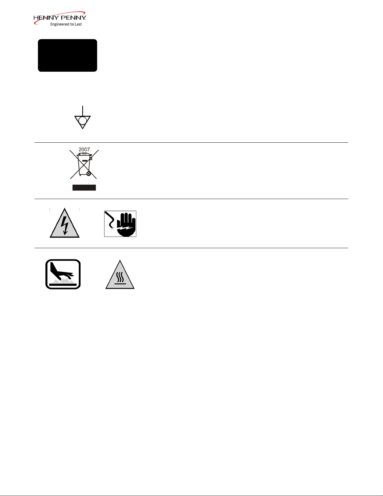
Equipotential Ground Symbol
Waste Electrical and Electronic Equipment (WEEE) Symbol
OR
OR
Shock Hazard Symbols
Hot Surface Symbols
Sept. 2013
3
Page 4
2-1.
TROUBLE
SHOOTING GUIDE
Problem Cause Correction
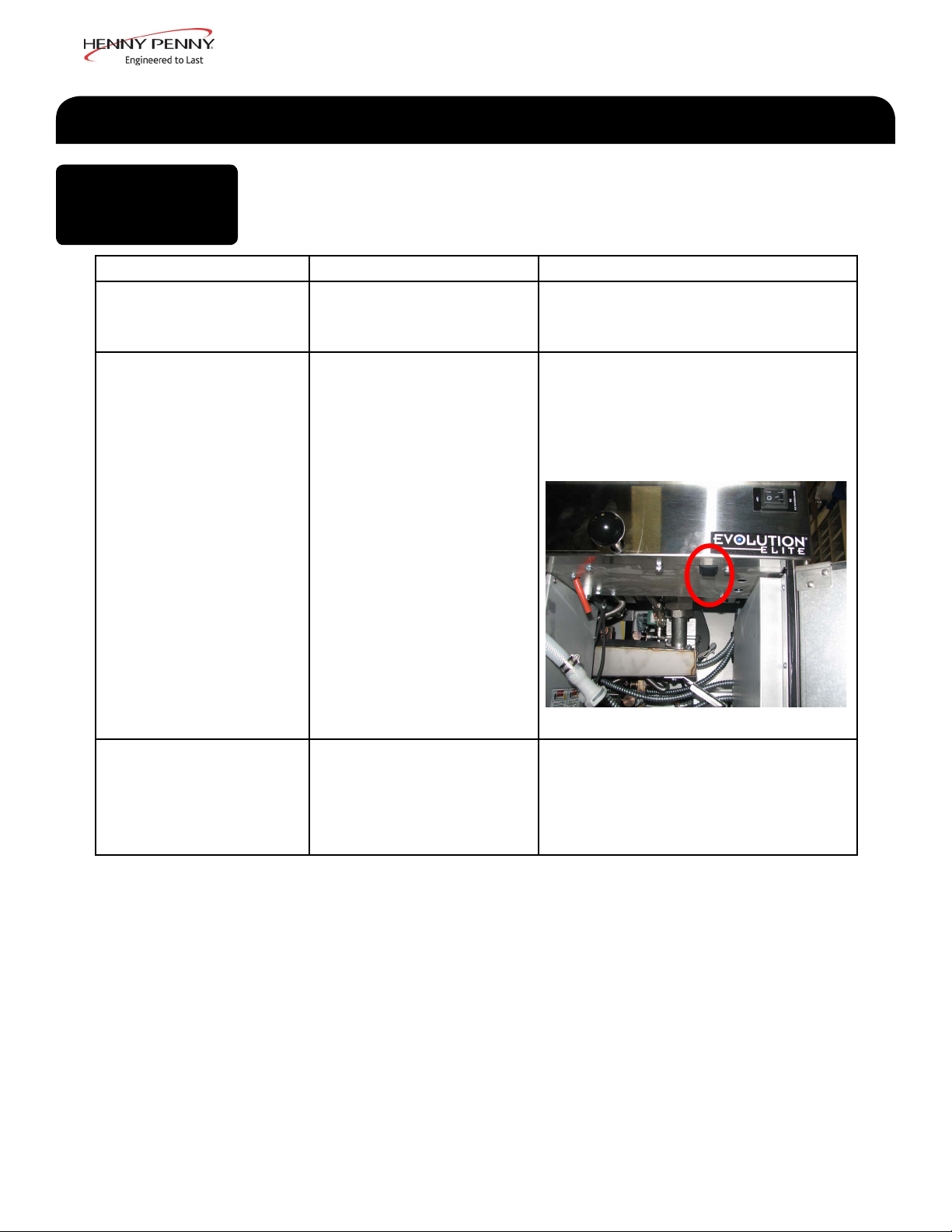
POWER switch ON
but fryer completely
inoperative
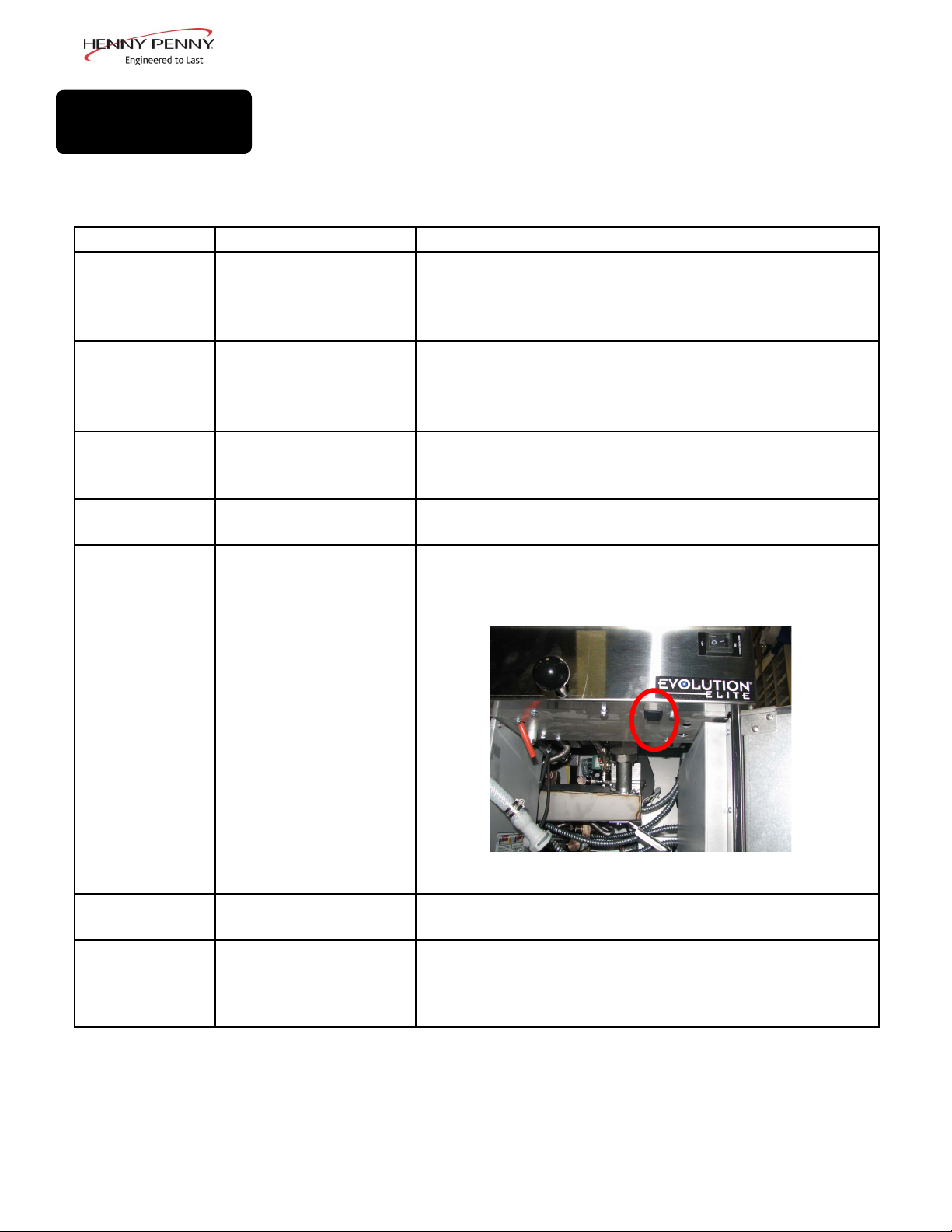
Control error code “E10”
SECTION 2: TROUBLESHOOTING
• Open circuit • Plug fryer in
• Check breaker or fuse at supply
box
• Oil temperature too
high
• Let unit cool down (15-20
minutes), push up on metal reset
button under right side of the
controls; if high limit does not
reset, high limit must be replaced
Vatisunder-lled • JIB is low or empty
• JIB oil line is clogged
or collapsed
• Filter pan needs
cleaned
• Fill the JIB
• Check JIB line
• Cleanlterpanandchange
paper or pad
Sept. 2013
4
Page 5
2-1.
TROUBLE
SHOOTING GUIDE
(CONT.)
Problem Cause Correction
Oil foaming or boiling
over top of vat
Oil will not drain from vat • Drain valve clogged with
Filter motor runs but
pumps oil slowly
Bubbles in oil during en-
tirelteringprocess
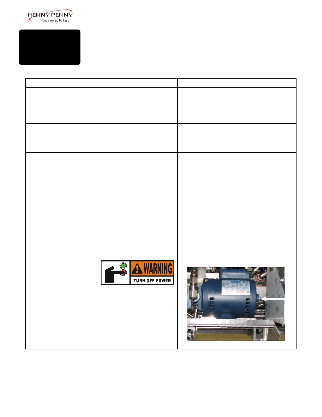
Filter motor will not run • The thermal reset button
• Water in oil
• Improper or bad oil
• Improperltering
• Improper rinsing after
cleaning the vat
crumbs
• Drain trough clogged
• Filter line connections
loose
• Filter paper or pad
clogged
• Filter not reassembled
correctly
• Filter pan not completely
engaged
• Filter pan clogged
• DamagedO-ringonlter
line receiver on fryer
on the rear of the pump
motor is tripped
• Drain and clean oil
• Use recommended oil
• Refertolteringprocedures
• Clean and rinse vat and then dry thor-
oughly
• Open valve, force cleaning brush
through drain
• Remove right side panel and remove
plug from end of trough and clean trough
• Tightenalllterlineconnections
• Changelterpaperorpad
• Refer to assembly instructions on inside
door
• Makesurelterpanreturnlineispushed
completely into the receiver on the fryer
• Clean pan and change paper or pad
• Change O-ring
• Remove the right side panel and
allow time for the motor to cool and
then, using a screwdriver, press hard
against the button until it clicks
Sept. 2013
To prevent burns caused
by splashing shortening,
turn the unit’s POWER
switch to the OFF position
before resetting the lter
pump motor’s manual
reset
protection device.
5
Page 6
2-2.
ERROR CODES
DISPLAY CAUSE CORRECTION
• Control board
“E-4”
overheating
In the event of a control system failure, the digital display shows
an error message. The message codes are shown in the DISPLAY
column below. A constant tone is heard when an error code is displayed, and to silence this tone, press any button.
Turn switch to OFF position, then turn switch back to ON; if
display shows “E-4”, the control board is getting too hot; check
the louvers on each side of the unit for obstructions
• Oil overheating Turn switch to OFF position, then turn switch back to ON; if
“E-5”
display shows “E-5”, the heating circuits and temperature probe
should be checked
“E-6A”
“E-6B”
“E-10”
• Temperature probe
open
• Temperature probe
shorted
Turn switch to OFF position, then turn switch back to ON; if
display shows “E-6A”, the temperature probe should be checked
Turn switch to OFF position, then turn switch back to ON; if
display shows “E-6B”, the temperature probe should be checked
• Hight limit Let unit cool down (15-20 minutes), push up on metal reset
button under right side of the controls; if high limit does not
reset, high limit must be replaced
“E-15”
“E-18-A”
“E-18-B”
“E-18-C”
Sept. 2013
• Drain switch Make sure drain knob is completely pushed-in; if E-15 persists,
have drain switch checked
• LH level sensor open
• RH level sensor open
• Both sensors open
Turn switch to OFF position, then turn switch back to ON;
if display still indicates a failed sensor, have the connectors
checked at the control board; have sensor checked & replace if
necessary
6
Page 7

2-2.
ERROR CODES
(CONT.)
DISPLAY CAUSE CORRECTION
“E-20-A”
“FAN SENSOR
STUCK
CLOSED”
“E-20-B”
“NO DRAFT”
“CHECK FAN”
“E-20-D”
IGNITION
FAILURE”
• Pressure Switch failure
• Wiring problem
• I/O board failure
• Pressure switch failure/
hose loose
• Draft fan failure/ low
voltage
• Flue or hood
obstruction
• Failure to ignite/ no
flame sense
• If fan is not running, have pressure switch checked; should
be open circuit if no air pressure
• If fan is running, wiring error, or relay on I/O board closed
• Press power button to vat off and back on again, if E-20-B
persists, have pressure switch checked; should be open
circuit if no air pressure; make sure hose is connected to fan
and pressure switch
• Have draft fan checked; low voltage going to fan
• Check the fryer flue and hood system for obstructions
• Press power button to vat off and back on again, if E-20-D
persists, check gas line connections; check gas shut-off valve;
have ignition module checked; gas valve checked; flame
sensor gap checked; gas valve and ignition module wiring
checked
• Slow heat recovery • Have a certified service technician check the fryer for correct
“E-21”
“E-22”
“NO HEAT”
“CHECK GAS
VALVE”
• Burner not igniting • Have gas valve and heat circuit checked
voltage to the unit; have heat circuit checked; have unit
checked for loose or burnt wire
• Programming failure • Press power button to vat off and back on again, if any of
“E-41 “ / “E-46”
“E-47”
“E-48”
“E-54-C”
“E-60”
“FILTER IN
USE”
“E-70C”
“E-83-A”
“E-83-B”
• Analog converter
chip or 12 volt supply
failure
• Input system error • Have PC board replaced
• Temperature input
error
• AIF PC board not
communicating with
control PC board
• Drain valve jumper
wire missing or
disconnected
• Pressure too high • Check filter system in Vat #1
• Pressure too high • Check filter system in Vat #2
the error codes, have the controls re-initialized; if error code
persists, have the control board replaced
• Press power button to vat off and back on again, if “E-47”
persists, have the I/O board, or the PC board replaced; if
speaker tones are quiet, probably I/O board failure; have the
I/O board replaced
• Turn switch to OFF, then back to ON; have control PC board
replaced if “E-54C” persists
• Press power button to turn vat off, wait 15 seconds, and turn
back on again. If “E-60” persists, have connector between
the PC boards checked; replace AIF PC board or control PC
board, if necessary
• Have the jumper wire checked on the PC board at drain
switch interlock position
Sept. 2013
7
Page 8

2-2.
ERROR CODES
(CONT.)
DISPLAY CAUSE CORRECTION
“E-83-C” • Pressure too high • Check filter system in Vat #3
“E-83-D”
“E-83-E”
“E-83-J”
“E-83-R”
“E-93-1”
“24 VDC
SUPPLY
TRIPPED”
• Pressure too high • Check filter system in Vat #4
• Pressure too high • Check filter system in Vat #5
• Bulk JIB FILL switch
ON when pressure too
high
• Bulk Dispose switch
ON when pressure too
high
• Autolift motor
malfunction or failure
• Check JIB fill valves
• Check Bulk Dispose quick-disconnect behind fryer
• If AutoLift feature is not operating, have each of the AutoLift
motors checked.
Sept. 2013
8
Page 9

DIAG-120/230/1-EEG FF CONFIG
Sept. 2013
9
Page 10

1.
SECTION 3: PARTS
2.
3.
4.
5.
10.
Item No. Part No. Description Quantity
9.
11.
8.
6.
7.
1 152508 HANGER-BASKET-EEGXX4 ............................................... 1/ 4-well
1 152793 HANGER-BASKET-EEGXX3 ............................................... 1/ 3-well
2 76555 WELD ASSY-COVER FULL ................................................. 1/vat
3 81980 LED-5MM BLUE ................................................................... 1/vat
4 -------- DRAIN KNOB ASSEMBLY................................................... 1/vat
--See DRAIN KNOB drawing for breakdown
5 77575 CASTER-SWIVEL W/ BRAKE (front) .................................. 2
6 77679 CASTER-SWIVEL W/O BRAKE (back) ............................... 2
7 151704 STUD ASSY-JIB SHELF ........................................................ 1
8 52224 COVERED POWER SWITCH ............................................... 1
9 81915 BASKET-1/2 SIZE BLK FRONT SUPP ................................. A/R
9 85136 BASKET-FULL SIZE BLACK FR SPRT ............................... A/R
10 152634 DRAIN PAN ASSY ................................................................. 1
11 96687 ASSY-CHILI CONTROL-EEX16X ....................................... 1/well
11 96862 ASSY-MAGGIANO CONTROL-EEX16X ............................ 1/well
Recommend Parts: A=Truck Stock/B=Dist. Stock / *not shown/ A/R=As Required
Sept. 2013
10
Page 11

10.
1.
2.
3.
4.
5.
6.
8. 9.
7.
Item No. Part No. Description Quantity
1 152634 ASSY-EEG-16X DRAIN PAN W/ CASTER.......................... 1
2 152635 --ASSY-EEG-16X DRAIN PAN COVER .............................. 1
3 85507 --WELD ASSY-CRUMB CATCHER ..................................... 1
4 85503 --WELD ASSY-FILTER WEIGHT ......................................... 1
5 85519 --FILTER SECTION ............................................................... 1
6 95842 --ASSY-DRAIN PAN .............................................................. 1
7 19004 ----CASTER-SWIVEL 2IN ..................................................... 4
8 SC01-009 ----SCREW 1/4-20 X 1/2 THD ............................................... 4/wheel
9 NS04-005 ----LOCKNUT1/4-20 .............................................................. 4/wheel
10 86349 O-RING-116 SUCTION LINE ............................................... 3
Recommend Parts: A=Truck Stock/B=Dist. Stock / *not shown/ A/R=As Required
Sept. 2013
11
Page 12

1.
2.
Item No. Part No. Description Quantity
A 1 92717 THERMOCOUPLE- HIGH LIMIT ........................................ 1/vat
2 87739 ASSY-PROBE ......................................................................... 1/well
150300
ASSY-LH DOOR
(long)
ASSY-LH DOOR
Door
150300 93370 93369 150624 39752
93355 93370 93369 85409 39752
93355 93370 93369 85409 39752
93356 93369 93370 150625 39752
150300
(long)
EEG-164 Door Break Down
93355
ASSY-LH DOOR
(short)
EEG-163 Door Break Down
ASSY-LH DOOR
Door Hinge Chart
Top Hinge
(Door)
ASSY-LH DOOR
93355
(short)
Bottom Hinge
(Door)
93355
(short)
ASSY-RH DOOR
Bottom Hinge
(Frame)
93356
ASSY-RH DOOR
93356
Bushing
Recommend Parts: A=Truck Stock/B=Dist. Stock / *not shown/ A/R=As Required
Sept. 2013
12
Page 13

1.
8.
4.
2.
3.
7.
5.
Item No. Part No. Description Quantity
B 1 87648-001 ASSY-GAS VALVE FULL NAT ............................................. 1/vat
B 1 87663-003 ASSY-GAS VALVE FULL LP ................................................ 1/vat
2 152899 BURNER-PILOT .................................................................... 1/ 2-well
3 PILOT KIT (See next page for kit numbers)
3 152747-001 --INLET-FITTING PILOT ORIFICE (NAT) .......................... 1/vat
3 152747-002 --INLET-FITTING PILOT ORIFICE (LP) ............................. 1//vat
4 76921-001 ORIFICE - BURNER (NAT)................................................... 4/burner
4 76921-002 ORIFICE - BURNER (LP) ...................................................... 4/burner
5 ------ FLEX TUBE (see flex tube chart for length/part number) ...... --
6 84391 ASSY-TRANSFORMER-120V .............................................. 1/well
7 82491 TUBE-1/4 X 12 FLEX SS PILOT ........................................... 1/ 2-well
8 89624-001 CONTROL-WATLOW HL ..................................................... 1/vat
9* 84987 SWITCH-HL ........................................................................... 1/well
10* 76978 SENSOR-FLAME ................................................................... 1/vat
6.
Recommend Parts: A=Truck Stock/B=Dist. Stock / *not shown/ A/R=As Required
May2014
13
Page 14

Kit Number Description
140282 KIT-EEG16X OIL TST/BOILOUT PKT
140283 KIT-EEG16X FRYER SUPPLY (Chili's)
140289 KIT-REPL FULL POT ASSY-EEG2XX
140290 KIT-NAT TO LP F UP TO 5000 FT
140291 KIT-LP TO NAT F UP TO 5000 FT
140295 KIT-EEG16X FRYER SPLY-MAGGIANO
140296 KIT-EEG16X/2XX NAT BASO PILOT
140297 KIT-EEG16X/2XX LP BASO PILOT
140307 KIT-EEG16X BULK DISPOSE/FILL
Sept. 2013
14
Page 15

1. 2.
5.
3. 4.
Item No. Part No. Description Quantity
1 79213 TRANSDUCER-PRESSURE 30 PSI...................................... 1
2 92963-001 BLOWER MOTOR-FLUE EXHAUST 115V ........................ 1/well
3 ------ FLEX TUBE (see flex tube chart for length/part number) ...... --
4 152902-001 CORD-POWER ....................................................................... 1
5 151744 VALVE-120V SOLENOID 1/2NPT ........................................ 1/vat
6* 151725 ASSY-POT CHECK VALVE .................................................. 1/vat
7* 73473 PUMP-OIL TOP OFF 120V .................................................... 1
Recommend Parts: A=Truck Stock/B=Dist. Stock / *not shown/ A/R=As Required
April2014
15
Page 16

1. 2.
3. 4.
5.
6. 7.
8.
Item No. Part No. Description Quantity
1 151727 VALVE-DRAIN 1 1/2 NPT & CAM LOCK ........................... 1/vat
2 NS03-103 NUT-CASTLE 1/2-20 18-8 STEEL ........................................ 1/vat
17255 --PIN-COTTER ....................................................................... 1/vat
3 76948 O-RING -325 ........................................................................... 1/vat
4 151106 ARM-PIVOT ........................................................................... 1/vat
5 PN01-012 CLEVIS PIN 1/4 X 1 IN. SS ................................................... 1/vat
6 151156 PIVOT BUSHING ROD LINKAGE ...................................... 1/vat
7 150181 SPACER-DRAIN ROD LINKAGE ........................................ 1/vat
8 PN01-039 PIN-COTTER .......................................................................... 1/vat
9* 50764 MICROSWITCH-RIGID LEVER .......................................... 1/var
Recommend Parts: A=Truck Stock/B=Dist. Stock / *not shown/ A/R=As Required
April2014
16
Page 17

FLEX TUBE NUMBERS
Part Number
Flex Tube Length
77523-001 12.0
77523-002 18.0
77523-003 24.0
77523-004 30.0
77523-005 36.0
77523-006 42.0
77523-007 48.0
77523-008 7.0
77523-009 13.0
77523-010 54.0
77523-011 10.0
77523-012 13.0
77523-013 14.0
77523-014 28.0
77523-015 32.0
77523-016 16.0
(in.)
3.
1.
2.
Item No. Part No. Description Quantity
1 151534-001 ASSY-FILTER PUMP MOTOR EEG16X 60HZ .................... 1
67583 --MOTOR-1/2 HP FILTER PUMP .......................................... 1
17437 --ASSY-SUB PUMP 5 GPM ................................................... 1
17476 --SEAL KIT ............................................................................. 1
2 87511 SWITCH-DRAIN PAN ........................................................... 1
3 151686-002 HOSE-OIL DISPOSE (34in) ................................................... 1
4* 90506-001 VALVE-CHECK SAE 12-3PSI ............................................... A/R
5* FP01-256 FTG-12 SAE 1/2 NPT ............................................................. A/R
6* FP01-283 FTG-12 SAE 8 45 DEG FLARE SWVL ................................. A/R
Recommend Parts: A=Truck Stock/B=Dist. Stock / *not shown/ A/R=As Required
May2014
17
Page 18

1. 2. 3. 4. 5.
Item No. Part No. Description Quantity
1 ME90-008 P&B T92 RELAY 12VDC COIL 30AMP ............................... 1
2 84454 ASSY-EVOLUTION ELITE AIF PCB ................................... 1
3 77992 SWITCH-PRESSURE 0.80 ..................................................... 1/vat
4 77839 MODULE-IGNITION NON CE ............................................. 2/well
5 60818 RELAY - 24VAC COIL ........................................................... 1/well
Recommend Parts: A=Truck Stock/B=Dist. Stock / *not shown/ A/R=As Required
Sept. 2013
18
 Loading...