

Page 1

Reduced Oil Capacity Open Fryers
(Split Vat & Full Vat– Gas)
Henny Penny
Evolution Elite™
Model EEG-142
Model EEG-143
Model EEG-144
TECHNICAL MANUAL
Page 2

Page 3

Model EEG-142, 143, 144
TABLE OF CONTENTS
Section Page
Section 1. TROUBLESHOOTING ................................................................................... 1-1
1-1 Introduction .................................................................................................. 1-1
1-2 Safety ............................................................................................................ 1-1
1-3 Troubleshooting ............................................................................................ 1-2
1-4 Error Code Table .......................................................................................... 1-7
Section 2. INFO & FILTER BUTTON STATS ................................................................. 2-1
2-1 INFO Button Stats ........................................................................................ 2-1
2-2 FILTER Button Stats .................................................................................... 2-1
Section 3. INFORMATION MODE ............................................................................... 3-1
3-1 Information Mode Details .............................................................................3-1
Section 4. Product Program Mode ................................................................................. 4-1
4-1 Modifying Product Settings ........................................................................... 4-1
Section 5. LEVEL 2 PROGRAMMING ........................................................................... 5-1
5-1 Special Program Mode ...................................................................................5-1
5-2 Clock Set ........................................................................................................ 5-10
5-3 Data Logging, Heat Control, Tech, Stat & Filter Control Modes ..................5-10
5-4 Tech Mode ...................................................................................................... 5-11
5-5 Stats Mode ...................................................................................................... 5-17
Section 6. MAINTENANCE SECTION ...................................................................................... 6-1
6-1 Introduction .............................................................................................................. 6-1
6-2 Maintenance Hints ................................................................................................... 6-1
6-3 Preventive Maintenance ........................................................................................... 6-1
6-4 Control Panel and Menu Card Replacement ............................................................ 6-2
6-5 High Temperature Limit Control ............................................................................. 6-3
6-6 Main Power switch................................................................................................... 6-5
6-7 Probe Replacement .................................................................................................. 6-6
FM06-040
Revised 3-17-14
iNov. 2009
Page 4

Model EEG-142, 143, 144
TABLE OF CONTENTS
Section Page
Section 6. MAINTENANCE SECTION (Continued)
6-8 Solenoid Valves .............................................................................................. 6-9
6-9 Oil Channel Clean-Out ................................................................................... 6-11
6-10 Filter Pump & Motor ...................................................................................... 6-12
6-11 JIB Pump ........................................................................................................ 6-14
6-12 Express Filter PC Board ................................................................................. 6-14
6-13 Transformers .................................................................................................. 6-15
6-14 Filter Motor Relay .......................................................................................... 6-16
6-15 Gas Control Valves ......................................................................................... 6-16
6-16 Blower Motor ................................................................................................. 6-18
6-17 Drain Pan Switch ............................................................................................ 6-19
6-18 Filter Beacon .................................................................................................. 6-20
6-19 Air Pressure Switches ..................................................................................... 6-21
6-20 Ignitor & Flame Sensor Assembly ................................................................. 6-22
6-21 Ignition Modules ............................................................................................ 6-23
6-22 Pressure Transducer ........................................................................................ 6-24
Wiring Diagrams & Schematics
Section 7. PARTS SECTION
7-1 Introduction .................................................................................................... 7-1
7-2 Genuine Parts ................................................................................................. 7-1
7-3 How To Order ................................................................................................. 7-1
7-4 Prices .............................................................................................................. 7-1
7-5 Delivery .......................................................................................................... 7-1
7-6 Warranty ......................................................................................................... 7-1
iiNov. 2009
Page 5
SECTION 1. TROUBLESHOOTING
Model EEG-142, 143, 144
1-1. INTRODUCTION
1-2. SAFETY
This section provides troubleshooting information in the form
of an easy to read table.
If a problem occurs during the rst operation of a new fryer,
recheck the installation per the Installation Section of this
manual.
Before troubleshooting, always recheck the operation
procedures per Section 3 of this manual.
Where information is of particular importance or safety related,
the words DANGER, WARNING, CAUTION, and NOTICE
are used. Their usage is described below.
SAFETY ALERT SYMBOL is used with DANGER,
WARNING, or CAUTION which indicates a personal
injury type hazard.
NOTICE is used to highlight especially important
information.
CAUTION used without the safety alert symbol indicates a
potentially hazardous situation which, if not avoided, may
result in property damage.
CAUTION indicates a potentially hazardous situation
which, if not avoided, may result in minor or moderate
injury.
WARNING indicates a potentially hazardous situation
which, if not avoided, could result in death or serious
injury.
DANGER INDICATES AN IMMINENTLY
HAZARDOUS SITUATION WHICH, IF NOT
AVOIDED, WILL RESULT IN DEATH OR SERIOUS
INJURY.
1-1Aug. 2007
Page 6

Model EEG-142, 143, 144
1-3. TROUBLESHOOTING
To isolate a malfunction, proceed as follows:
1. Clearly dene the problem (or symptom) and when it
occurs.
2. Locate the problem in the Troubleshooting table.
3. Review all possible causes. Then, one-at-a-time work
through the list of corrections until the problem is solved.
4. Refer to the maintenance procedures in the Maintenance
Section to safely and properly make the checkout and repair
needed.
If maintenance procedures are not
followed correctly, injuries and/or
property damage could result.
1-2Aug. 2007
Page 7

Model EEG-142, 143, 144
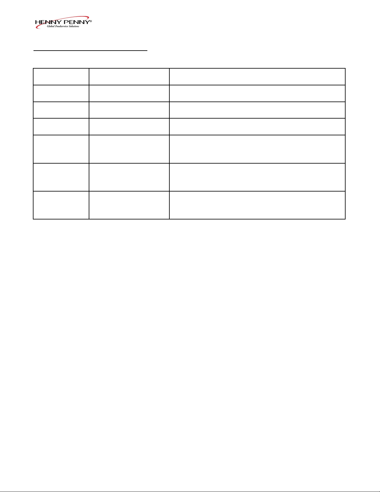
7-1. TROUBLE SHOOTING
(Continued)
Problem Cause Correction
POWER switch ON
but fryer completely
• Open circuit • Plug fryer in
• Check breaker or fuse at supply box
inoperative
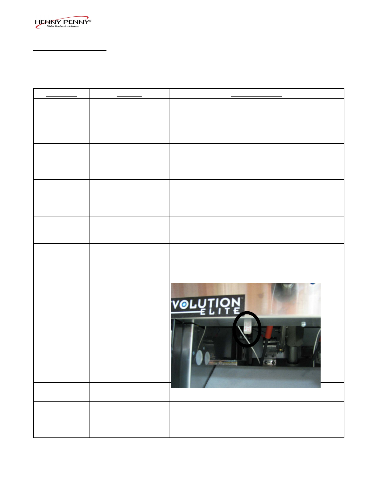
Control error code “E-10” • Oil temperature too high • Let unit cool down (15-20 minutes),
push up on metal reset button under
right side of the controls; if high
limit does not reset, high limit must
be replaced
Vat is under-lled • JIB is low or empty
• JIB oil line is clogged or
collapsed
• Filter pan needs cleaned
1-3July 2008
• Fill the JIB
• Check JIB line
• Clean lter pan and change paper or
pad
Page 8
7-1. TROUBLE SHOOTING
(Continued)
Problem Cause Correction
Oil foaming or boiling over
top of vat
Oil will not drain from vat • Drain valve clogged with
Filter motor runs but pumps
oil slowly
Bubbles in oil during entire
ltering process
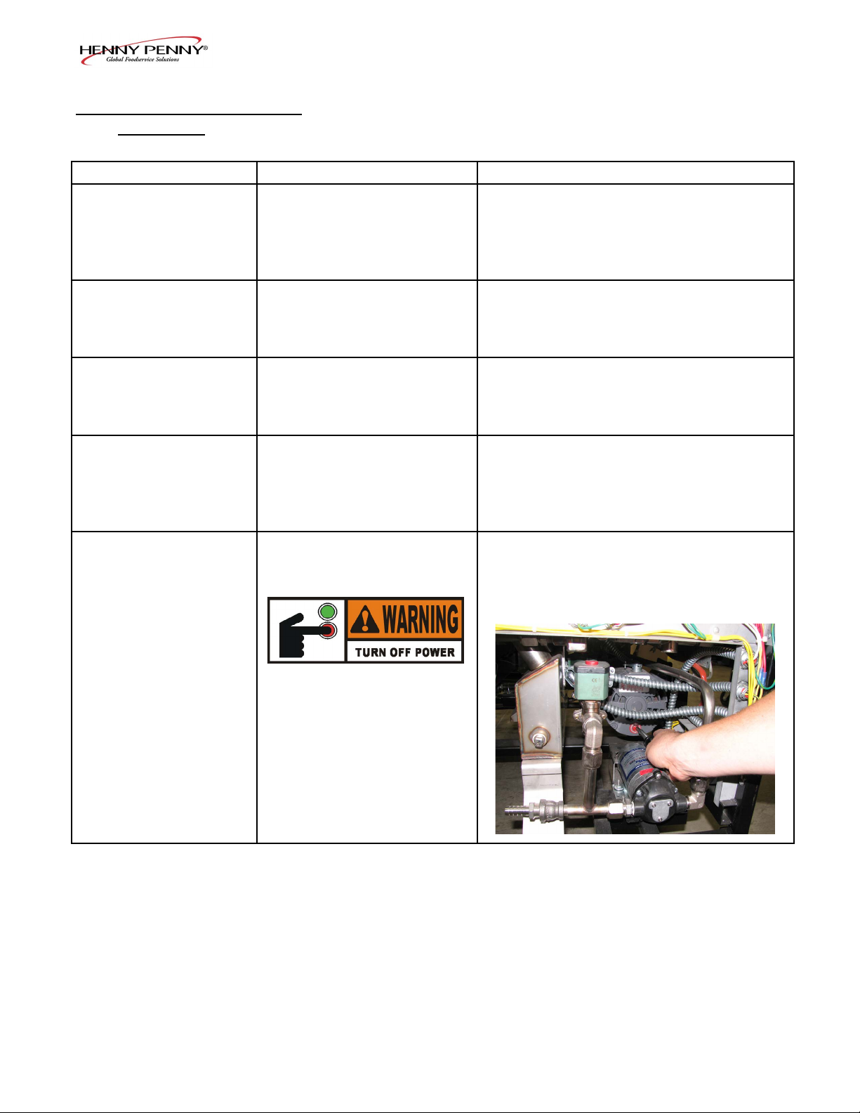
Filter motor will not run • The thermal reset button on
• Water in oil
• Improper or bad oil
• Improper ltering
• Improper rinsing after
cleaning the vat
crumbs
• Drain trough clogged
• Filter line connections loose
• Filter paper or pad clogged
• Filter not reassembled
correctly
• Filter pan not completel
engaged
• Filter pan clogged
• Damaged O-ring on lter line
receiver on fryer
the rear of the pump motor is
tripped
Model EEG-142, 143, 144
• Drain and clean oil
• Use recommended oil
• Refer to ltering procedures
• Clean and rinse vat and then dry thoroughly
• Open valve, force cleaning brush through
drain
• Remove right side panel and remove plug
from end of trough and clean trough
• Tighten all lter line connections
• Change lter paper or pad
• Refer to assembly instructions on inside door
• Make sure lter pan return line is pushed
completely into the receiver on the fryer
• Clean pan and change paper or pad
• Change O-ring
• Remove the right side panel and allow
time for the motor to cool and then, using
a screwdriver, press hard against the
button until it clicks
To prevent burns caused by
splashing shortening, turn
the unit’s POWER switch
to the OFF position before
resetting the lter pump
motor’s manual reset
protection device.
1-4July 2008
Page 9
Model EEG-142, 143, 144
1-4. ERROR CODES
In the event of a control system failure, the digital display
shows an error message. The message codes are shown in the
DISPLAY column below. A constant tone is heard when an error code is displayed, and to silence this tone, press any button.
DISPLAY CAUSE CORRECTION
“E-4”
• Control board
overheating
Turn switch to OFF position, then turn switch back
to ON; if display shows “E-4”, the control board is
getting too hot; check the louvers on each side of
the unit for obstructions
“E-5”
• Oil overheating
Turn switch to OFF position, then turn switch back
to ON; if display shows “E-5”, the heating circuits
and temperature probe should be checked
“E-6A”
• Temperature probe
open
Turn switch to OFF position, then turn switch back
to ON; if display shows “E-6A”, the temperature
probe should be checked
“E-6B”
• Temperature probe
shorted
Turn switch to OFF position, then turn switch back
to ON; if display shows “E-6B”, the temperature
probe should be checked
“E-10”
• Hight limit
Let unit cool down (15-20 minutes), push up on
metal reset button under right side of the controls;
if high limit does not reset, high limit must be
replaced
“E-15” • Drain switch Make sure drain knob is completely pushed-in; if E-15
persists, have drain switch checked
“E-18-A”
“E-18-B”
“E-18-C”
• LH level sensor open
• RH level sensor open
• Both sensors open
Turn switch to OFF position, then turn switch back to
ON; if display still indicates a failed sensor, have the
connectors checked at the control board; have sensor
checked & replace if necessary
1-5Sept. 2009
Page 10
1-4. ERROR CODES (Continued)
Model EEG-142, 143, 144
“E-20-A”
“FAN SENSOR
STUCK
CLOSED”
“E-20-B”
“NO DRAFT”
“CHECK FAN”
“E-20-D”
IGNITION
FAILURE”
“E-21”
“E-22”
“NO HEAT”
“CHECK GAS
VALVE”
“E-41 “ / “E-46”
“E-47”
“E-48”
“E-54-C”
“E-60”
“FILTER IN USE”
“E-70C”
“E-83-A”
• Pressure Switch
failure
• Wiring problem
• I/O board failure
• If fan is not running, have pressure switch
checked; should be open circuit if no air
pressure
• If fan is running, wiring error, or relay on I/O board
closed
• Pressure switch
failure/ hose loose
• Draft fan failure/ low
voltage
• Flue or hood
obstruction
• Failure to ignite/ no
ame sense
• Press power button to vat off and back on again,
if E-20-B persists, have pressure switch checked;
should be open circuit if no air pressure; make sure
hose is connected to fan and pressure switch
• Have draft fan checked; low voltage going to fan
• Check the fryer ue and hood system for obstructions
• Press power button to vat off and back on again, if
E-20-D persists, check gas line connections; check
gas shut-off valve; have ignition module checked;
gas valve checked; ame sensor gap checked; gas
valve and ignition module wiring checked
• Slow heat recovery • Have a certied service technician check the fryer for
correct voltage to the unit; have heat circuit checked;
have unit checked for loose or burnt wire
• Burner not igniting
• Have gas valve and heat circuit checked
• Programming failure • Press power button to vat off and back on again,
if any of the error codes, have the controls reinitialized; if error code persists, have the control
board replaced
• Analog converter
chip or 12 volt
supply failure
• Press power button to vat off and back on again,
if “E-47” persists, have the I/O board, or the
PC board replaced; if speaker tones are quiet,
probably I/O board failure; have the I/O board
replaced
• Input system error
• Temperature input
error
• AIF PC board not
communitcating with
control PC board
• Have PC board replaced
• Turn switch to OFF, then back to ON; have
control PC board replaced if “E-54C” persists
• Press power button to turn vat off, wait 15 seconds,
and turn back on again. If “E-60” persists, have
connector between the PC boards checked; replace
AIF PC board or control PC board, if necessary
• Drain valve jumper
wire missing or
• Have the jumper wire checked on the PC board at
drain switch interlock position
disconnected
• Pressure too high • Check lter system in Vat #1
1-6Sept. 2009
Page 11
1-4. ERROR CODES (Continued)
Model EEG-142, 143, 144
“E-83-B”
“E-83-C”
“E-83-D”
“E-83-E”
“E-83-J”
“E-83-R”
“E-93-1”
“24 VDC SUPPLY
TRIPPED”
• Pressure too high
• Check lter system in Vat #2
• Pressure too high • Check lter system in Vat #3
• Pressure too high
• Check lter system in Vat #4
• Pressure too high • Check lter system in Vat #5
• Bulk JIB FILL
• CheckJIBllvalves
switch ON when
pressure too high
• Bulk Dispose switch
ON when pressure
• Check Bulk Dispose quick-disconnect behind
fryer
too high
• Autolift motor
malfunction or
• If AutoLift feature is not operating, have each of the
AutoLift motors checked.
failure
1-7Aug. 2012
Page 12
SECTION 2. INFO & FILTER BUTTON STATS
Model EEG-142, 143, 144
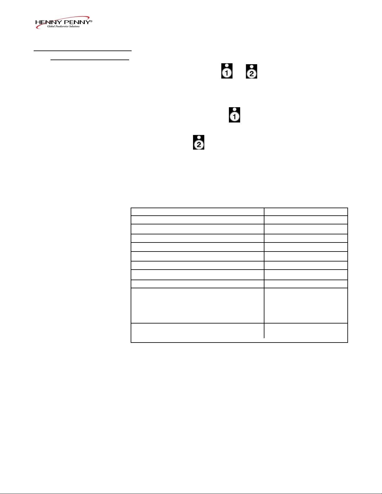
2-1. INFO BUTTON STATS
Actual Oil Temperature
1. Press and the actual oil temperature shows in the
display, for each vat.
Set-point Temperature
1. Press twice and SP shows in the display, along with
the set-point (preset) temperature of each vat.
Recovery Information for each Vat
1. Press 3 times and REC shows in the left display and
the recovery time that oil temperature went from 250°F
(121°C) to 300°F (149°C) shows in the right display. For
example, means it took 5 minutes and
REC 5:30
30 seconds for the oil temperature to recover to 300°F
(149°C) from 250°F (121°C).
If no buttons are pressed within 5 seconds in
any of stats modes, the controls revert back to
normal operation.
2-2. FILTER BUTTON STATS
Cook Cycles Remaining before Filtering
1. Press and release either button and the left display
shows “COOKSREMAINING” and the right display shows
the number of cook cycles before the next auto lter. For
example.
REMA INING
3 6
means after 3 more cook cycles on the left vat, the controls
asks the operator if they are ready to lter or not. But, 6
more cook cycles remain on the right vat.
Time and Date
2. Press either twice and ‘FILTERED” shows in the
diplays, along with the time-of-day and date of the last
lter.
2-1Nov. 2009
Page 13
SECTION 3. INFORMATION MODE
This historic information can be recorded and used for
operational and technical help and allows you to view the
following:
• 1. E-LOG • 9. CPU TEMP
• 2. LAST LOAD • 10. COMMUNICATION INFO
• 3. DAILY STATS • 11. ANALOG INFO
• 4. OIL STATS • 12. ACTIVITY LOG
• 5. REVIEW USAGE • 13. OIL LEVELS
• 6. INPUTS • 14. PUMP VALVE INFO
• 7. OUTPUTS • 15. AIF INFO
• 8. OIL TEMP
Not all Information Mode functions are discussed in this
section. To ensure proper operation of fryer, please consult
Henny Penny Corp. before changing any of these settings. For
more information on these functions, contact Technical Support
at 1-800-417- 8405, or 1-937-456-8405.
Model EEG-142, 143, 144
3-1. INFORMATION MODE
DETAILS
1. E-LOG (error code log)
Press and buttons at the same time and “*INFO
MODE*” shows in the display, followed by “1. E-LOG”.
Press and to exit Information Mode at any time.
Press ▼ and “A. (date & time) *NOW* show in displays.
This is the present date and time.
Press ▼ and if a error was recorded, “B. (date, time, and
error code information)” shows in display. This is the latest
error code that the controls recorded.
Press ▼ and the next latest error code information can be seen.
Up to 10 error codes (B to K) can be stored in the E-LOG
section.
3-1Nov. 2009
Page 14
Model EEG-142, 143, 144
3-1. INFORMATION MODE
DETAILS (Continued)
2. LAST LOAD (Information on recent cook cycles)
Press ► and “2. LAST LOAD” show in displays.
Press a timer button or for the product you want to
view the cook data and the LED ashes.
Press ▼ button to start viewing the cook data.
For example, if the left LED is ashing, “PRODUCT
FRY L1” show in displays.
If the right LED is ashing, “PRODUCT FRY R2” show
in displays.
Press ▼ button to start viewing the cook data.
FUNCTION DISPLAY EX:
Product (Last product cooked) PRODUCT FRY L1
Time of day the last Cook Cycle was started STARTED FEB 4
2:25P
Actual Elapsed cook Time (Real seconds) ACTUAL TIME 1:06
Programmed cook Time PROG TIME 1:00
Max Temp during Cook Cycle MAX TEMP 350°F
Min Temp during Cook Cycle MIN TEMP 313°F
Avg Temp during Cook Cycle AVG TEMP 322°F
Heat On (percentage) during Cook Cycle HEAT ON 45%
Ready? (Was fryer Ready before start?) READY? YES
When Cook Cycle was stopped: Early QUIT AT 0:10 REM
After complete Cook Cycle OR
*DONE* +6 SEC
Difference (%) between actual and ACT/PROG 1%
programmed cook time
3-2Nov. 2009
Page 15
Model EEG-142, 143, 144
3-1. INFORMATION MODE
DETAILS (Continued)
3. DAILY STATS (Operational info of fryer for last 7 days)
Press ► and “3. DAILY STATS” show in displays.
Press ▼ button to start viewing the cook data.
Press the right to view data for other days of week.
FUNCTION DISPLAY EX:
Day this data was recorded for APR-30 TUE*
Number of Hours:Minutes the fryer was on (L/R) ON HRS TUE* 3:45
Number of times ltered (L/R) FILTERED TUE* 4
Number of times lter skipped (L/R) SKIPPED TUE* 4
Number of times oil added (L/R) ADD OIL TUE* 4
Number of times oil discarded (L/R) DISPOSE TUE* 0
Oil temperature recovery time (L/R) RECOVERY TUE*1:45
Total number of cook cycles that day (L/R) TOT CK TUE* 38
Number of cycles stopped before *DONE* QUIT CK TUE* 2
Cook Cycles for Product #1 TUE* COOK -1- 17
Cook Cycles for Product #2 TUE* COOK -2- 9
Cook Cycles for Product #3 TUE* COOK -3- 5
Cook Cycles for Product #4 TUE* COOK -4- 0
Cook Cycles for Product #5 TUE* COOK -5- 0
Cook Cycles for Product #6 TUE* COOK -6- 6
Cook Cycles for Product #7 TUE* COOK -7- 0
Cook Cycles for Product #8 TUE* COOK -8- 0
Cook Cycles for Product #9 TUE* COOK -9- 1
Cook Cycles for Product #0 TUE* COOK -0- 0
3-3Nov. 2009
Page 16
Model EEG-142, 143, 144
3-1. INFORMATION MODE
DETAILS (Continued)
4. OIL STATS
(info of current oil and avg. of last 4 batches of oil)
Press ► and “4. OIL STATS” show in displays.
Press ▼ button to start viewing the cook data.
FUNCTION DISPLAY EX:
Start date of new oil NEW OIL MAR-23
Number of days oil in use (L/R) OIL USE 4 DAYS
Number of lters on this oil (L/R) FILTERED 4
Number of times lter skipped (L/R) SKIPPED 0
Number of cook cycles on this oil (L/R) TOT CK 38
Average number of days per oil change (L/R) AVG DAYS
PER OIL CHANGE 13.8 DAYS
Average number cook cycles per oil change (L/R) AVG CKS PER
OIL CHANGE 388 CKS
Press and hold a product button (1 to 4) to view the data from
one of the previous 4 batches of oil used.
Press to view oldest oil data: Ex: OIL-4 14 DAYS
Press to view 3rd oldest oil data: Ex: OIL-3 12 DAYS
Press to view 2nd oldest oil data: Ex: OIL-2 15 DAYS
Press to view previous batch of oil: Ex: OIL-1 13 DAYS
To obtain the most accurate oil information, use
the “3.DISPOSE” step in the Filter Menu (press
and hold ) to drain the oil from the vat.
3-4Nov. 2009
Page 17
Model EEG-142, 143, 144
3-1. INFORMATION MODE
DETAILS (Continued)
Day the usage data was previously reset SINCE APR-19 3:00P
Number of Hours the fryer was on (L/R) ON HRS 4
Number of times ltered (L/R) FILTERED 4
Number of times lter skipped (L/R) SKIPPED 0
Number of times oil added (L/R) ADD OIL 4
Number of times oil discarded (L/R) DISPOSE 1
Total number of cook cycles (L/R) TOT CK 38
Number of cycles stopped before *DONE* QUIT CK 2
Cook Cycles for Product #1 COOK -1- 17
Cook Cycles for Product #2 COOK -2- 9
Cook Cycles for Product #3 COOK -3- 5
Cook Cycles for Product #4 COOK -4- 0
Cook Cycles for Product #5 COOK -5- 0
Cook Cycles for Product #6 COOK -6- 6
Cook Cycles for Product #7 COOK -7- 0
Cook Cycles for Product #8 COOK -8- 0
Cook Cycles for Product #9 COOK -9- 1
Cook Cycles for Product #0 COOK -0- 0
Reset usage data:
Enter the Usage Code - 1, 2, 3 RESET USAGE /
on this step to zero out all the ENTER CODE -----usage information
5. REVIEW USAGE
(accumulated info since the data was reset)
Press ► and “5. REVIEW USAGE” show in displays.
Press ▼ button to start viewing the cook data.
FUNCTION DISPLAY EX:
3-5Nov. 2009
Page 18
Model EEG-142, 143, 144
3-1. INFORMATION MODE
DETAILS (Continued)
6. INPUTS
Press ► and “6. INPTS” and “HDF” show in displays.
H = HIGH LIMIT - If “H” is present, the high limit is good. If “-”
shows then the high limit is tripped out (overheated) or discon nected.
D = DRAIN SWITCH - If “D” is present, the drain handle (when
applicable) is closed. If “-” shows then the drain is open or the
switch is faulty.
F =FAN (PRESSURE SWITCH) - If “F” is present, the pressure
switch is good. If “-” shows in the display, the switch is faulty.
Press ▼ button and an underscore (“_”) indicates the input is not
presently detected. A Checkmark (“
detecting a normal input. A blinking (“X”) indicates the signal is
presently detected, but is detected as a half-wave (partially failed)
input.
The H, D, F signals above are wired in series. The rst signal missing out of this sequence l generally causes all signals to the right of it
to be missing as well.
√” ) indicates the signal is
7. OUTPUTS
Press ► and “7. OUTP” and “F-S-I-H-” show in displays.
F = FAN (PRESSURE SWITCH)- Press or to open and
close the pressure switches
S = SAFETY GAS VALVE (if available) - Press or to
open and close the gas safety valves
I = IGNITION MODULE - Press or to open and
close the outputs on the ignition modules
H = HEAT OUTPUTS - Press or to turn on and off the
heating outputs (ex: gas valve)
8. OIL TEMPERATURE
Press ► and “8.OIL TMP” shows in the left display and the oil
temperature shows in the right display.
9. CPU TEMPERATURE
Press ► and “9.CPU TMP” shows in the left display and the
current PC board temperature shows in the right display.
3-6Nov. 2009
Page 19
SECTION 4. PRODUCT PROGRAM MODE
This mode allows you to program the following:
• Change Product Name
• Assign Button
• Change Times & Temp
• Change Cook ID
• Alarms
• Quality Timers
• Include in Filter Count (Global)
• Filter at X no. of loads (Mixed)
• Load Compensation
• Load Compensation Reference
• Full Heat
• PC Factor
Model EEG-142, 143, 144
4-1. MODIFYING PRODUCT
SETTINGS
1. Press and hold button until “PROG” shows in the
display, followed by “ENTER CODE”.
2. Enter code 1, 2, 3 (rst 3 product buttons). “PRODUCT”
and “PROGRAM” show in the displays, followed by
“SELECT PRODUCT’ and “-P 1-” (ex: NUG).
Change Product Names
3. Use the ▲and ▼ buttons to scroll through the 40 products,
or press the desired product button.
4. Press ►button and “NAME” shows in the left display
and the product (ex: NUGGETS) shows in the right display.
5. Press √ button and the rst letter in the name ashes.
Press a product button and the ashing letter changes to
the rst letter under the product button that was pressed.
For example, if is pressed, the ashing letter changes
to an “A”.
Press the same button again and the ashing letter changes
to a “B”. Press it again and the ashing letter changes to
a “C”. Once the desired letter shows in the display, press
► button to continue to the next letter and repeat the
procedure.
Press and hold the right X button to exit Program Mode, or
press ► button to continue on to “COOK TIME”.
Assign Button
6. Press ► button until “ASSIGN BTN” shows in the
display, along with the product (ex: NUGGETS). If this
product already has a product button assigned to it, that
LED will be lit. To assign other product buttons to that
product, press and hold the product button for 3 seconds
and that LED stays lit. To remove a product from a button,
press and hold the product button with a lit LED and the
LED goes out.
4-1Nov. 2009
Page 20

Model EEG-142, 143, 144
4-1. MODIFYING PRODUCT
SETTINGS (Continued)
To Change Times and Temperatures
7. Press ► button until “COOK TIME” shows in the display,
and then use the product buttons, or the ▲ and ▼buttons,
to change the time in minutes and seconds, to a maximum
of 59:59.
8. Press ► button and “TEMP” shows in the display, along
with the preset temperature on the right side of the display.
Press the product buttons, or the ▲ and ▼ buttons, to
change the temperature. The temperature range is 190°F
(88°C) to 375°F (191°C).
Cook ID Change
9. Press ► button until “COOK ID” shows in the display
along with the product ID. For example, NUG would be
the ID for nuggets. Use the product buttons, or the ▲ and
▼ buttons, to change the ID.
Alarms (1 & 2)
10. Press ► button until “ALRM 1” shows in the left display,
and an alarm time in the right display. Press the product
buttons, or the ▲ and ▼buttons, to set an alarm.
Ex., If a Cook Cycle was set at 3 minutes, and an alarm
was to go off after 30 seconds into the Cook Cycle, “2:30”
would be set in the display at this time. When the timer
counts down to 2:30 the alarm sounds.
After the alarm time is set, press ► button and “ALRM
2” shows in the display, and a second alarm can be
programmed.
Quality Timer (hold time)
11. Press ► button until “QUAL TMR” shows in the display
along with the preset holding time. Press the product
buttons, or the ▲ and ▼ buttons,to adjust holding time, up
to 59:59.
Global Filter Tracking
Include in Filter Count
12. Press ► button until “INCL IN FLTR CNT” ashes in
the display along with “YES” or “NO”. Using ▲ and ▼
buttons, change the display to “YES” if that product’s Cook
Cycles are to be counted as part of the recommended lter
process. Set to “NO” if it is not to be included. Mixed
Filter Tracking
4-2Nov. 2009
Page 21

Model EEG-142, 143, 144
4-1. MODIFYING PRODUCT
SETTINGS (Continued)
Filter After X Number of Loads
13. Press ► button until “FILTER AFTER...” ashes in the
left display along, and the number of cook cycles between
lters shows in the right display. Press the product buttons,
or the ▲ and ▼ buttons, to change this value of 0 to 99
loads. This needs set for each product.
>Load Compensation, Load Compensation
Reference, Full Heat, PC Factor<
14. Press ► button until “LD COMP” shows in the
display, along with the load compensation value. This
automatically adjusts the time to account for the size and
temperature of the cooking load.
Press the product buttons, or the ▲ and ▼ buttons, to
change this value of 0 to 20.
15. Press ► button until “LCMP REF” shows in the display
along with the load compensation average temperature.
(if load compensation is set to “OFF”, then “_ _ _” shows
in display and setting cannot be programmed) This is the
average cooking temperature for each product. The timer
speeds up at temperatures above this setting and slows
down at temperatures below this setting. Press the product
button, or the ▲ and ▼ buttons, to change this value.
16. Press ► button until “FULL HT” shows in the display
along with the full heat value in seconds, which means
the heat is on as soon as a timer button is pressed, for the
programmed length of time. Press the product buttons,
or the ▲ and ▼ buttons, to change this value of 0 to 90
seconds.
17. Press ► button until “PC FACTR” shows in the display
along with the proportional temperature, which helps to
keep the oil from over-shooting the setpoint temperature.
Press the product buttons, or the ▲ and ▼ buttons, to
change this value of 0 to 50 degrees.
• Use ◄ button to go back to previous menu items.
• Press ► button when nished with the current
product, to return to the “SELECT PRODUCT”
step.
• Press and hold button to exit PRODUCT
PROGRAM Mode.
4-3Nov. 2009
Page 22

SECTION 5. LEVEL 2 PROGRAMMING
5-1. SPECIAL PROGRAM
MODE
Model EEG-142, 143, 144
Used to access the following:
• Special Program Mode
• Clock Set
• Data Communication
• Heat Control
The Special Program Mode is used to set more detailed
programming, such as:
SP-1 • Degrees Fahrenheit or Celsius
SP-2 • Language: English, Russian, Swedish (SVENSKT),
German (DEUTSCHE), Portuguese, Spanish (ESPANOL)
and French (FRANCAIS)
SP-3 • System Initialization (Factory Presets)
SP-4 • Audio Volume
SP-5 • Audio Tone
SP-6 • Melt Cycle Select - 1.LIQUID; 2.SOLID
SP-7 • Idle Mode Enabled - YES or NO
SP-7A • Use “0” for IDLE
SP-7B • Auto Idle Minutes
SP-7C • Idle Set-point Temperature
SP-8 • Filter Tracking Mode - 1.MIXED or 2.GLOBAL
SP-8A • Suggest Filter At... - 75% to 100% (MIXED)
SP-8B • Filter Lockout Enabled? - YES or NO (MIXED)
SP-8A • Left Vat Filter Cycles - 0 to 99 (GLOBAL)
SP-8B • Right Vat Filter Cycles - 0 to 99 (GLOBAL)
SP-8C • Filter Lockout Enabled? - YES or NO (GLOBAL)
SP-9 • Polish Duration - X:XX M:SS
SP-10 • Change Pad Reminder Time - XX HRS
SP-11 • Clean-Out Time - XX MIN
SP-12 • Clean-Out Temperature - XXX
o
F or oC
SP-13 • Cooking User IO - After Cook Cycle, display shows
previous menu item or “----”
SP-14 • Number of Baskets - 2-BASKETS or 4 BASKETS
SP-15 • Show Cooking Indicator - YES or NO
SP-16 • 2nd Language: English, Russian, Swedish (SVENSKT),
German (DEUTSCHE), Portuguese, Spanish (ESPANOL)
and French (FRANCAIS)
SP-17 • 2nd AudioVolume
SP-18 • Energy Save Enabled? - YES or NO
SP-19 • Fryer Type - GAS or ELECTRIC
SP-20 • Vat Type - SPLIT or FULL
SP-21 • Autolift Enabled? - NO LIFT or YES LIFT
SP-22 • Bulk Oil Supply? - YES or NO
SP-23 • Bulk Oil Dispose? - YES or NO
SP-24 • Serial No. of Fryer
SP-25 • Change Mgr. Code- 1 = YES
SP-26 • Change Usage Code - 1 = YES
SP-27 • Dispose Requires Code ? - YES or NO
SP-28 • Longer Fill Time Enabled - YES or NO
SP-29 • Let User Exit Fill? - YES or NO
5-1Nov. 2009
Page 23
Model EEG-142, 143, 144
5-1. SPECIAL PROGRAM
MODE (Continued)
Press and hold the button for 5 seconds until “LEVEL
2”followed by, “SP PROG” and “ENTER CODE” show in the
display.
Enter code 1,2,3, and “SP-1”, “TEMP”, “FORMAT” show in
the displays.
If a bad code is entered, a tone sounds and “BAD
CODE” shows on the display. Wait a few seconds,
the controls revert back to the cook mode, and repeat
the above steps.
To exit from the Special Program Mode at any time,
press and hold button for 2 seconds.
Degrees Fahrenheit or Celsius (SP-1)
The left display ashes “SP-1” and “TEMP”, “FORMAT”.
Press the ▲ or ▼ buttons to choose ºF or ºC.
• Use ◄ button to go back to previous menu items
• Press ► button when nished with the current Level 2
step
Language (SP-2)
Press ► button and “SP-2” and “LANGUAGE” ash on the
left display. Press the ▲ or ▼ buttons to select the desired
language.
System Initialization (SP-3)
Press ► button and “SP-3” and “DO SYSTEM INIT” ash
in the display, along with “INIT” on the right display. To reset
the controls to factory default settings, press and hold √ button
and control counts down “IN 3”, “IN2”, “IN 1”. Once display
shows “-INIT-” & *DONE* the controls are reset to factory
defaults.
Audio Volume (SP-4)
Press ► button and “SP-4” and “VOLUME” ash in the left
display. Press the ▲ or ▲ or use product buttons, to adjust the
volume of the speaker, 10 being the maximum value and 1 the
minimum.
5-2Nov. 2009
Page 24

Model EEG-142, 143, 144
5-1. SPECIAL PROGRAM
MODE (Continued)
Audio Tone (SP-5)
Press ► button and “SP-5” and “TONE” ash in the left
display. Press the ▲ or ▼ or use product buttons, to adjust the
tone of the speaker, 2000 being the maximum value and 50 the
minimum.
Liquid or Solid Cooking Oil Used (SP-6)
Press ► button until “SP-6 MELT CYCLE SELECT” scrolls
in the left display. Unless solid oil is being used in the vats the
right display should show “1.LIQUID”.
If solid oil is used, the unit MUST BE equipped to handle solid
oil. Use the ▲ and ▼buttons to change the right display to
“2.SOLID”
Idle Mode Enabled (SP-7)
An Idle Mode allows the oil temperature to drop to a lower
temperature when not in use. This savies on oil and utilities.
Press ► button and “SP-7” and “IDLE MODE ENABLED?”
ash in the left display. Press the ▲ or ▼ buttons to choose
YES” or “NO”.
With “YES” in the display, press ► button and “SP-7A” and
“USE ‘0’ FOR IDLE” ash on the left display. Press the ▲
or ▼ buttons to select “YES” or “NO”. If “YES” is selected,
an Idle Mode can be programmed in product button .
Press ► button and “SP-7B” and “AUTOIDLE MINUTES”
ash in the left display. Press the ▲ or ▼, or use product buttons, to set the time (0 to 60 minutes) fryer stays idle before the
auto-idle is enabled.
Ex.,“30” means, if product is not cooked in that vat for 30 minutes, the control automatically cools the oil down to the idle
setpoint temperature
Press ► button and “SP-7C” and “IDLE SETPT” ash in the
left display. Press the ▲ or ▼ , or use product buttons, to set
o
the idle temperature 200
to 375 oF (93 to 191 oC) .
5-3Nov. 2009
Page 25

Model EEG-142, 143, 144
5-1. SPECIAL PROGRAM
MODE (Continued)
Product Cycles Count
Fish 2 1/2
French Fries 8 1/8
Chicken 4 1/4
No. Cook Cycle
Filter Tracking Mode (SP-8)
Filter Tracking signals the operator when the oil needs ltering
by counting the number Cook Cycles between lters
Press ► button and “SP-8” and “FILTER TRACKING
MODE” show in the display. Use the ▲ and ▼ buttons to
choose either “1.MIXED” lter tracking or “2.GLOBAL”.
GLOBAL means all the products have the same number
of cook cycles between lters.
MIXED means each product may be set with different number
of cook cycles between lters. The controls adds the cycle
counts (see example at left) and when the counts equal 1 or
greater, ltering is suggested. Ex: 1 load of sh, 2 loads of
french fries, a load of chicken equals 1. 1/2 + 1/8+1/8+1/4=1.
MIXED
If MIXED is selected, press ► button and “SP-8A” and “SUGGEST FILTER AT …” shows in the left display, and a value
between 75% and 100% shows on the right display. Press the ▲
and ▼ buttons to change this value.
The lower the value, the sooner the control recommends to
lter. Ex: If set to 75%, the control suggest ltering after 3/4
of the programmed cook cycles is met, whereas at 100%, all
the cook cycles must be completed before the control suggest
ltering.
Press ► and “SP-8B” and “LOCKOUT ENABLED?” shows in
the left display. Press the ▲ and ▼ buttons to choose YES or
NO.
If set to YES, when the controls suggest ltering, “FILTER
LOCKOUT”/”YOU *MUST* FILTER NOW”, shows in the
display, and it refuses further cook cycles until the vat is ltered.
Press ► and “SP-8C” and “LOCKOUT AT...” shows in the
left display and a value between 100% and 250% shows on the
right display. Press the ▲ and ▼ buttons to change this value.
The lower the value, the sooner the “lockout” occurs.
Ex: If set at 100%, “lockout” occurs when the cycle counts
reaches 1 or greater. Set at 200%, twice as many cycles are
counted before “lockout” occurs. See example above.
5-4Nov. 2009
Page 26

Model EEG-142, 143, 144
5-1. SPECIAL PROGRAM
MODE (Continued)
Filter Tracking Mode (SP-8) (Continued)
GLOBAL
If GLOBAL is selected, press ► button.
Split Vat
If unit is a split vat, “SP-8A” and “LEFT VAT FILTER CYCLES”
shows in the left display, and the number of cook
cycles between lters shows on the right display (0 to 99). Use ▲
and ▼ or product buttons to change this number.
Press ► button and “SP-8B” and “RIGHT VAT FILTER CYCLES”
shows in the left display, and the number of cook cycles between
lters shows on the right display (0 to 99).
Press ► button and “SP-8C” and “LOCKOUT ENABLED?” shows
in the left display. Press the ▲ and ▼ buttons to choose YES or NO.
If set to YES, press ► button and the left display shows “SP-8D” and
“LEFT VAT LOCKOUT CYCLES” and the number of cook
cycles before lter lock-out shows on the right display (0 to 99). Use
▲ and ▼ or product buttons to change this number.
Press ► button and the left display shows “SP-8E” and “RGHT
VAT LOCKOUT CYCLES” and the number of cook cycles before
lter lock-out shows on the right display (0 to 99). Use ▲ and ▼ or
product numbers to change this number.
Once this number of cook cycles is reached, “FILTER LOCKOUT”/”YOU *MUST* FILTER NOW”, shows in the display, and it
refuses further cook cycles until the vat is ltered.
Full Vat
If unit is a full vat, “SP-8A” and “FULL VAT FILTER CYCLES”
shows in the left display, and the number of cook cycles between
lters shows on the right display (0 to 99). Use ▲ and ▼ or product
numbers to change this number.
Press ► button and “SP-8B” and “LOCKOUT ENABLED?” shows
in the left display. Press the ▲ and ▼ buttons to choose YES or NO.
If set to YES, press ► button and the left display shows “SP-8C” and
“FULL VAT LOCKOUT CYCLES” and the number of cook cycles
before lter lock-out shows on the right display (0 to 99). Use and
or product buttons to change this number.
Once this number of cook cycles is reached, “FILTER LOCKOUT”/”YOU *MUST* FILTER NOW”, shows in the display, and it
refuses further cook cycles until the vat is ltered.
5-5Nov. 2009
Page 27

Model EEG-142, 143, 144
5-1. SPECIAL PROGRAM
MODE (Continued)
Polish Duration (SP-9)
Press ► button and “SP-9” and “POLISH TIME” ash in the
left display. Press the ▲ or ▼ , or use product buttons, to
change the polish time, from 0 to 10 minutes.
Change Filter Pad Reminder Time (SP-10)
Press ► button and “SP-10 “CHANGE PAD’ REMINDER”
ash in the left display. Press the ▲ or ▼ , or use product
buttons, to change the time, from 0 hours to a maximum of 100
hours.
Clean-Out Time (SP-11)
Press ► button and “SP-11 CLEAN-OUT TIME” ashes in
the left display. Press the ▲ or ▼ or use product buttons, to
change the time from 0 to 99 minutes.
Clean-Out Temperature (SP-12)
Press ► button and “SP-12 CLEAN-OUT TEMP” ashes in
the left display. Press the ▲ or ▼ or use product buttons, to
change the temperature from 0 to 195o F (90o C).
Cooking User IO (SP-13)
Press ► button and “SP-11” and “COOKING USER IO” ash
in the display. Press the ▲ or ▼ buttons to choose “SHOW-
PREV” or “SHOW----”.
Setting SP-11 to SHOWPREV means after a cook cycle the
display shows the last menu item cooked. SHOW---- means
after a cook cycle “----” shows in the display and a menu item
needs selected before starting the next cook cycle.
Number of Baskets (SP-14)
Press ► button and “SP-14 NUMBER OF BASKETS” ashes
in the left display. Press the ▲ or ▼ buttons to choose 2 or 4
baskets per well.
Cooking Indicator (SP-15)
Press ► button and “SP-15 SHOW COOKING INDICATOR”
ashes in the left display. Press the ▲ or ▼ buttons to choose
YES, and during a cook cycle, “*” shows which timer is counting-down. Choose NO and “*” will not show during a cook
cycle.
5-6Nov. 2009
Page 28

Model EEG-142, 143, 144
5-1. SPECIAL PROGRAM
MODE (Continued)
2nd Language (SP-16)
Press ► button and “SP-16 2ND LANGUAGE” ashes on the
left display. Press the ▲ or ▼ buttons to select the desired 2nd
language.
By setting a 2nd language in the controls, 2 languages can
now be chosen by pressing button during normal operation.
One language shows in the left display and the second language shows in the right display. Pressing the √ button selects
the language in the displays.
2nd Volume (SP-17)
Press ► button and “SP-17 2ND VOLUME” ashes on the
left display. Press the ▲ or ▼ buttons, or the product buttons
to select the desired 2nd volume.
By setting a 2nd volume in the controls, 2 volumes can now be
chosen by pressing button twice during normal operation.
One volume setting shows in the left display (NONE to 10; 10
being the loudest) and the second volume shows in the right
display. To select the volume, press the √ button under the
desired volume .
Engery Save Mode (SP-18)
Press ► button and “SP-18 ENERGY SAVE ENABLED?”
ashes in the left display. Press the ▲ or ▼ buttons to choose
“YES” or “NO”.
If set to YES, during times of non-use the fryer automatically starts an Energy Save Mode, which turns-off the blowers. Then once a product is selected to start a cook cycle, the
blowers and heat come back on. If set to NO, the blowers are
on constantly.
Fryer Type (SP-19)
Press ► button and “SP-19 FRYER TYPE” ashes in the
left display. Press the ▲ or ▼ buttons to choose “GAS” or
“ELEC”.
Vat Type (SP-20)
Press ► button and “SP-20 VAT TYPE” ashes in the left
display. Press the ▲ or ▼ buttons to choose “SPLIT” or
“FULL”.
5-7Nov. 2009
Page 29

Model EEG-142, 143, 144
5-1. SPECIAL PROGRAM
MODE (Continued)
Autolift Enabled (SP-21)
Press ► button and “SP-21 AUTOLIFT ENABLED?” ashes
in the left display. Press the ▲ or ▼ buttons to choose “YES
LIFT” or “NO LIFT”. If fryer is tted with the auto-lift option,
SP-21 must be set to“YES LIFT”, otherwise, set SP-21 to “NO
LIFT”.
Bulk Oil Supply (SP-22)
Press ► button and “SP-22 BULK OIL SUPPLY?” ashes
in the left display. Press the ▲ or ▼ buttons to choose “YES
SUPL” or “NO SUPL”. Set to YES if the oil is pumped
into the vats from an outside oil reservoir. Otherwise, set SP22 to NO.
Bulk Oil Disposal (SP-23)
Press ► button and “SP-23 BULK OIL DISPOSE?” ashes
in the left display. Press the ▲ or ▼ buttons to choose “YES
DISP” or “NO DISP”.Set to “YES DISP” if the oil is pumped
from the vats to an outside oil reservoir when disarding the oil.
Otherwise, set SP-23 to “NO DISP”.
Serial Number Log (SP-24)
Press ► button and “SP-24” and “S/N √EDIT” ash in the
displays, along with the serial number of the unit. THIS SERIAL NUMBER SHOULD MATCH THE SERIAL NUMBER
ON THE DATA PLATE, ON THE DOORS. IF NOT, IT CAN
BE RECORDED.
Program Code Change (SP-25)
This allows the operator to change the program code (factory
set at 1, 2, 3) used to access Product Programming and Level 2
Program Mode.
Press ► button and “SP-25” and “CHANGE MGR CODE?
1=YES” ash in the display. Press and “ENTER NEW
CODE, P=DONE, I=QUIT show scrolls through the display.
Press the product buttons for new code.
If satised with code, press and “REPEAT NEW CODE,
P=DONE, I=QUIT, shows in display. Press same code buttons.
5-8Nov. 2009
Page 30

Model EEG-142, 143, 144
5-1. SPECIAL PROGRAM
MODE (Continued)
Program Code Change (SP-25) (Continued)
If satised with code, press and “*CODE CHANGED*”
shows in display.
If not satised with code, press and “*CANCEL” shows
in display, then reverts back to “SP-25” and “CHANGE, MGR
CODE? 1=YES”. Now the above steps can be repeated.
Usage Code Change (SP-26)
This allows the operator to change the reset usage code (factory
set at 1, 2, 3) to reset the usage amounts of each product. See
Review Usage step in Information Mode.
Press ► button and “SP-26 CHANGE USAGE CODE?
1=YES” ashes in the display. Press and “ENTER NEW
CODE, P=DONE, I=QUIT show scrolls through the display.
Press the product buttons for new code.
If satised with code, press and “REPEAT NEW CODE,
P=DONE, I=QUIT, shows in display. Press same code buttons.
If satised with code, press “*CODE CHANGED*” shows
in display.
If not satised with code, press and “*CANCEL” shows in
display, then reverts back to “SP-26” and “CHANGE,
USAGE CODE? 1=YES”. Now the above steps can be repeated.
Dispose Requires Code ? (SP-27)
Press ► button and “SP-27 DISPOSE REQUIRES CODE ?”
ashes in the left display. Press the ▲ or ▼ buttons to choose
YES or NO. If set to YES, code 1, 2, 3 must be entered to discard the oil from the vat, using the Dispose Mode.
Longer Fill Time (SP-28)
Press ► button and “SP-28 LONGER FILLTIME EN-
ABLED?” ashes in the left display. Press the ▲ or ▼ buttons
to choose YES or NO.
Let User Exit Fill (SP-29)
Press ► button and “SP-29 LET USER EXIT FILL” ashes
in the left display. Press the ▲ or ▼ buttons to choose YES or
TM
NO. If YES is chosen, the user can exit the Express Filter
ll operation.
5-9Nov. 2009
Page 31

Model EEG-142, 143, 144
5-2. CLOCK SET
1. Press and hold the button for 5 seconds until “LEVEL
2”, followed by, “SP PROG” and “ENTER CODE” show in
the display.
2. Press the button 2 times and “CLK SET” and “ENTER
CODE” ash in the left display.
3. Enter code 1, 2, 3 (rst 3 product buttons).
4. “CS-1 ENTER DATE MM-DD-YY” ashes in the left
display. Use the product buttons to set the date in the right
display.
5. Press ► button and “CS-2 ENTER TIME” ashes in the
left display and the time ashes in the right display. Press
the ▲ or ▼ , or use product buttons, to change the time.
6. Press ► button and “CS-2 ENTER TIME” ashes in the
left display and “AM” or “PM” ashes in the right display.
Use the ▲ or ▼ buttons to choose AM or PM.
5-3. DATA LOGGING, HEAT
CONTROL, TECH, STAT,
AND FILTER CONTROL
MODES
7. Press ► button and “CS-3 TIME FORMAT” ashes in the
left display and “12-HR” or “24-HR” shows in the right
display.Use the ▲ or ▼ buttons to choose a 12 hour time
format or a 24 hour time format.
8. Press ► button and “CS-4 DAYLIGHT SAVING TIME”
ashes in the left display. Use the ▲ or ▼ buttons to
choose daylight saving time for your area:1.OFF; 2.US
(2007 & after); 3.EURO; or 4.FSA (US before 2007).
The Data Logging, Heat Control, Tech, Stat and Filter Control
Modes are advanced diagnostic and program modes, mainly for
Henny Penny use only. For more information on these modes,
contact the Service Department at 1-800-417-8405 or 1-937456-8405.
5-10Nov. 2009
Page 32

Model EEG-142, 143, 144
5-4. TECH MODE
The TECH Mode has self-diagnostic information, which can be
used by certied technicians for troubleshooting purposes, such
as:
T-1 • Software
T-2 • Fryer Type (Gas or Elec.)
T-3 • Push Button Test
T-4 • All On Display Test
T-5 • Display Segment Test
T-6 • Display Digits Test
T-7 • Display Decimal Point Test
T-8 • LED’s Test
T-9 • Left Temp. Probe Calibration & Offset
T-10 • Left Level 1 Probe Calibration & Offset
T-11 • Left Level 2 Probe Calibration & Offset
T-12 • Right Temp. Probe Calibration & Offset
T-13 • Right Level 1 Probe Calibration & Offset
T-14 • Right Level 2 Probe Calibration & Offset
T-15 • CPU Control Temp. Calibration/Offset/Highest
T-16 • View A - D Channel
T-17 • Digital Inputs
T-18 • AIF Info
T-19 • Outputs Test
T-20 • Pumps & Valves Test
T-21 • Recovery Test Limit
T-22 • Drain Light Stay On?
T-23 • Heat Err Enabled?
T-24 • Change Tech Code?
T-25 • Total Initialization
Not all Tech Mode functions are discussed in this section. To
ensure proper operation of fryer, please consult Henny Penny
Corp. before changing any of these settings. For more information on these functions, contact the Service Department at
1-800-417- 8405, or 1-937-456-8405.
5-11Nov. 2009
Page 33

Model EEG-142, 143, 144
5-4. TECH MODE (Continued)
1. Press and hold the button for 5 seconds until “LEVEL
2”, followed by, “SP PROG” and “ENTER CODE” show in
the display.
2. Press the button 4 times and “TECH” and “ENTER
CODE” ash in the left display.
3. Enter code 1, 1, 2, 2, 1, 1, 2, 2 (rst 2 product buttons).
4. “T-1 SOFTWARE” ashes in the left display and “EV-
ELITE” shows in the right display. Use the ◄ and ►
buttons to select the steps.
If a bad code is entered, a tone sounds and “BAD
CODE” shows on the display. Wait a few seconds,
the controls revert back to the cook mode, and repeat
the above steps.Press and hold button at anytime to
return to normal operation.
T-1 - SOFTWARE
• Press to view HP Part No. of eprom
• Press to view software ID
• Press to view software version
T-2 - FRYER TYPE - GAS or ELEC
T-3 - PUSH-BUTTON TEST
Press any of the control buttons to test operation. You should hear a
beep, and the LED should light and/or a display.
T-4 - ALL ON DISPLAY TEST
Press any of the product buttons and all the LEDs and display
segments should light.
T-5 - SEGMENTS TEST
Press button to view the different segments of the display
characters.
T-6 - DIGITS TEST
Press button to view all segments of each digit across the
displays.
5-12Nov. 2009
Page 34

Model EEG-142, 143, 144
5-4. TECH MODE (Continued)
T-7 - DECIMAL PTS TEST
Press button to view all decimal points across the displays.
T-8 - LED’S TEST
Press buttons to view each LED across the control panel.
T-17 - DIGITAL INPUTS - HDF
H = HIGH LIMIT - If “H” is present, the high limit is good. If “-”
shows then the high limit is tripped out (overheated) or
disconnected.
D = DRAIN SWITCH - If “D” is present, the drain handle (when
applicable) is closed. If “-” shows then the drain is open or the
switch is faulty.
F = FAN (PRESSURE SWITCH) - If “F” is present, the pressure
switch is good. If “-” shows in the display, the switch is faulty.
Press ▼ button and an underscore (“_”) indicates the input is not
presently detected. A Checkmark (“
detecting a normal input. A blinking (“X”) indicates the signal is
presently detected, but is detected as a half-wave (partially failed)
input.
√” ) indicates the signal is
The H, D, F signals above are wired in series. The rst signal missing out of this sequence l generally causes all signals to the right of it
to be missing as well.
T-18 - OUTPUTS
F = FAN (PRESSURE SWITCH)- Press to open and close the
pressure switches
S = SAFETY GAS VALVE (if available) - Press to open and
close the gas safety valves
I = IGNITION MODULE - Press to open and close the
outputs on the ignition modules
H = HEAT OUTPUTS - Press to turn on and off theheating
outputs (ex: gas valve)
5-13Nov. 2009
Page 35

5-4. TECH MODE (Continued) T-20 - PUMPS & VALVES
Press ▼ button and “LIGHTS” “DLT_” shows in displays.
Press and left Filter Beacon lights (split vats) and press
button and right Filter Beacon lights (display shows “DLTo”
when on)
Press ▼ button and “VALVES” “DcRc” shows in displays.
Press to open and close the return valve.
“DcRc” means valve is closed, “DcRo” means valve is open.
(Driven by the control board)
Press ▼ button and “DISCARDc” and “JIBFILLc” shows in
the displays. (Driven by the AIF board)
Model EEG-142, 143, 144
Press to open and close the RTI discard valve (display
shows “DISCARDo” when open)
Press to open and close the RTI JIB ll valve (display
shows “JIBFILLo” when open)
Press ▼ button and “PUMP FP_” and “JP_ NP_” shows in the
displays. (Driven by the AIF board)
Press to turn off and on the lter pump (display shows
“FP*” when on)
Press to turn off and on the JIB pump (display shows
“JP*” when on)
Press to turn off and on the new oil pump (if available display shows “NP*” when on)
5-14Nov. 2009
Page 36

Model EEG-142, 143, 144
5-4. TECH MODE (Continued)
Press ▼ button and “AIF REQ” and “RQ=Y OK=Y” shows in
the displays.
REQ=Y” means that this particular control is currently requesting control of the AIF Board outputs.
“OK=Y” means that the AIF Board has granted this control the
authority to control the AIF Board outputs.
Press ▼ button and “FILR IN” and “USE BY 1(ex)” shows in
the displays. These displays shows which controls are using the
ltering system.
“USE = 0” = not in use
“USE = 7” = used by AIF
“USE = 1 to 5” = used by control PCB
Press ▼ button and “CPU POSN” and “1 OF 3(ex)” shows in
the displays. These displays shows which controls are plugged
into which port on the AIF board.
For example, the left control should be plugged into port 1, and
on a 3 control fryer, shows “1 OF 3” on the display.
If the right control is unplugged, then the left control would show
“1 OF 2” instead of “1 OF 3”.
Press ▼ button and “INP E_P_” and “JL_Rx DF_” shows in
the displays.
AIF Board Inputs:
E = Stop button Ex = E-Stop pressed.
P = Drain Pan Px = drain pan is missing.
JL = JIB Jx = JIB oil level is low.
R = RTI Rx = RTI System NOT Detected
DT = Discard Tank DTx = tank full
5-15Nov. 2009
Page 37

Model EEG-142, 143, 144
5-4. TECH MODE (Continued)
Press ▼ button and “OUT F_J_” and “N_DI_oJF_” shows in
the displays.
AIF Board Outputs:
Current outputs status from AIF board.
F = Filter Pump. (Fx = Filter pump is on)
J = JIB Pump. (Jx = JIB pump is on)
N = New Oil Pump. (Nx = RTI new oil pump on)
(if present)
DI = Discard Valve. (DIo = Disc. valve open/DIc=closed)
(if present)
JF = JIB Fill Valve. (JFo = JIB ll valve open/JFc=closed)
Press ▼ button and “REQ F_J_” and “N_DI_JF_” shows in
the displays.
AIF Board Outputs Requested by the Control Board:
Current outputs status from AIF board.
F = Filter Pump. (Fx = Filter pump is on)
J = JIB Pump. (Jx = JIB pump is on)
N = New Oil Pump. (Nx = New oil pump on)
(if present)
DI = Discard Valve. (DIo = Disc. valve open/DIc=closed)
(if present)
JF = JIB Fill Valve. (JFo = RTI JIB ll valve open/JFc=closed)
5-16Nov. 2009
Page 38

Model EEG-142, 143, 144
5-5. STATS MODE
This mode allows a technician to view advanced information on
the operation of the fryer and controls.
1. Press and hold the button for 5 seconds until “LEVEL
2”, followed by, “SP PROG” and “ENTER CODE” show in
the display.
2. Press the button 5 times and “STATS” and “ENTER
CODE” ash in the left display.
3. Enter code 1, 1, 2, 2, 1, 1, 2, 2 (rst 2 product buttons).
4. “ST-1 STATS LAST RESET ON...” ashes in the left dis-
play and the date shows in the right display. Use the
◄ and ► buttons to select the steps.
If a bad code is entered, a tone sounds and “BAD CODE”
shows on the display. Wait a few seconds, the controls
revert back to the cook mode, and repeat the above steps.
Press and hold button at anytime to return to normal operation.
ST-1 • Stats Last Reset Date
ST-2 • Fryer Total Running Hours
ST-3 • Left Vat Melt Cycle Hours
ST-4 • Left Vat Cook Cycle Hours
ST-5 • Left Vat Idle Hours
ST-6 • Right Vat Melt Cycle Hours
ST-7 • Right Vat Cook Cycle Hours
ST-8 • Right Vat Idle Hours
ST-9 • Power-Ups Count
ST-10 • Error Counts
ST-11 • Left Vat Heat On Hours
ST-12 • Right Vat Heat On Hours
ST-13 • Highest Left Vat Oil Temperature
ST-14 • Highest Right Vat Oil Temperature
ST-15 • Highest CPU Temperature
ST-16 • System RAM Fade Count
ST-17 • Cook RAM Fade Count
ST-18 • Product RAM Fade Count
ST-19 • Stat RAM Fade Count
ST-20 • RAM Data Error Count
ST-21 • Data Total Loss Count
ST-22 • User Intialization Count
ST-23 • Automatic Initialization Count
ST-24 • Cooks Count per Product
ST-25 • Cook Cycle Stop Counts
- “A” = number of stops in the rst 30 sec.
- “B” = 0
- “C” = 0
- “D” = complete cook cycles counted
ST-26 • Reset All Stats
5-17Nov. 2009
Page 39

SECTION 6. MAINTENANCE
Model EEG-142, 143, 144
6-1. INTRODUCTION
6-2. MAINTENANCE
HINTS
6-3. PREVENTIVE
MAINTENANCE
This section provides checkout and replacement procedures,
for various parts of the fryer. Before replacing any parts, refer
to the Troubleshooting Section to aid you in nding the cause
of the malfunction.
1. A multimeter will help you to check the electric
components.
2. When the manual refers to the circuit being closed, the
multimeter should read zero unless otherwise noted.
3. When the manual refers to the circuit being open, the
multimeter should read innity.
Do not move the fryer with hot oil in the vat or lter pan.
Severe burns can result from splashing hot oil.
To ensure a long life of the fryers and their components, regular
maintenance should be performed. Refer to the chart below.
Frequency Action
Daily Filter the oil (See Daily
Filtering Instructions Section in
Operator’s Manual)
Daily Change Filter Pad (See
Changing Filter Pad Section in
Operator’s Manual)
Every lter pad change Lubricate lter pan o-rings
Quarterly Inspect/Change Filter Pan
O-Rings (See Check/Replace
Filter Drain Pan O-Ring
Section)
When oil smokes, foams-up
Change oil
violently, or tastes bad
Every change of oil Clean Vat (See Clean-Out Mode
Section in Operator’s Manual)
Semi-Annually Clean blowers & Vents (See
Section 3-21 in Operator’s
Manual)
6-1Nov. 2009
Page 40
Model EEG-142, 143, 144
6-4. CONTROL PANEL &
MENU CARD
REPLACEMENT
Should the control panel become inoperative, or the menu card
needs changed, follow these instructions:
1. Remove electrical power supplied to the vat.
To avoid electrical shock or property damage, move the
power switch to OFF and disconnect main circuit breaker,
or unplug cord at wall receptacle.
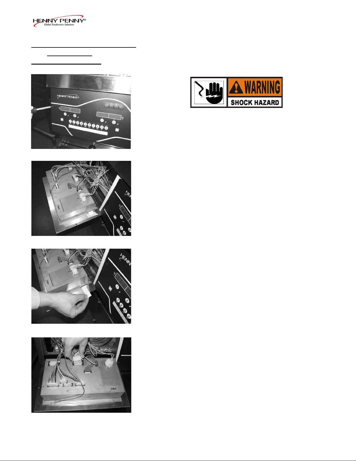
2. Remove the two screws securing the control panel.
3. Pull the top of the panel down, allowing the panel to be
supported by the 2 brackets in the slots in the control
shroud. (If changing control panel, continue onto step 5.)
4. If changing the menu card, loosen the tape securing the
menu card at the bottom, side of the control panel and pull
menu card from panel. Carefully, slide changed menu card
back into slot in panel and secure with tape.
5. Unplug the connectors going to the control board.
6. Install a new control panel in reverse order.
6-2Nov. 2009
Page 41

Model EEG-142, 143, 144
6-5. HIGH TEMPERATURE
LIMIT CONTROL
This is a safety, manual reset control, which senses the temperature of the oil. If the oil temperature exceeds 425°F
(218°C), this switch opens and shuts off the heat to the vat and
“E-10” shows in the display. When the temperature of the oil
drops to a safe operation limit, manually reset the control by
pressing the red reset button.
The red reset button is located behind the doors, underneath the
controls; nd the appropriate high limit and press the red reset
button; if high limit does not reset, high limit must be replaced;
If high limit resets, the oil starts heating.
Checkout
Before replacing a high temperature limit control, check to see
that its circuit is closed.
The oil temperature must be below 380°F (193°C) to accurately perform this check.
1. Remove electrical power supplied to the fryer.
To avoid electrical shock or property damage, move the
power switch to OFF and disconnect main circuit breaker,
or unplug cord at wall receptacle.
2. Using a Phillip’s-head screwdriver, or cordless drill, loosen
the screw securing the top of the control panel and secure
control panel in the slots of the shroud.
3. Open the front door, and using a 3/8” socket or nut-driver,
remove the 2 nuts securing the high limit bracket to the unit.
4. Pull the high limit and bracket from inside of control panel and
remove the two screws securing the high limit to the bracket.
5. Pull the high limit from the bracket, pull back the cardboard
protector, and remove the two electrical wires from the highlimit control.
6. Manually reset the control, then check for continuity
between the two terminals after resetting the control. If
the circuit is open, replace the control, then continue with
this procedure. (If the circuit is closed, the high limit is not
defective. Reconnect the two electrical wires.)
6-3Nov. 2009
Page 42

Model EEG-142, 143, 144
6-5. HIGH TEMPERATURE
LIMIT CONTROL
(Continued)
Replacement
If the tube is broken or cracked, the control opens, shutting off
electrical power. The control cannot be reset.
1. Pull-out on the drain valve knob and drain the oil from the
vat.
2. Remove electrical power supplied to the fryer.
To avoid electrical shock or property damage, move the
power switch to OFF and disconnect main circuit breaker,
or unplug cord at wall receptacle.
3. Using a 3/8” socket, remove the 2 screws securing the
burner jet bracket and remove bracket.
4. Pull both burner jets from unit.
5. Using a 5/16” wrench, loosen small inside screw nut on
capillary tube.
6. Using a Phillip’s-head screwdriver, remove the 2 screws the
capillary bulb bracket and pull bracket from unit.
7. Using an 11/16” crows-foot remove the large high limit tting
in vat wall, and pull the high limit from inside the control area.
6-4Nov. 2009
Page 43

Model EEG-142, 143, 144
6-5. HIGH TEMPERATURE
LIMIT CONTROL
(Continued)
6-6. MAIN POWER SWITCH
8. Using an 11/16” crows-foot remove the large high limit tting
in vat wall, and pull the high limit from inside the control area.
9. Install new high limit in reverse order and restore power to
unit.
10. 9.Fill vat by pressing and holding button until *FILTER* *MENU* shows in the display. Then once “1.EX-
PRESS FILTER” shows in the display, press ► 4 times
until “5.FILL FROM PAN” shows in the display. Press √
button and “PUMP” “EXIT” shows in the display. Press
√ button again, and oil lls vat. Once vat is full, press X
twice to return to normal operation.
This is a covered rocker switch, which in the ON position,
sends power to all the controls and lter motor.
To avoid electrical shock or property damage, move the
power switch to OFF and disconnect main circuit
breaker, or unplug cord at wall receptacle.
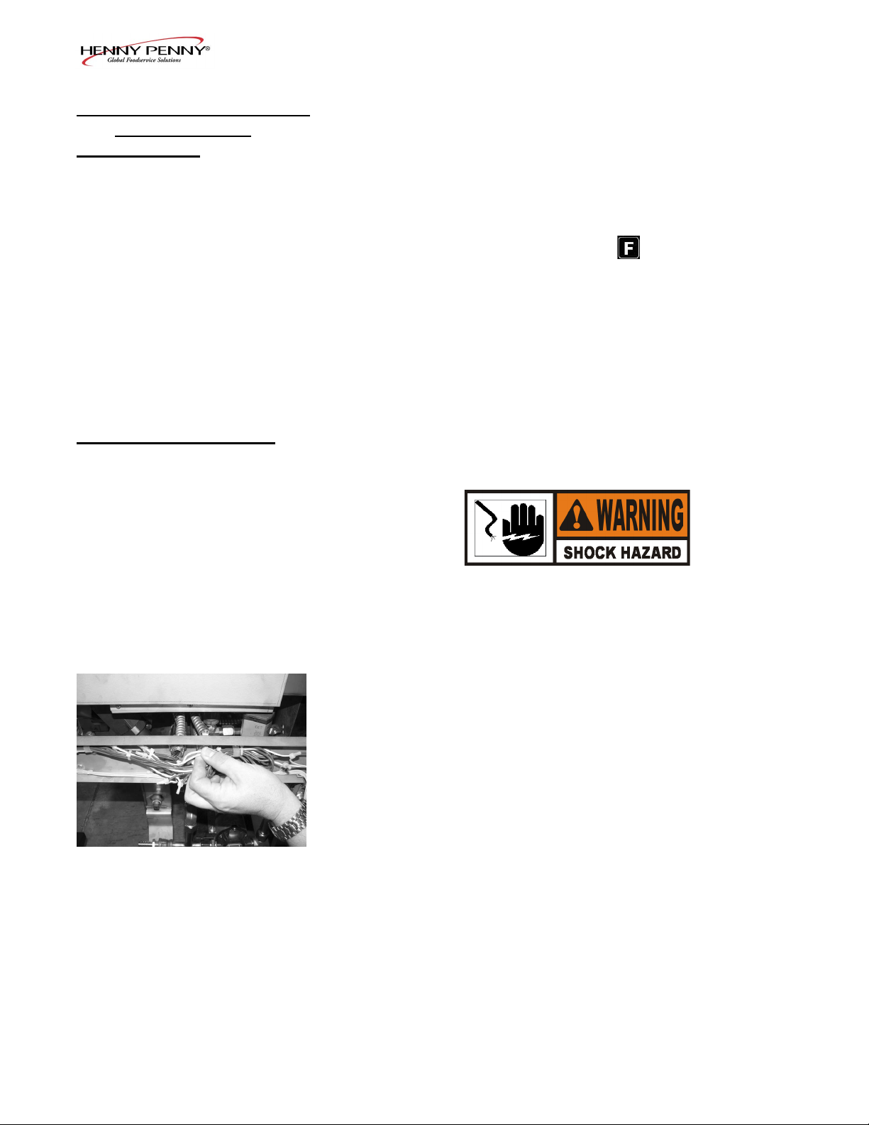
1. Remove right side panel.
2. Label and remove wires from the switch.
3. From the inside of the control area, squeeze in on the tabs
on the back of the switch and push the switch out the front
of the control area.
Checkout
4. Check across the two sets of terminals of the switch for
continuity. With the switch in the ON position, the circuit
should be closed. With the switch in the OFF position, the
circuit should be open.
If the switch is found to be defective, replace it by connecting
the wires to it (as labeled) and push new switch into place.
6-5Nov. 2009
Page 44

Model EEG-142, 143, 144
6-7. PROBE REPLACEMENT
Oil
level
probe
Temperature
probe
Oil
level
probe
The temperature probe is the center probe inside the vat (see
photo at left) and it relays the actual oil temperature to the control. If it becomes disabled, “E-6A or B” shows in the display.
The oil level probes (left & right-see photo at left) monitor the
oil level by temperature differences. If they becomes disabled,
the display shows: “E-18A”= left probe; “E18-B”= right probe;
“E18C”= both.
Also, if any of the probes are out of calibration more than 5°F,
or 5°C, the probe should be replaced. An Ohm check can be
performed also. See chart below.
Checkout:
To avoid electrical shock or property damage, move the
power switch to OFF and disconnect main circuit
breaker, or unplug cord at wall receptacle.
1. Using a Phillip’s-head screwdriver, or cordless drill, loosen
the screw securing the top of the control panel and secure
control panel in the slots of the shroud.
2. Pull the probe connector from the control panel and locate the
terminals in the connector for the probe being tested. Attach
meter leads onto those terminals and refer to the chart at left
to determine if probe is good or not. (Probe wires are labeled,
with #1 being the far left probe.)
6-6Nov. 2009
Page 45

Model EEG-142, 143, 144
6-7. TEMPERATURE PROBE
REPLACEMENT
(Continued)
Replacement:
1. Pull-out on the drain valve knob and drain the oil from the
vat.
To avoid electrical shock or property damage, move the
power switch to OFF and disconnect main circuit
breaker, or unplug cord at wall receptacle.
2. Using a 3/8” socket, remove the 2 screws securing the
burner jet bracket and remove bracket.
3. Pull both burner jets from unit.
4. Using a 1/2” wrench, remove the nut on the compression
tting, and remove the temperature probe from the vat.
5. Using a terminal extractor, remove the probe terminals from
the connector and pull remove probe from unit
6-7Nov. 2009
Page 46

Model EEG-142, 143, 144
6-7. TEMPERATURE PROBE
REPLACEMENT
(Continued)
6. Place the nut and new ferrule on the new temperature probe
and insert the temperature probe into the compression tting.
See drawing below.
7. Using the probe gauge in the kit, follow the instructions on
drawing below.
8. Hand-tighten compression nut and then a half turn with
wrench.
Excess force will damage temperature probe.
6-8Nov. 2009
Page 47
Model EEG-142, 143, 144
6-7. TEMPERATURE PROBE
REPLACEMENT
(Continued)
6-8. SOLENOID VALVES
9. Connect new temperature probe to the connector and fasten
connector onto control panel.
10. Replace control panel and reconnect power to vat.
11. Fill vat by pressing and holding button until *FILTER* *MENU* shows in the display. Then once “1.EX-
PRESS FILTER” shows in the display, press ►4 times until
“5.FILL FROM PAN” shows in the display. Press √ button
and “PUMP” “EXIT” shows in the display. Press √ button
again, and oil lls vat. Once vat is full, press X twice to
return to normal operation.
Each vat has a solenoid plumbed-into the oil return lines. They
are normally closed, but open when power is supplied, such as,
the controls are lling the vats.
To avoid electrical shock or property damage, move the
power switch to OFF and disconnect main circuit
breaker, or unplug cord at wall receptacle.
1. Remove both top and bottom rear panels, or a side panel,
depending upon the location of the solenoid.
Checkout
2. Follow the wires from the solenoid and through the conduit
and then cut the wires. Strip the wires back and take an
ohm reading:
120 Volts - 60Hertz 50 Ohms
220-240 Volts -50/60 Hertz 230 Ohms
6-9Nov. 2009
Page 48

6-8. SOLENOID VALVES
(Continued)
Model EEG-142, 143, 144
Replacement:
1. Using a 1 in. wrench, loosen the front and rear ttings to
solenoid.
2. Remove the conduit from the fryer and pull the solenoid
assembly from the fryer.
3. Remove the conduit from the solenoid.
6-10Nov. 2009
Page 49

Model EEG-142, 143, 144
6-8. SOLENOID VALVES
(Continued)
6-9. OIL CHANNEL
CLEAN-OUT
4. Remove elbow and ttings from solenoid stem assembly
and attach them to the new solenoid, using pipe sealent on
the threads.
5. Reattach the conduit to the new solenoid, threading the
wires through the conduit.
6. Reattach the solenoid assembly to the fryer.
7. Reattach the conduit to the fryer and connect the wires to
the fryer using wire nuts.
8. Replace rear side panels or rear panels and reconnect power
to the fryer.
Should the drain channel, under the vats, become clogged, access
to a clean-out plug is available on both right and left sides of the
unit.
6-11Nov. 2009
Page 50

Model EEG-142, 143, 144
6-10. FILTER PUMP & MOTOR
The 2 most common causes for a fryer not to pump oil are that
the pump is clogged, or the thermal overload switch has been
tripped on the motor. The pump and motor is located on the
rear of the fryer.
To reset the thermal overload switch:
1. Remove the right side panel and locate the pump and motor
in the rear of the fryer. If the motor is hot, allow it to cool
for about 5 minutes.
2. Since it takes some effort to reset the switch, use a tool,
such as a Phillip’s-head screwdriver, to press against the
reset button until a “click” is heard.
To remove debris from pump:
1. Loosen the four Allen head screws on the end of pump and
remove the cover. (Removing the bottom rear panel may
help in accessing the set screws.)
2. The inside is now exposed leaving a rotor and ve teon
rollers. Clean the rotor and rollers.
3. To reassemble, place rotor on drive shaft, and place roller
into rotor.
A small amount of grease might be needed to hold the
bottom roller into place until cover plate is put on. Make
sure O-ring is in proper position on plate.
Indicators, on the side of the two halves of the pump, must
allign together.
6-12Nov. 2009
Page 51

6-10. FILTER PUMP & MOTOR
(Continued)
Model EEG-142, 143, 144
To avoid electrical shock or property damage, move the
power switch to OFF and disconnect main circuit
breaker, or unplug cord at wall receptacle.
Removal:
1. Remove the bottom, rear panel and the right side panel.
2. Using a 5/8” wrench, loosen the front, exible line tting,
on the pump.
3. Using a 1” wrench, loosen the rear pump tting.
4. Locate the appropriate conduit on the right side of the unti
and disconnect the conduit from the fryer.
5. Using a 1/2 in. wrench, remove the 4 bolts securing the
motor to the motor bracket and pull the pump and motor
assembly from fryer.
To replace pump on motor:
1. Using a 1/2 in. wrench, remove the 2 bolts securing the
pump to the motor and pull the pump from the motor.
2. Install a new seal kit (part no. 17476) onto shaft of motor.
3. Allign the shaft of the motor with the rotor on the inside of
the pump and push pump onto shaft of motor.
4. Secure the pump onto the motor with the 2 bolts.
6-13Nov. 2009
Page 52

Model EEG-142, 143, 144
6-11. JIB PUMP
This pump keeps the vats lled and is used in the Automatic
Intermittant Filter process.
Replacement
To avoid electrical shock or property damage, move the
power switch to OFF and disconnect main circuit breaker,
or unplug cord at wall receptacle.
1. Remove the right side panel.
2. Using a 1” wrench, loosen both tting on each side of the
pump.
3. Using a Phillip’s-head screwdriver, remove the 4 screws
securing the bottom of pump.
4. Disconnect the wires in the rear of the pump and pull assembly from fryer.
6-12. EXPRESS FILTER PC
BOARD
5. Pull ttings from faulty pump and attach the ttings to the
new pump, in the same orientation.
6. Install new pump assembly in fryer, in reverse order and
then reconnect power to fryer.
This electronic board controls the Automatic Intermittant Filtering process.
Replacement
To avoid electrical shock or property damage, move the
power switch to OFF and disconnect main circuit
breaker, or unplug cord at wall receptacle.
1. Remove the left side panel.
2. Using a 3/8” socket or nut driver, remove the nuts securing
the cover and remove cover.
3. Pull connectors from PC board.
4. Using a 5/16” socket, remove the 6 nuts securing the board
and remove it from the fryer.
5. Install in reverse order. The control connectors are coloredcoded; Left-Red; Middle-White; Right-Blue.
6-14Nov. 2009
Page 53

Model EEG-142, 143, 144
6-13. TRANSFORMERS
AIF Transformer
Control Transformer Connector
These components drop the line voltage to low voltage compoents such as, control board, AIF board and gas valves.
Replacement
To avoid electrical shock or property damage, move the
power switch to OFF and disconnect main circuit
breaker, or unplug cord at wall receptacle.
1. Pull-down the control panel to access the desired transformer.
2. Label and remove wires from (AIF) transformer, or disconnect the white connector on the control transformer.
Control Transformer
AIF Transformer
3. Using a 5/16” socket, remove the nuts securing the transformer and pull the transformer from unit.
4. Replace transformer in reverse order.
6-15Nov. 2009
Page 54

Model EEG-142, 143, 144
6-14. FILTER MOTOR RELAY
This component is located behind the left control panel and
regulates voltage to the lter motor.
Replacement
To avoid electrical shock or property damage, move the
power switch to OFF and disconnect main circuit breaker,
or unplug cord at wall receptacle.
1. Remove left side panel.
2. Label and remove wires from relay.
3. Using a 5/16” wrench, remove the nuts securing the relay
and remove relay from fryer.
4. Install new relay in reverse order.
6-15. GAS CONTROL VALVES
The gas control valve assembly controls the ow of gas to the
pilot and the main burner. The valve has two 24 volt coils,
which are regulated by terminals PV and MV on the valve. For
gas ow to the pilot, 24 VAC must be present between the PV
and COM terminals.For gas ow to the main burner, 24 VAC
must be present between the MV and COM terminals.
TO AVOID INJURY, PROPERTY DAMAGE, OR
EXPLOSION, BEFORE REPLACING STARTING THIS
PROCEDURE, DO THE FOLLOWING:
• MOVE THE POWER/PUMP SWITCH TO THE
“OFF”POSITION.
• DISCONNECT THE MAIN CIRCUIT BREAKER
AT THE WALL, OR UNPLUG THE POWER CORD.
• TURN OFF THE MAIN GAS SUPPLY TO THE FRYER AND DISCONNECT AND CAP THE SUPPLY
LINE TO FRYER.
6-16Nov. 2009
Page 55

Model EEG-142, 143, 144
6-15. GAS CONTROL VALVES
(Control)
Replacement:
1. Remove the appropriate side panel and/or open the doors.
2. Label and remove wires from gas valve.
3. Using a 5/8” wrench, loosen the exible gas line tting.
4. Using a 1” wrench, loosen the rear tting and pull assembly
from the unit.
5. Pull ttings from gas valve and attach the ttings to the
new gas valve, in the same orientation.
6. Install new gas valve in reverse order.
6-17Nov. 2009
Page 56

Model EEG-142, 143, 144
6-16. BLOWER MOTORS
The blower motor assembly creates the draft for the burners. If
the blower motor fails, the air switch fails to close, causing an
“E-20B” error code in the display.
Replacement
To avoid electrical shock or property damage, move the
power switch to OFF and disconnect main circuit breaker,
or unplug cord at wall receptacle.
1. Remove the bottom, rear panel.
2. Using a 3/8” socket or nut driver, remove the nuts securing
the blower brackets to the fryer.
3. Remove the brackets from the blower.
4. Remove the pressure tube from the blower.
5. Locate and cut wires and remove blower from unit.
6. Connect the new blower motor wires to the fryer using wire
nuts, and install the new blower motor in reverse order as
above.
Before installing the bottom, rear cover, clean the blower in-
take slots to ensure sufcient air ow to the blowers.
6-18Nov. 2009
Page 57
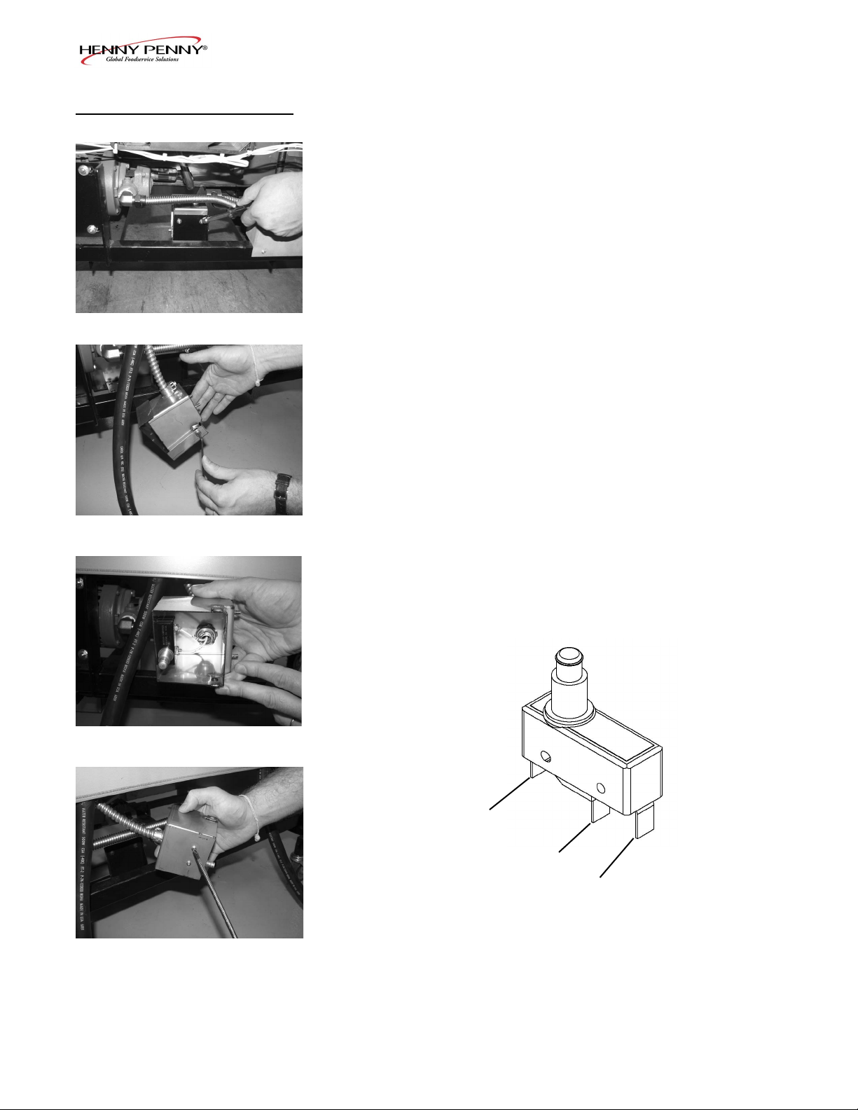
Model EEG-142, 143, 144
6-17. DRAIN PAN SWITCH
This switch closes when the drain pan is pushed properly in
place under the fryer. If the drain pan is not properly in place,
or the drain switch is faulty, display prompts such as, “CHECK
PAN”; “FILTER PAN MISSING”; “CHANGE FILTER PAD”
shows in the display.
Removal:
1. Drain pan switch is located on the rear of the fryer. Using
a 3/8” socket or nut driver, remove the nuts securing the
drain switch bracket to the fryer.
2. Using a 1/8” Allen wrench, remove the shoulder bolt securing the cover and remove cover.
3. Using a Phillips-Head screwdriver, remove the screws
securing the switch to the bracket and remove switch from
bracket.
4. Label and remove wires from switch
Checkout:
5. Check for continuity across the normally open and the
common terminals of the drain switch. The circuit should
show open and when the plunger is pressed, show closed.
Replace switch if faulty, placing wires on new switch on
the normally open and common terminals.
Normally
Closed
6-19Nov. 2009
Normally
Open
Common
Page 58

Model EEG-142, 143, 144
6-18. FILTER BEACON™
Replacement
To avoid electrical shock or property damage, move the
power switch to OFF and disconnect main circuit breaker,
or unplug cord at wall receptacle.
1. Remove right or left side panel for end vats, or hinge-down
the control panel for center vats.
2. Pull apart the light by pulling on the rear of the light and removing the front part of the light from the front of the fryer.
3. Locate and cut the light wires and pull the light from unit.
4. Connect new light wires, using wirenuts and install light in
reverse order.
5. Restore power to the unit.
6-20Nov. 2009
Page 59

Model EEG-142, 143, 144
6-19. AIR PRESSURE
SWITCHES
The vacuum switch senses the ow of air coming from the
blower. If the airow is reduced below a set amount, the switch
cuts power to the control valve, which shuts the burners down.
Replacement:
To avoid electrical shock or property damage, move the
power switch to OFF and disconnect main circuit breaker,
or unplug cord at wall receptacle.
1. Air switches are located on the rear of the fryer. Using a
Phillip’s-Head screwdriver, remove the 2 screws securing
the outer cover and remove cover.
2. Label and pull wires from switch.
3. Pull tube from switch and using a Phillip’s-Head screwdriver, remove the 2 screws securing the switch to the
bracket and remove switch.
4. Install new switch in reverse order and restore power to
unit.
6-21Nov. 2009
Page 60

Model EEG-142, 143, 144
6.20. IGNITOR & FLAME
SENSOR ASSEMBLY
The ame sensor should glow a bright red when the pilot is lit
and allows the gas control valve to open. If it does not sense a
ame, it shuts off the gas control valve.
Flame Sensor Replacement:
1. Remove control panel.
2. Pull wire from ame sensor.
3. Using a 7/16” wrench, remove the nut securing the ame
senor and pull the sensor from the unit.
4. Install new ame sensor in reverse order.
Ignitor Replacement:
TO AVOID INJURY, PROPERTY DAMAGE, OR EXPLOSION, BEFORE STARTING THIS PROCEDURE, DO
THE FOLLOWING:
• MOVE THE POWER/PUMP SWITCH TO THE
“OFF” POSITION.
• DISCONNECT THE MAIN CIRCUIT BREAKER AT
THE WALL, OR UNPLUG THE POWER CORD.
• TURN OFF THE MAIN GAS SUPPLY TO THE FRYER AND DISCONNECT AND CAP THE SUPPLY
LINE TO FRYER.
1. Follow steps 1 to 3 above.
2. Using a 7/16” wrench, loosen the pilot, gas line tting.
3. Using a small Phillip’s-Head remove the 2 screws securing
the ignitor assembly.
4. Pull wire from ignition module and remove ignitor assembly from unit.
5. Install new ignitor assembly in reverse order.
6-22Nov. 2009
Page 61

Model EEG-142, 143, 144
6-21. IGNITION MODULES
During normal operation, the ignition modules send 24 volts to
the ignitors and gas control valve. If a module does not sense
a pilot ame, the module starts the ignition process again. But,
if a pilot light goes out for longer that 15 seconds, or it goes out
3 times within 15 seconds, the module keeps the 24 volts from
reaching the gas control valve. The burners shut down.
Replacement:
To avoid electrical shock or property damage, move the
power switch to OFF and disconnect main circuit breaker,
or unplug cord at wall receptacle.
1. Open the left door and using a Phillip’s-Head screwdriver,
remove the screws securing the module cover and remove
cover.
2. Label and pull the wires from the module.
3. Using a 3/8” socket or nut driver remove the nuts securing
the module and remove module from unit.
4. Install new module in reverse order and restore power to
the unit.
6-23Nov. 2009
Page 62

Model EEG-142, 143, 144
6-22. PRESSURE
TRANSDUCER
Expansion Chamber
This component controls the AIF lter pump by sensing the
pressure in the expansion chamber.
Voltage range is 0.5 to 4.5 VDC, corresponding to a pressure
range of 0 to 30 PSIG
A messured pressure below -1.5 PSI or above 32 PSI may
indicate a failed transducer, it has become disconnected, or a
clogged expansion chamber.
To view the the pressure, press ◄ ► at the same time and
“*INFO* *MODE*” shows in the display, followed by
“1. E-LOG”. Press ► until “15. AIF” shows in the display.
Press ▼ until “PRESSURE SENSOR” shows in the left dis-
play. Press X button to show pressure in PSI.
An over-pressure issue can also indicate a return valve failing
to open, instead of a faulty transducer or a clogged chamber.
In case of a clogged expansion chamber, remove the cleanout plugs at each end of the chamber to clean the obstructions
inside the chamber. Photo at left.
Clean-out Plugs
Extra long ll times or oil bubbling at the end of an AIF cycle
may be signs of a clogged expansion chamber or faulty transducer.
Replacement:
To avoid electrical shock or property damage, move the
power switch to OFF and disconnect main circuit
breaker, or unplug cord at wall receptacle.
1. Remove the left side panel.
2. Pull-out on the clip, while pushing up on the wire harness
connector, at the top of the tranducer, to remove wires.
3. Using a 1-1/16” wrench, remove the tranducer from the
expansion chamber.
4. Using pipe thread sealant, install new tranducer in reverse
order and restore power to the unit.
6-24Nov. 2009
Page 63

Model EEG-142, 143, 144
83289 - 1 & 2 WELL - FULL VAT (3 & 4 WELL SEE NEXT PAGE)
6-25Nov. 2009
Page 64

Model EEG-142, 143, 144
77318 - 3 & 4 WELL - FULL VAT (1 & 2 WELL SEE PREVIOUS PAGE)
6-26Nov. 2009
Page 65

Model EEG-142, 143, 144
84138 - 1 & 2 WELL - FS (3 & 4 WELL SEE NEXT PAGE)
6-27Nov. 2009
Page 66

Model EEG-142, 143, 144
84138 - 1 & 2 WELL - FSS/FSSS (1 & 2 WELL SEE PREVIOUS PAGE)
6-28Nov. 2009
Page 67

Model EEG-142, 143, 144
84248 - 1 & 2 WELL - SPLIT VAT (3 & 4 WELL SEE NEXT PAGE)
6-29Nov. 2009
Page 68

Model EEG-142, 143, 144
84248 - 3 & 4 WELL - SPLIT VAT (1 & 2 WELL SEE PREVIOUS PAGE)
6-30Nov. 2009
Page 69

Model EEG-142, 143, 144
6-31Nov. 2009
Page 70

SECTION 7. PARTS INFORMATION
Model EEG-142, 143, 144
7-1. INTRODUCTION
7-2. GENUINE PARTS
7-3. WHEN ORDERING
PARTS
This section lists the replaceable parts of the Henny Penny Model EEG
fryer.
Use only genuine Henny Penny parts in your fryer. Using a part of lesser
quality or substitute design may result in damage to the unit or personal
injury.
Once the parts that you want to order have been found in the parts list, write
down the following information:
Example:
Item Number 2
Part Number 60241
Description High Limit
From the data plate, list the following information:
Example:
7-4. PRICES
7-5. DELIVERY
7-6. WARRANTY
7-7. RECOMMENDED
SPARE PARTS FOR
DISTRIBUTORS
Product Number 01100
Serial Number0 001
Voltage 208
Your distributor has a price parts list and will be glad to inform you of the
cost of your parts order.
Commonly replaced items are stocked by your distributor and will be
sent out when your order is received. Other parts will be ordered, by your
distributor, from Henny Penny Corporation. Normally, these will be sent to
your distributor within three working days.
All replacement parts (except lamps and fuses) are warranted for 90 days
against manufacturing defects and workmanship. If damage occurs during
shipping, notify the carrier at once so that a claim may be properly led.
Refer to warranty in the front of this manual for other rights and limitations.
Recommended replacement parts, stocked by your distributor, are indicated
with √ in the parts lists. Please use care when ordering recommended parts,
because all voltages and variations are marked. Distributors should order
parts based upon common voltages and equipment sold in their territory.
7-1Nov. 2009
Page 71
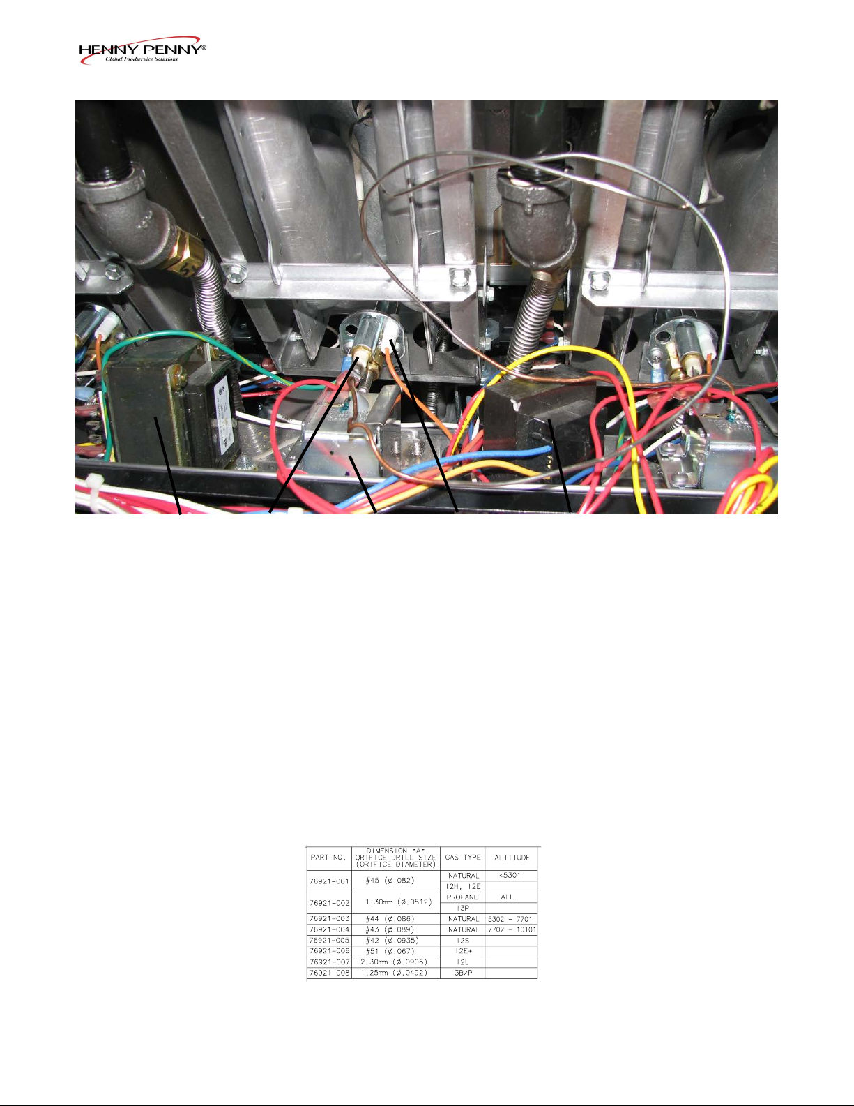
Model EEG-142, 143, 144
1
2
3 4 5
Item No. Part No. Description Quantity
√ 1 TS22-012 TRANSFORMER - AIF .................................................. 1
√ 2 76978 FLAME SENSOR ............................................................ 1/vat
√ 3 16738 HIGH LIMIT - 450
o
F ....................................................... 1/vat
√ 4 75854 ASSY - SPARK IGNITOR (PILOT) ............................... 1/vat
√ 5 84391 TRANSFORMER - 120 VOLT ....................................... 1/vat
√ 5 80375 TRANSFORMER - 230 VOLT ....................................... 1/vat
6 76921 ORIFICE - BRASS (See chart below) ............................. 4/VAT
√ recommended parts
7-2Nov. 2009
Page 72

Model EEG-142, 143, 144
1
Item No. Part No. Description Quantity
1 77679 CASTER - 4” ................................................................... 2
√ 2 78118 VALVE - GAS CONTROL - NAT ................................... 1/vat
√ 2 78517 VALVE - GAS CONTROL - LP ...................................... 1/vat
√ 3 73647 SOLENOID - ASCO - 120V (JIB Solenoids) .................. 2
√ 3 74582 SOLENOID - ASCO - 230V (JIB Solenoids) .................. 2
√ 4 73473 PUMP - OIL TOP OFF - 120V ........................................ 1
√ 4 74583 PUMP - OIL TOP OFF - 230V ........................................ 1
5 77575 CASTER - 4” - W/BRAKE ............................................. 2
√ recommended parts
2 3
4 5
7-3Nov. 2009
Page 73

NON-CE GAS VALVE ASSEMBLY
Model EEG-142, 143, 144
CE GAS VALVE ASSEMBLY
Item No. Part No. Description Quantity (per assy)
1 16807 FITTING - MALE CONNECTOR .................................. 1
√ 2 78118 VALVE - GAS CONTROL - NAT ................................... 1
√ 2 78517 VALVE - GAS CONTROL - LP ...................................... 1
3 FP01-211 CONNECTOR - MALE 1/2 TUBE TO 1/2 NPT ............ 1
4 16239 ELBOW - STREET - 90 DEGREES ............................... 1
5 FP05-004 ELBOW - 1/4 TUBE TO 1/8 PIPE Z ............................... 2
6 FP01-028 NIPPLE - CLOSE 1/2 NPT SS 1 LG ............................... 1
√ 7 34802 VALVE - SOLENOID GAS - 24V - 50/60 HZ ................ 2
7-4Nov. 2009
Page 74

Model EEG-142, 143, 144
1
Item No. Part No. Description Quantity
√ 1 84454RB PC BOARD - AIF FILTER ..................................................... 1
√ 2 79213 TRANSDUCER - PRESSUER 30 PSI ................................... 1
√ 3 ME90-008 RELAY - PUMP MOTOR - 12 VDC - 30 AMP ..................... 1
4 84384 HARNESS - PRESSURE TRANSDUCER ........................... 1
5 51065 ASSY-EMC FILTER BOARD (not shown) ............................ 1
6 80373 BLOCK -TERMINAL POWER - CE (not shown) ................. 1
√ recommended parts
2
3
7-5Oct. 2012
4
Page 75

Model EEG-142, 143, 144
1
2
3 4 65
8
11
9
10
1
12
13
7
7-6Nov. 2009
Page 76

Model EEG-142, 143, 144
Item No. Part No. Description Quantity
√ 1 77992 SWITCH - PRESSURE - 0.80 (behind covers)...................... 1/vat
√ 2 77826-001 MOTOR - BLOWER - 230V .................................................. 1/full; 1/split
√ 2 77826-002 MOTOR - BLOWER - 120V .................................................. 1/full; 1/split
3 67589 PUMP & MOTOR ASSY...(See page 8-18 for details) .......... 1
√ 67583 MOTOR - 1/2 HORSE ..................................................... 1
17437 PUMP - FILTER .............................................................. 1
17476 SEAL KIT ........................................................................ 1
√ 4 74469 VALVE - CHECK - 1/2” (Vat Fill) ......................................... 1/vat
√ 5 73647 SOLENOID - ASCO - 120V (return valves) .......................... 1/vat
√ 5 74582 SOLENOID - ASCO - 230V (return valves) .......................... 1/vat
140229 ---KIT- SOLENOID REPAIR ................................................. A/R
6 73517 ASSY - POWER CORD 120V ............................................... 1
7 79443 TUBE - PRESSURE SWITCH (see chart below) .................. AR
8 80154 WELD ASSY - SWITCH HSG W/BOOT .............................. 1
9 SC06-070 SCREW - 1/4 DIA X 1/8 L SHLDR SS ................................. 2
10 80156 COVER - SWITCH HOUSING W/BOOT ............................ 1
11 NS02-005 NUT - HEX KEPS #6-32 C .................................................... 2
√ 12 80148 ASSY-DRAIN SWITCH W/BOOT ....................................... 1
13 SC01-058 SCREW - #6-32 X 1 PH PHD C ............................................ 2
√ 14 MS01-572* PRIMER - LOCTITE - .8 OZ. CAN
(for check valve threads) . 1
√ 15* 76095 VALVE-DRAIN ORING SEAL ............................................. A/R
16 50764 MICROSWITCH-RIGID LEVER.......................................... A/R
√ recommended parts
*not shown
7-7Feb. 2013
Page 77

Model EEG-142, 143, 144
1
2
3
11
10
9
8
7
4
5 6
Item No. Part No. Description Quantity
√ 1 81980 LED - 5 mm BLUE .......................................................... 1/vat
2 16101 KNOB - SPINDLE - BLACK.......................................... 1/vat
3 76930 PANEL-LH SIDE ............................................................ 1
4 81185 ASSY-LH DOOR ............................................................ 1
4 81847 ASSY-LH DOOR - EEG-144 ONLY ............................... 1
√ 5 77839 MODULES - IGNITION ................................................. 1/vat
6 81190 ASSY - RH DOOR .......................................................... 1 or 2
√ 7 52224 SWITCH - POWER ......................................................... 1
8 76931 PANEL-RH SIDE ............................................................ 1
√ 9 81943RB ASSY - CONTROL - EEX .............................................. A/R
9 84417RB ASSY-EVOLUTION ELITE AUTO CONT .................... A/R
10 03647 COVER - SPLIT VAT ...................................................... 1/vat
10 03646 COVER - FULL VAT ....................................................... 1/vat
11 77842 HANGER-BASKET - EEG-142 ...................................... 1
11 77709 HANGER-BASKET - EEG-143 ...................................... 1
11 77934 HANGER-BASKET - EEG-144 ...................................... 1
√ recommended parts
7-8March 2014
Page 78

Models
Full & Split
Vats:
EEg-141, 142,
143 & 144
74626
17255
NS03-103
Pivot Stop Drain Handle
Kit / Part Numbers
81753
17255
NS03-103
SN: BW1201006 &
After (Jan. 23, 2012)
Model EEG-142, 143, 144
140175 140176
Before SN:
BW1201006
7-9April 2014
Page 79

Model EEG-142, 143, 144
1
Item No. Part No. Description Quantity
√ 1 76980 RACK - SPLIT VAT ........................................................ 1/vat
√ 1 76982 RACK - FULL VAT ......................................................... 1/vat
2 77061 GUARD - HIGH LIMIT ................................................. 1/vat
√ 3 14974 PROBE - LEVEL SENSE - 2.5 in. ................................. 2/vat
√ 4
14974 PROBE - TEMPERATURE - 2.5 in. ............................... 1/vat
32
4
√ recommended parts
7-10Nov. 2009
Page 80

Model EEG-142, 143, 144
1 2
Item No. Part No. Description Quantity
1 03617 ACCESSORY-JUG-AUTO TOP OFF (EMPTY) ........... 1
2 78992 ASSY-JIB TUBE & QUICK DISC .................................. 1
2 80490 ASSY-INT’L. JIB TUBE & QUICK DISC ..................... 1
√ MS01-561 O-RING - JIB TUBE (not shown) ............................. 1
√ 3 77288 ASSY - HOSE .................................................................. 1
4 77630 WELD ASSY - JIB SHELF ............................................. 1
3 4
√ recommended parts
7-11Nov. 2009
Page 81

Model EEG-142, 143, 144
1 2
Item No. Part No. Description Quantity
1 78305 COVER - REAR SHROUD - EEG-142 .......................... 1
1 77664 COVER - REAR SHROUD - EEG-143 .......................... 1
1 79565 COVER - REAR SHROUD - EEG-144 .......................... 1
2 83700 COVER - REAR - LOWER - EEG-142 ......................... 1
2 84161 COVER - REAR - LOWER - EEG-143 ......................... 1
2 84162 COVER - REAR - LOWER - EEG-144 ......................... 1
7-12Nov. 2009
Page 82

Model EEG-142, 143, 144
4
3
5
1
2
6
Item No. Part No. Description Quantity
√ 1 81943RB ASSY - EEE14X CONTROL............................................ *
√ 2 81354 DECAL - EVOLUTION ELITE CONTROL .................. 1/control
3 NS02-005 NUT - HEX KEPS #6-32 C ....................................... 23/control
√ 4 26974 ASSY - SPEAKER .................................................... 1/control
5 82085 STUD ASSY - CONTROL PANEL COVER .................. 1/control
6 81612 MENU CARD - EVOLUTION ....................................... 1/control
6 81613 MENU CARD - BLANK - EVOLUTIO ......................... 1/control
7 MS01-571 TOOL - TERMINAL EXTRACTOR (not shown) .......... 1
*EEG142=2; EEG143=3; EEG144=4
√ recommended parts
7-13Nov. 2009
Page 83

Model EEG-142, 143, 144
2
3
13
12
11
9
8
7
4
10
5
6
Item No. Part No. Description Quantity
1 78456 ASSY - DRAIN PAN ...................................................... 1
2 82674 ASSY-DRAIN PAN COVER ..................................... 1
3 76259 WELD ASSY-CRUMB CATCHER .......................... 1
4 76179 WELD ASSY-FILTER WEIGHT .............................. 1
5 76375 FILTER-SECTION .................................................... 1
6 82672 WELD ASSY-DRAIN PAN (Less Cover) ................. 1
7 52487 CASTER - DRAIN PAN ...................................... 4
8 74573 ADAPTOR - PUMP TO PICKUP TUBE ............ 1
√ 9 74189 O-RING-PICKUP TUBE ..................................... 3
√ 10 *12074 SMART FILTERS (PAD) - 30 COUNT- ........................ 1
√ 10 *12076 SMART FILTERS (PAPER) ............................................ 1
√ 11 12126 BRUSH - BLACK L ........................................................ 1
√ 12 12112 BRUSH - STRAIGHT WHITE ....................................... 1
√ 13 12116 BRUSH - FRYER - LONG HANDLE ............................ 1
1
*12074- 11.25”X 19.125”
*12076- 25.5”X 16.5”
7-14July 2014
Page 84

Model EEG-142, 143, 144
Item No. Part No. Description Quantity
1 77523 TUBE-SUCTION 18 IN L DORMONT .......................... 1
2 FP01-206 CONNECTOR-3/8 NPT FEM 45 FLARE ..................... 1
3 77259 BRACKET-PLUG AND PLAY ....................................... 1
4 77248 ADAPTER-TUBE END .................................................. 1
5 FP01-204 NIPPLE-3/8 NPT X 6IN L BLACK ................................ 1
7-15Nov. 2009
Page 85

Model EEG-142, 143, 144
Filter Motor and Pump
Item No. Part No. Description Quantity
√ 1 67583 MOTOR, 1/2 HP - 50/60 Hz ............................................ 1
√ 2 17476 SEAL KIT ........................................................................ 1
3 17437 PUMP ASSEMBLY ......................................................... 1
√ 4 SC01-132 SCREW, Pump Cover ................................................ 1
√ 5 17451 COVER, Pump ........................................................... 1
√ 6 17447 ROTOR, Pump ........................................................... 1
√ 7 17446 ROLLER, Pump ......................................................... 5
√ 8 17453 O-RING ...................................................................... 1
√ 9 17454 BODY, Pump ............................................................. 1
√ 10 17456 SHIELD, Pump .......................................................... 2
√ 11 SC01-026 SCREW, Pump Shield ................................................ 1
7-16Nov. 2009
Page 86

Model EEG-142, 143, 144
AUTO-LIFT PARTS
2
3
7
5
4
6
1
8
Item No. Part No. Description Quantity/Vat
1 83982 ASSY - BREAKAWAY HINGE ............................................ 2/full; 1/split
2 84279 WELD ASSY - HINGED BASKET HANGER ............. 2/full; 1/split
3 15212 PLUG - TUBING SQUARE ............................................ 2/full; 1/split
4 83925 PIN - 1/4 x 2.25 HINGE .................................................. 2/full; 1/split
4* MS01-578 SHIM .............................................................................. 6/full; 3/split
5* SC01-267 SCREW - 1/4-28 x 1 HEX HD SS .................................. 2/full; 1/split
5* NS01-018 NUT ................................................................................. 2/full; 1/split
6 83680 WELD ASSY - BREAKAWAY HINGE ......................... 2/full; 1/split
B 7 85022 ASSY - EE AUTOLIFT ACTUATOR & CONNECTOR...... 2/full; 1/split
8 84470 WELD ASSY - AUTOLIFT REAR GUARD - 2 WELL ...... 1
8 84913 WELD ASSY - AUTOLIFT REAR GUARD - 3 WELL ...... 1
8 84918 WELD ASSY - AUTOLIFT REAR GUARD - 4 WELL ...... 1
9* 140273 EE-AUTOLIFT ACTUATOR MOTOR ................................ A/R
9* 140274 EE-AUTOLIFT ACTUATOR SWITCH................................ A/R
Recommend Parts: A=Truck Stock/B=Dist. Stock / *not shown
7-17Sept. 2013
 Loading...