

Page 1

Model BCC/BCR-140, BCC/BCR-175, BFR/BCR-350
Henny Penny
Blast Chiller/Freezer
Models BCC/BCR-140
Models BCC/BCR-175
Models BFR/BCR-350
OPERAT OR’S MANUAL
Page 2

Page 3

Model BCC/BCR-140, BCC/BCR-175, BFR/BCR-350
LIMITED WARRANTY FOR HENNY PENNY EQUIPMENT
Subject to the following conditions, Henny Penny Corporation makes the following limited warranties to the original
purchaser only for Henny Penny appliances and replacement parts:
NEW EQUIPMENT: Any part of a new appliance, except baskets, lamps, and fuses, which proves to be defective in
material or workmanship within two (2) years from date of original installation, will be repaired or replaced without
charge F .O.B. factory , Eaton, Ohio, or F .O.B. authorized distributor . Baskets will be repaired or replaced for ninety (90)
days from date of original installation. Lamps and fuses are not covered under this Limited W arranty. To validate this
warranty, the registration card for the appliance must be mailed to Henny Penny within ten (10) days after installation.
FILTER SYSTEM: Failure of any parts within a fryer filter system caused by the use of the non-OEM filters or
other unapproved filters is
REPLACEMENT PARTS: Any appliance replacement part, except lamps and fuses, which proves to be defective in
material or workmanship within ninety (90) days from date of original installation will be repaired or replaced without
charge F .O.B. factory , Eaton, Ohio, or F .O.B. authorized distributor .
The warranty for new equipment covers the repair or replacement of the defective part and includes labor charges and
maximum mileage charges of 200 miles round trip for a period of one (1) year from the date of original installation.
not covered under this Limited Warranty.
The warranty for replacement parts covers only the repair or replacement of the defective part and does not include any
labor charges for the removal and installation of any parts, travel, or other expenses incidental to the repair or replacement of
a part.
EXTENDED FRYPOT WARRANTY: Henny Penny will replace any frypot that fails due to manufacturing or workmanship
issues for a period of up to seven (7) years from date of manufacture. This warranty shall not cover any frypot that fails due to
any misuse or abuse, such as heating of the frypot without shortening.
0 TO 3 YEARS: During this time, any frypot that fails due to manufacturing or workmanship issues will
be replaced at no charge for parts, labor, or freight. Henny Penny will either install a new frypot at no cost or
provide a new or reconditioned replacement fryer at no cost.
3 TO 7 YEARS: During this time, any frypot that fails due to manufacturing or workmanship issues will
be replaced at no charge for the frypot only . Any freight charges and labor costs to install the new frypot as
well as the cost of any other parts replaced, such as insulation, thermal sensors, high limits, fittings, and
hardware, will be the responsibility of the owner.
Any claim must be presented to either Henny Penny or the distributor from whom the appliance was purchased. No
allowance will be granted for repairs made by anyone else without Henny Penny’s written consent. If damage occurs during
shipping, notify the sender at once so that a claim may be filed.
THE ABOVE LIMITED WARRANTY SETS FOR TH THE SOLE REMEDY AGAINST HENNY PENNY FOR ANY BREACH
OF W ARRANTY OR OTHER TERM. BUYER AGREES THA T NO OTHER REMEDY (INCLUDING CLAIMS FOR ANY INCIDENT AL OR CONSEQUENTIAL DAMAGES) SHALL BE AV AILABLE.
The above limited warranty does not apply (a) to damage resulting from accident, alteration, misuse, or abuse; (b) if the
equipment’s serial number is removed or defaced; or (c) for lamps and fuses. THE ABOVE LIMITED W ARRANTY IS EXPRESSL Y IN LIEU OF ALL OTHER W ARRANTIES, EXPRESS OR IMPLIED, INCLUDING MERCHANT ABILITY AND FITNESS, AND ALL OTHER WARRANTIES ARE EXCLUDED. HENNY PENNY NEITHER ASSUMES NOR AUTHORIZES ANY
PERSON TO ASSUME FOR IT ANY OTHER OBLIGA TION OR LIABILITY.
Revised 01/01/07
FM05-027-F
Revised 09-27-07
Page 4

Model BCC/BCR-140, BCC/BCR-175, BFR/BCR-350
T ABLE OF CONTENTS
Section Page
Section 1. INTRODUCTION ...................................................................................................................1-1
1-1. Blast Chiller/Freezer .................................................................................................... 1-1
1-2. Features ....................................................................................................................... 1-1
1-3. Proper Care ................................................................................................................. 1-1
1-4. Assistance.................................................................................................................... 1-1
1-5. Safety........................................................................................................................... 1-2
Section 2. INSTALLATION...................................................................................................................... 2-1
2-1. Introduction .................................................................................................................. 2-1
2-2. Unpacking ....................................................................................................................2-1
2-3. Electrical ...................................................................................................................... 2-2
2-4. Location ....................................................................................................................... 2-3
2-5. Refrigerant Information ............................................................................................... 2-6
2-6. Refrigeration Capacities .............................................................................................. 2 -6
2-7. BCC-175 Water Supply and Drain ..............................................................................2-6
2-8. De-Icing and Cleaning Water Drainage ...................................................................... 2-7
2-9. Remote Condensing Units Information........................................................................ 2-7
2-10. Operation Checklist......................................................................................................2-10
Section 3. OPERATION............................................................................................................................3-1
3-1. Introduction ..................................................................................................................3-1
3-2. Operating Controls .......................................................................................................3-1
3-3. Basic Operation ........................................................................................................... 3-4
3-4. De-Icing .......................................................................................................................3-7
3-5. Cleaning ....................................................................................................................... 3-8
3-6. Seasonal or Prolonged Shutdown.................................................................................3-9
3-7. Programming................................................................................................................3-10
Section 4. TROUBLESHOOTING...........................................................................................................4-1
4-1. Troubleshooting Guide ..................................................................................................4-1
4-2. Alarm Messages.......................................................................................................... 4-2
GLOSSARY .............................................................................................................................G-1
Distributor Lists - Domestic and International
i 605
Page 5

Model BCC/BCR-140, BCC/BCR-175, BFR/BCR-350
SECTION 1. INTRODUCTION
1-1. BLAST CHILLER/ The Henny Penny Blast Chillers are designed to carry out fast
FREEZER refrigeration of food products. The units are electronically con-
trolled for easy use and for consistent operation. The
BCC/BCR-140 chills up to 140 lbs (65 kg) of product, the
BCC/BCR-175 chills up to 175 lbs (80 kg), and the BCR-350
chills up to 350 lbs (160 kg) of product. The BFR-350 chills
and freezes up to 350 lbs. (160 kg) of product.
1-2. FEA TURES • Interior and exterior made of 304 stainless steel
• Electronic controls with self diagnostics
• Manual de-icing of the interior by electrical heater
• Multi-sensored Frigiprobe food probe
• Easily maintained
• The BCC-140 and BCC-175 have water cooled
condensing units
• The BCR-140, BCR-175, and BCR-350 are shipped
without condensing units
• HACCP printer capabilities
• The BFR/BCR-350 can use the combi MOR-215 & 220
and OPR-215 & 220
• An auto backup cycle in case of an air temperature probe
failure
As of August 16, 2005, the W aste Electrical and Electronic
Equipment directive went into effect for the European Union.
Our products have been evaluated to the WEEE directive.
W e have also reviewed our products to determine if they
comply with the Restriction of Hazardous Substances directive
(RoHS) and have redesigned our products as needed in order
to comply . T o continue compliance with these directives, this
unit must not be disposed as unsorted municipal waste. For
proper disposal, please contact your nearest Henny Penny
distributor.
1-3. PROPER CARE As in any unit of food service equipment, the Henny Penny blast
chillers do require care and maintenance. Requirements for the
maintenance and cleaning are contained in this manual and must
become a regular part of the operation of the unit at all times.
1-4. ASSISTANCE Should you require outside assistance, just call your local indepen-
dent Henny Penny distributor in your area, call Henny Penny
Corp.at 1-800-417-8405 toll free or 1-937-456-8405, or visit
Henny Penny online at www .hennypenny.com.
907 1-1
Page 6

Model BCC/BCR-140, BCC/BCR-175, BFR/BCR-350
1-5. SAFETY The Henny Penny Blast Chiller/Freezer has safety features
incorporated. However, to ensure a safe operation, read
and fully understand the proper installation, operation, and
maintenance procedures. The instructions in this manual
have been prepared to aid you in learning the proper procedures. Where information is of particular importance or
safety related, the words NOTICE, CAUTION, and
WARNING are used. Their usage is described below .
SAFETY ALER T SYMBOL is used with DANGER,
W ARNING, or CAUTION which indicates a personal injury
type hazard.
NOTICE is used to highlight especially important information.
CAUTION used without the safety alert symbol indicates
a potentially hazardous situation which, if not avoided, may
result in pr operty damage.
CAUTION used with the safety alert symbol indicates a
potentially hazardous situation which, if not avoided,
may result in minor or moderate injury.
W ARNING indicates a potentially hazardous situation
which, if not avoided, could result in death or serious
injury.
1-2 503
Page 7
Model BCC/BCR-140, BCC/BCR-175, BFR/BCR-350
SECTION 2. INSTALLATION
2-1. INTRODUCTION This section provides the installation for the Henny Penny
blast chiller.
Installation of this unit should be performed only by a
qualified service technician.
Do not puncture the unit with any objects such as
drills or screws, or component damage or electrical
shock could result.
2-2. UNP ACKING The Henny Penny blast chiller has been tested, inspected, and
expertly packed to ensure arrival at its destination in the best possible condition. The cabinet rests on a wooden skid and is then
packed inside a wooden box with sufficient padding to withstand
normal shipping treatment.
To avoid damage to the components, do not lay a unit
on its side if it has a compr essor. If the unit has been on
its side, the unit must be in an upright position for at least
an hour before power is applied to the unit.
Check all components for signs of being loose or damaged, and make sure the system has refrigerant.
Any shipping damage should be noted in the presence of
the delivery agent and signed prior to his or her departure.
T o remove the Henny Penny blast chiller from the box, you
should:
1. Carefully cut banding straps.
2. Remove box from around unit.
3. Lift the unit off the skid.
503 2-1
Page 8

Model BCC/BCR-140, BCC/BCR-175, BFR/BCR-350
2-2. UNP ACKING
(Continued)
T ake care when moving the unit to pr event personal
injury . The BCC/BCR-140 and BCC/BCR-175 weigh
between 400 (181 kg) and 550 lbs (249 kg), and the
BFR and BCR-350 weigh approximately 770 lbs
(350 kg).
4. Open door and remove packing from the inside of the unit.
5. Peel off any protective covering from the exterior of the
cabinet.
6. Y our blast chiller is now ready for operation.
2-3. ELECTRICAL The electrical box is accessed at the top of the unit.
The data plate, located inside of the unit, will specify the correct
electrical supply . The unit requires a grounded receptacle with a
separate electrical line protected by a fuse or circuit breaker of the
proper rating.
This unit must be adequately and safely grounded.
Refer to local electrical codes for correct grounding
procedures. If unit is not adequately grounded, electrical shock could result.
T o avoid electrical shock, this appliance must be
equipped with an external circuit breaker which will
disconnect all ungrounded (unearthed) conductors.
2-2 505
Page 9

Model BCC/BCR-140, BCC/BCR-175, BFR/BCR-350
2-3. ELECTRICAL Refer to the table below for electrical ratings for both models.
(Continued) Model No. Volts Watts Amps Freq. Phase
BCC-140 200 4700 18 50/60 3
208-240 4700 18 60 3
230 4700 20 50 1
BCC-175 200 5800 20 50/60 3
208-240 5800 20 60 3
400 5800 9 50 3N
BCR-140 200 2400 12 50/60 1
208-240 2400 12 60 1
230 2400 10 50 1
BCR-175 200 2400 12 50/60 1
208-240 2400 12 60 1
230 2400 12 50 1
BFR & 200 4100 15 50/60 3
BCR-350 208-240 4100 15 60 3
400 4100 10 50 3N
2-4. LOCA TION The blast chillers should be placed in an area where the doors can
be opened, for loading and unloading, without interruption. For
proper operation and door closure, the cabinet must be level.
When placing models BFR/BCR-350 in a location, take into
account the effect the cooling temperatures will have on the floor
surface (ex: temperature rentention, condensatin under the flooring,
frost, etc.). Damage to the floor could result.
For maximum efficiency , if the air temperature of the premises
is more than 100° F (38° C), the room should have adequate
ventilation, taking into account for the heat emitted by the unit.
503 2-3
Page 10
2-4. LOCA TION
(Continued)
Model BCC/BCR-140, BCC/BCR-175, BFR/BCR-350
Make sure the models BCC/BCR-175 and BFR/BCR-350 are
completely sealed to the floor to prevent water from seeping under
the unit.
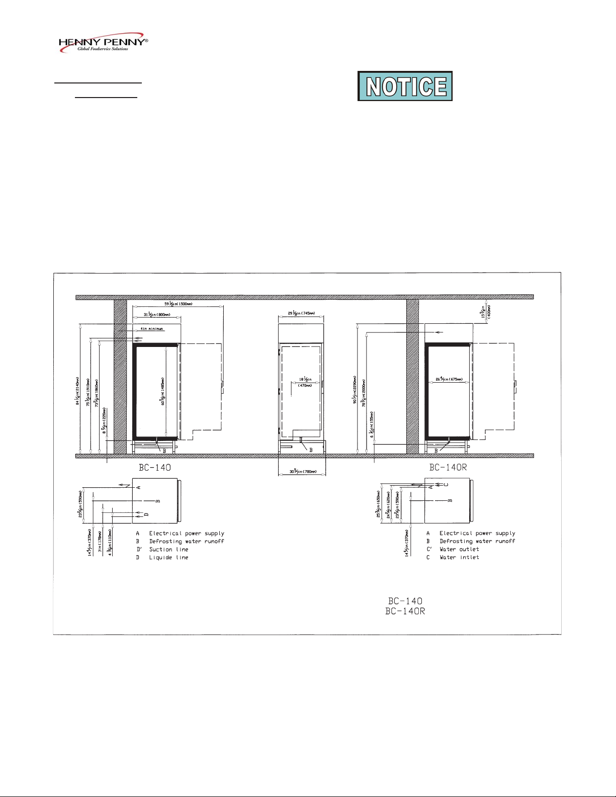
Clearances should be as follows:
BCC/BCR-140
T op 16 in. (400 mm) for air circulation
Left Side 4 in. (100 mm) for air circulation
Right Side 8 in. (200 mm) for air circulation
Back 4 in (100 mm) for air circulation
Front 26 3/8 in (668 mm) for door swing
2-4 505
Page 11
BCC/BCR-175
T op 16 in. (400 mm) for air circulation
Sides3 in. (76 mm) for air circulation
Front33 3/8 in. (847 mm) for door swing
Model BCC/BCR-140, BCC/BCR-175, BFR/BCR-350
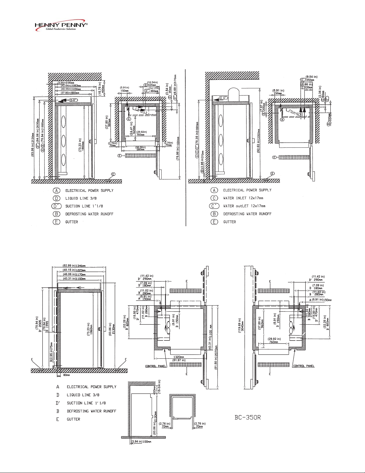
BFR & BCR-350
T op 16 in. (400 mm) for air circulation
Sides 3 in. (76 mm) for air circulation
Back 4 in. (100 mm) for air circulation
Pass Thru-Front and Back 38-1/8 in (970 mm) for
door swing
Solid Back-Front 38-1/8 in. (970 mm) for door
swing
505 2-5
Page 12

Model BCC/BCR-140, BCC/BCR-175, BFR/BCR-350
2-5. REFRIGERANT
INFORMATION Design Pressure
Refrigerant T ype Amount of Refrig. High Low
BCC-140 R404A 6 lbs. (2.7 kg) 406 psig 102psig
(28 bar) (7 bar)
BCC-175 R404A 5.5 lbs. (2.4 kg) 406 psig 102 psig
(28 bar) (7 bar)
2-6. REFRIGERA TION BCC/BCR-140
CAPACITIES -4o F (-20o C) at 6,800 BTU/hr (2.0 kw)
32o F (0o C) at 16,000 BTU/hr (4.7 kw)
BCC/BCR-175
-4o F (-20o C) at 11,300 BTU/hr (3.3 kw)
32o F (0o C) at 30,800 BTU/hr (9.0 kw)
2-7. BCC-175 WATER SUPPL Y
AND DRAIN
BCR-350
-4o F (-20o C) at 25,000 BTU/hr (7.3 kw)
32o F (0o C) at 58,000 BTU/hr (17.0 kw)
BFR-350
-4o F (-20o C) at 81,900 BTU/hr (24.0 kw)
-40o F (-40o C) at 35,500 BTU/hr (10.4 kw)
Water Supply
• W ater temperature should be at 50o F (10o C) + 5o )
• 1/2”-14 (15mm/21) diameter water supply
• 29 psi (2 bar) minimum pressure; 73 maxmum (5 bar)
• Supply inlet connector 3/8”-18 (12mm/17)
• 24.7 foot3/hour (0,7 m3/hour) minimum flow rate
Check the operation of the pressure valve. W ater should not flow
after the compressor stops. Adjust the valve where necessary ,
checking the condensation pressure.
Do not change any supply fittings or lines installed by the manufacture, or damage to the unit could result.
Do not use a flexible connection to make a drain trap, or water
overflowing the drain could result.
2-6 1105
Page 13

Model BCC/BCR-140, BCC/BCR-175, BFR/BCR-350
2-8. DE-ICING AND CLEANING
WATER DRAINAGE
2-9. REMOTE CONDENSING
UNITS INFORMATION
A floor trench, located in front of the door is recommended, with a
floor drain nearby , because of the quantity of water used in
cleaning.
For sanitary reasons, do not install a drain in the floor of the
blast chiller.
To ensure proper performance:
• When sizing a single condensing system for multiple blast chill-
ers, the total BTU’ s of all blast chillers should be considered
• An evaporator pressure regulator is required for combinations of
freezers and chillers on the same system
• Do not install a single condensing unit for more than 1 blast
freezer if they are to operate simultaneously; always install
separate condensing units for each blast freezer
• In addition to the compressor, condenser , and receiver, the unit
should be fitted with:
- low ambiant control
- high pressure, pressure controller
- automatic pump-down controller
- drier
- sight glass
- line
- insulation and refrigeration load
• Depending upon the ratings, the installation of a separate oil
separator, liquid valve, suction trap, etc, is also recommended
• Remote condensing unit compressors for blast chillers can be of
any type, but blast freezers, or blast chiller/freezers must use
semi-hermetic compressors, not hermetic
• Local area climate and codes help in detemining the size of the
condensing unit; use the maximum average temperature of the
summer, not the hottest temperature, or the unit will be over sized and over-priced for only a couple of weeks of hot
weather
• The condensing unit should have a separate electrical line
protected by a fuse or circuit breaker of the proper rating
505 2-7
Page 14

2-9. REMOTE CONDENSING
UNITS INFORMATION
(Continued)
Model BCC/BCR-140, BCC/BCR-175, BFR/BCR-350
T ake into account the pressure drops when determing the length
of the refrigeration line between the condensing unit and the blast
chiller/freezer . The refrigeration specifications given by the
manuafacturer for the blast chiller/freezers work properly with a
maximum length of 50 feet (15 m) and 13 feet (4 m) high
between the condensing unit and blast chiller/freezer . Beyond
this distance, a more powerful condensing unit will be needed.
To ensure proper operation, check for leaks on the
refrigeration system befor e leaving the installation.
Check the settings and correct operation of the saftey
devices on the condensing unit.
Installing Condensing Unit Outdoors
• Use a unit with bodywork designed for exterior installations, or
place the unit where it is protected from the elements (rain, sun,
etc.)
• Place the unit so the air flow is not against the prevailing winds
• Observe the minimum distances between the unit and nearby
walls, especially where the condenser is located and for
technical access
Installing Condensing Unit Indoors
• Preferably the remote condenser should be outdoors, or water-
cooled, connected to a chilling tower
• For air condensation units, make sure the ventilation can
dissipate the heat well enough to operate within the range of
temperatures given by the manufacture
• No electrical connection is required between the condensing unit
and the blast chiller/freezer; the unit should operate in “pumpdown” mode, being stopped and started by the low pressure,
pressure controller
• Install “traps” on the rising aspiration lines and provide slopes in
the line, so the oil returns to the compressor
2-8 505
Page 15

Model BCC/BCR-140, BCC/BCR-175, BFR/BCR-350
2-9. REMOTE CONDENSING
UNITS INFORMATION
(Continued)
Refrigeration Capacities
W e provide refrigeration capacity at two evaporation temperatures.
• Blast Chiller : 0°C (32°F) and –20°C (-4°F).
• Blast Freezer –20°C (-4°F) and –40°C (-40°F). Combined
units (Chiller/Freezer) are basically Blast Freezers.
The remote condensing units have to be selected in accordance with
these two data points. Refrigeration capacity of remote condensing
units have to be equal or higher than the requirement.
Example for a Blast Chiller:
Evaporation temperatures 0°C (32°F) -20°C (-4°F)
Refrigeration capacity needed 17000 W 7300 W
Remote condensing unit A 16900 W 7500 W
No Good
Remote condensing unit B 17100 W 7280 W
No Good
Remote condensing unit C 17010 W 7310 W
Both W ork
Blast Chiller/Freezers start-up at high internal air temperature,
because of the hot food. The condensing unit runs at a high evaporation temperature at beginning of the cycle and a low evaporation
temperature at the end of the cycle, when the food is cooled down.
Usually a single evaporation temperature is used when
specifying a condensing unit, because cold cabinets and
cold rooms run at a single temperature. But, blast chiller/
freezers require both datapoints, or the blast chiller/
freezer may not hold product at safe temperatures.
605 2-9
Page 16

Model BCC/BCR-140, BCC/BCR-175, BFR/BCR-350
2-9. REMOTE CONDENSING
UNITS INFORMATION
(Continued)
Running Range of Condensing Units
Evaporation temperatures, 32oF(0°C)/-4oF(-20°C)/-40°F(-40°C),
are used for refrigeration capacity selection. But evaporation
temperatures can be higher and lower than these values during the
cycle, depending on temperature, quantity , type and packing of the
food.
The remote condensing unit have to be able to run into the ranges
below .
• Blast Chillers : 45°F (7°C)/-22°F (-30°C)
• Blast Freezers and Combined : -4°F(-20°C)/-49°F (-45°C)
If remote condensing unit cannot run at the highest value of the
required running range, it is necessary to put a pressure regulating valve on the suction line of the compressor unit, in order to
keep the evaporation temperature of condensing unit into the
Blast Chiller/Freezer’s selection range.
2-10. OPERA TION CHECKLIST
Usually the range is on the data sheet of remote condensing units,
and refrigeration capacities are written for these temperatures.
Using a container 4 inches (100 mm) deep, filled with hot water, insert
the Frigiprobe into the water and start the unit in the chilling mode.
Refer to the graph at left.
• The water temperature is probably below 145oF (63oC), so phase
1 won’t be seen. The unit goes directly to phase 2.
• In phase 2, check that the compressor is regulating the air temperature limitation at around -4oF (-20oC). Use P02 information to
read the air temperature, page 3-10.
• In phase 3, check that the compressor is regulating the air temperature limitation at around 32oF (0oC). Use P02 information to
read the air temperature, page 3-10.
• In phase 4, check that the compressor is regulating the air temperature limitation at around 37oF (3oC). Read the air temperature
directly from the display .
2-10 605
Page 17

Model BCC/BCR-140, BCC/BCR-175, BFR/BCR-350
SECTION 3. OPERATION
3-1. INTRODUCTION This section provides operating procedures for the blast chiller.
Sections 1, 2, and 3 should be read, and all instructions should be
followed before operating the cabinet.
This section contains an explanation of all controls and components and information on operating procedures and daily
maintenance.
To avoid damage to the components,
do not lay a unit
on its side if it has a compressor. If the unit has been on
its side, the unit must be in an upright position for at least
an hour before power is applied to the unit.
Check all components for signs of being loose or damaged, and make sure the system has refrigerant.
3-2. OPERA TING CONTROLS Refer to Figure 3-1.
Fig. Item Description Function
No. No.
3-1 1 The On/Off button, when pressed, starts a Chilling Cycle;
it also must be pressed before any changes to the controls
can be made, and to start and stop the De-ice Cycle
3-1 2 Digital Display Shows the temperatures, the time (in a timer cycle), and
the information in the T echnical Mode
3-1 3 The Up and Down Arrows are used when changing times
or settings
3-1 4 The Alarm button is used to stop the optional alarm buzzer
and to enter the T echnical Mode
3-1 5 The TEMP button is used to select either the Chilling or
Freezing Mode
503 3-1
Page 18

Model BCC/BCR-140, BCC/BCR-175, BFR/BCR-350
3-2. OPERA TING CONTROLS
(Continued)
Fig. Item Description Function
No. No.
3-1 6 The De-Ice button is used to remove ice that may have
formed on the evaporator during a Chilling Cycle
3-1 7 The SELECT button is used to choose between a Timer
Cycle or a cycle using the Frigiprobe
3-1 8 The FAN LED is a green light which illuminates when
the fan is running
3-1 9 The Compressor LED is a green light which illuminates
when the compressor is running
3-1 10 The End-of-Cycle LED is a green light which illuminates
at the end of a Timer Cycle or Frigiprobe Cycle
3-1 11 The Alarm LED is a red light which illuminates when
the unit senses a fault in the system (ex: AL 1, AL 2, etc.)
3-1 12 The Chill LED is a green light which illuminates when
the Chilling Mode is selected
3-1 13 The Freeze LED is a green light which illuminates
when the Freezing Mode is selected
(only applicable
on BFR units)
3-1 14 The De-Ice LED is a green light which illuminates
when the De-Ice button is pressed
3-1 15 The Timer LED is a green light which illuminates when
the Timer Cycle is selected
3-1 16 The Frigiprobe LED is a green light which illuminates when
the Frigiprobe Mode is selected
3-2 503
Page 19

Model BCC/BCR-140, BCC/BCR-175, BFR/BCR-350
Figure 3-1. Operating Controls
503 3-3
Page 20

Model BCC/BCR-140, BCC/BCR-175, BFR/BCR-350
3-3. BASIC OPERA TION The Henny Penny blast chillers can chill food products with a
core temperature of 149ºF (65ºC), down to 40ºF (4ºC) within 4
hours (room ambient temperature may impact time it takes
to reach the desired temperature). But, for the above statements
to be accurate, the following conditions must be met:
a. The food product must not be thicker than 1-1/2 to 1-3/4
inches (40 to 45 mm).
b. Meats should be placed directly onto the racks, but products in
pans should be covered if possible. The steam from the product can form ice on the evaporator, which increases the chilling
or freezing time.
c. A minimum clearance of 1 inch (25 mm) between pans.
d. The best dishes or pans to use are stainless steel or aluminum.
Do not use polycarbonate (plastic) pans. The polycarbonate
acts as an insulator around the food product and makes it hard
to chill.
e. Do not exceed the product weight capacity specified by the
particular model of blast chiller. The BCC/BCR-140 has a 140
lb (65 kg) capacity , the BCC/BCR-175 has a 175 lb (80 kg)
capacity , and the BCR-350 has a 350 lb (160 kg) capacity .
Start-up
1. For the same batch of product (same type of product), load all
the product at one time, so the door does not need to be
opened while in operation.
For a mixed batch (different types of product), load each type
as ready , and place the Frigiprobe (located on the left side,
middle of the unit) into the product which will chill the quickest.
2. If using the Frigiprobe for same batch of product, place probe
into product at this time.
3. Press to turn unit on. and should come on
after 25 seconds.
3-4 605
Page 21

Model BCC/BCR-140, BCC/BCR-175, BFR/BCR-350
3-3. BASIC OPERA TION 4. Press to select the Chilling Mode. (Chilling Mode
(Continued) or Freezing Mode can be selected on BFR units.)
or and or , stay on with turned
to the OFF position.
5. Press to choose the Frigiprobe Mode or the Timer
Mode. W ith the Probe Mode selected, the digital display
alternately shows the core temperature of the product, and the
elapsed time of the cycle. If the Timer Mode is selected, the
digital display alternately shows the air temperature and the time
(hours and minutes) remaining in the cycle.
The buzzer sounds 1 minute after the Probe Mode is selected,
unless the temperature is above 140ºF (60ºC). Then the
buzzer sounds when 140ºF (60ºC) is reached.
6. Set the time in the Timer Cycle, if necessary , using . The
time is affected by the thickness of the food product, weight,
food loading temperature, and food’ s packaging. The buzzer
sounds 1 minute into the Timer Cycle.
A void opening the door once the cycle has started. This
lengthens the time it takes to reach the desired temperature.
7. At the end of the cycle (40ºF (4ºC) in the Probe Mode)
the buzzer sounds and the unit automatically starts the Hold
Cycle. The buzzer sounds for 30 seconds, or press to
stop it. In the Hold Cycle, the product will be held at 37ºF
(3ºC) in the Chilling Mode, or at -0.4ºF (-18ºC) in the Freezing
Mode.
8. The product can remain in the unit for up to 12 hours, or
can be removed from the unit and placed in a cold storage
case.
605 3-5
Page 22

Model BCC/BCR-140, BCC/BCR-175, BFR/BCR-350
3-3. BASIC OPERA TION A temperature conversion chart is provided for your
(Continued) convenience:
Temperature Conversion Chart
88ºC 190ºF
80ºC 176ºF
70ºC 158ºF
65ºC 149ºF
60ºC 140ºF
50ºC 122ºF
40ºC 104ºF
30ºC 86ºF
10ºC 50ºF
4ºC 40ºF
0ºC 32ºF
-10ºC 14ºF
-20ºC -4ºF
-30ºC -22ºF
-40ºC -40ºF
3-6 503
Page 23

Model BCC/BCR-140, BCC/BCR-175, BFR/BCR-350
3-4. DE-ICING Henny Penny recommends performing the de-icing process after
every 3 cycles and at the end of each day . This eliminates any
ice that may have formed around the evaporator during the Chilling
or Freezing Cycles. Failure to follow this procedure increases the
time it takes to cool the product and may lead to unsafe product.
1. Remove all product from the unit.
2. Close the door.
3. Press to turn the unit on.
4. Press . The digital display now shows d. 01 . The
compressor will not come on, but the evaporator fan comes on
and pulls warm air created by the de-icing elements, across
the evaporator .
5. Allow the De-ice Cycle to run for a minimum of 10 minutes
and a maximum of 25 minutes. The unit automatically turns off
when the evaporator has been de-iced, and reaches a temperature of 77ºF (25ºC).
If the above procedures does not remove all the ice from
the evaporator, the length of time, and the temperature at
which the De-ice Cycle turns the unit off can be adjusted.
See the Programming Section.
503 3-7
Page 24

3-5. CLEANING Daily:
1. Make sure the power switch is in the off position.
2. Remove all product from the unit.
3. Remove the racks and pans from the unit and clean with
soap and water at a sink.
4. Clean all surfaces, including the Frigiprobe, with a soft cloth,
soap and water.
Do not use steel wool, other abrasive cleaners or
cleaners/sanitizers containing chlorine, bromine, iodine
or ammonia chemicals, as these will deteriorate the
stainless steel, and glass material, and shorten the life of
the unit.
Do not use a water jet (pressure sprayer) to clean the
unit, or component failure could result.
Model BCC/BCR-140, BCC/BCR-175, BFR/BCR-350
Do not use abrasive cleaners!
5. Clean around the electronic controls and the door seal with
a soft, damp cloth.
6. The unit is now ready for operation.
Henny Penny has the following cleaners available:
Foaming Degreaser - Part no. 12226
Food Service Sanitizer - Part no. 12059
Stainless Steel Cleaner/Polish - Part no. 12060
See your local distributor for details.
Weekly:
Once a week, the evaporator coils need cleaning to ensure the unit
runs efficiently and to remove corrosive build-up on the coils.
To avoid personal injury, move the power switch to OFF
and disconnect main circuit breaker.
Wear protective gloves to reduce the risk of cuts from
the coil.
1. Remove the racks and pans from the unit
2. Using a flat-head screwdriver, remove the screws securing the
evaporator cover and swing the cover out to access the coils.
3-8 605
Page 25

Model BCC/BCR-140, BCC/BCR-175, BFR/BCR-350
3-5. CLEANING (Continued) 3. Mix a bicarbonate of soda solution (baking soda) of one
teaspoon per litre of water in a spray bottle. Spray the coils
completely , concentrating on the top and bottom areas as
shown in photo at left. Allow to soak for about 5 minutes.
Do not use a water jet (pressure sprayer) to clean
the unit, or component failure could result.
Do not use pointed or shart objects to cleaning coils
or damage to the coil could result.
4. Using a soft cloth or sponge and fresh water, rinse and
clean the coils completely.
5. Replace screws in cover and unit is now ready for use.
Monthly: BCC-140 Only
At least once a month the air condenser needs to be cleaned of
dust or obstructions for the unit to run efficiently and to reduce
energy use of the unit.
1. Remove all electrical power supplied to the unit by turning off
the wall circuit breaker.
2. Using a flathead screwdriver, remove the screws from the
front panel of the unit. Pull panel down and press in on the
side of the panel to release the tabs, and remove the panel
from the unit.
3. Use a vacuum cleaner, or soft brush to remove the dust, or
other obstructions from the condenser.
4. Finish cleaning with compressed air if possible, blowing the air
from the rear of the condenser.
Do not use a wire brush to clean the condenser, or damage
to the condenser could result.
5. Replace the front panel, and reconnect the electrical supply,
and unit is now ready for use.
3-6. SEASONAL OR 1. Remove all electrical power supplied to the unit by turning off
PROLONGED SHUTDOWN the wall circuit breaker.
2. Make sure the inside of the unit is clean and completely dry.
3. Leave the door slightly ajar to prevent smells from developing
inside the unit.
205 3-9
Page 26

Model BCC/BCR-140, BCC/BCR-175, BFR/BCR-350
3-7. PROGRAMMING Information about the operation settings can be accessed by
pressing . These settings can also be changed while in the
different steps. The following information can be accessed:
After pressing , a delay occurs before the desired
number appears in the display , and the number in the left
Displayed Step
column shows for 2 seconds. You then only have 12 seconds
to change the setting.
00
01
02
03
04
Not Available at this time.
Not Available at this time.
Internal air temperature. Press three times and the
digital display shows the air temperature during a Probe Cycle.
Evaporator temperature. Press 4 times and the digital
display shows the evaporator temperature during the De-icing
Cycle.
T ype of program setting indicated by the jumper
link located on the control board. Press 5 times and
the digital display shows a number between 5 and 9, which
indicates the position of the jumper on the control board. The
control panel area does not have to be accessed to obtain the
information. (See chart at left.) Henny Penny controls should
show the number 6 in the display .
05
3-10 605
T emperature of the Holding Cycle, after the Chilling or
Freezing Cycle. Press 6 times and the digital display
shows the air temperature. This is the temperature at which the
unit stays during the Hold Cycle.
Page 27

Model BCC/BCR-140, BCC/BCR-175, BFR/BCR-350
3-7. PROGRAMMING The holding temperature can be changed at this time by
(Continued) using . Factory setting for air temperature is 37ºF (3ºC)
Displayed Step
06
07
08
in the Chilling Mode and 0ºF (-18ºC) in the Freezing Mode.
The minimum temperature setting is 32ºF (0ºC) in the Chilling
Mode and -31ºF (-35ºC) in the Freezing Mode. The maximum
is 50ºF (10ºC) in the Chilling Mode and 32ºF (0ºC) in the
Freezing Mode.
Maximum duration of De-icing Cycle (minutes). Press
7 times and the digital display shows the time duration of
the De-icing Cycle. The factory setting is 25 minutes, but this
can be changed to a maximum setting of 60 or a minimum of
25 by using .
Evaporator temperature for the end of De-Icing Cycle.
Press 8 times and the digital display shows the evaporator temperature at which the controls automatically turn off
the De-icing Cycle. The factory setting is 77ºF (25ºC), but this
can be changed to a maximum setting of 104ºF (40ºC) or the
minimum of 50ºF (10ºC) by using .
T emperature differential befor e high air temperature
alarm. Press 9 times and the digital display shows the
number of degrees, above the holding temperature, at which an
alarm sounds, indicating the hold temperature is too high.
The factory air temperature setting is 27ºF (-3ºC), but can
be changed to a maximum setting of 54ºF (12ºC) or a
minimum temperature of 7ºF (14ºC) by pressing .
09
605 3-11
T emperature differ ential before low air temperature
alarm. Press 10 times and the digital display shows
the number of degrees below the holding temperature, at which
an alarm sounds, indicating the hold temperature is too low .
The factory air temperature setting is 27ºF (-3°C), but can
be changed to a maximum setting of 54ºF (12°C) or a minimum of 18ºF (-8°C) by pressing .
Page 28

Model BCC/BCR-140, BCC/BCR-175, BFR/BCR-350
3-7. PROGRAMMING The duration of time the temperatures (in 9 and 10
(Continued) above) must remain at before the alarms will sound.
Displayed Step
Press 11 times and the digital display shows the time at
which the high and low temperatures (no. 9 and 10 above) must
remain before the alarm sounds.
10
The factory setting is 20 minutes, but can be changed to a
maximum setting of 60 minutes or a minimum of 10 minutes
by pressing .
This means that the temperature must remain at a too high
or too low temperature for 20 minutes before an alarm sounds.
11
International Only. A Frigiprobe temperature at which
the compressor turns off in a Chilling Cycle, to prevent
freezing of the product. Press 12 times and the digital
display shows the temperature at which a sensor in the
Frigiprobe turns off the compressor during a Probe Mode.
This prevents the outer surfaces of the product from freezing,
however the cooling time will be greatly increased.
The factory setting is 39ºF (4ºC), but can be changed to a
maximum setting of 122ºF (50ºC) or a minimum of 32ºF
(0ºC) by pressing .
Do not change this setting lower than the setting used in parameter 22, (next page).
This function will only activate when the factory setting is
changed to above 40ºF (4ºC). England must have a setting
of 3ºC (37ºF).
12
3-12 605
Re-initialize the controls to factory settings. Press the
13 times and the digital display shows “DEF”, at which
time is pressed and the unit shuts down. Re-initialization
is now complete.
After re-initialization, the controls default back to factory
settings. The temperature will be in Celsius and the values in
steps 12, 16, and 18 of this section need to checked to be
accurate for the country in which the unit is installed.
Page 29

Model BCC/BCR-140, BCC/BCR-175, BFR/BCR-350
3-7. PROGRAMMING Blast chilling, low side air temperature limit, when using
(Continued) the Frigiprobe, in step 12 of this section. Press
14 times and the low side air temperature, at which the com-
Displayed Step
20
pressor cycles on and off, shows in the display . This temperature is used in preventing the product from freezing, while in
the Chilling Mode, which is described in step 12.
The factory setting is -4ºF (-20ºC), but can be changed to a
maximum setting of 32ºF (0ºC) and a minimum setting of
-31ºF (-35ºC), by using .
21
22
Blast chilling, high side air temperature limit, when using
the Frigiprobe, in step 12 of this section. Press
15 times and the high side air temperature, at which the compressor cycles on and off, show in the display . This temperature is used in preventing the product from freezing, while in the
Chilling Mode, which is described in step 12.
The factory setting is 32ºF (0ºC), but can be changed to a
maximum setting of 50ºF (10ºC), and a minimum setting of
23ºF (-5ºC), by using .
Frigiprobe, end of cycle temperature setting. Press
16 times, and the temperature at which the Probe Cycle ends
and the Hold Cycle starts, shows in the display .
The factory setting is 39ºF (4ºC) for blast chilling and
0ºF (-18ºC) for blast freezing. The blast chilling is factory set at
the maximum setting, but can be changed to a minimum setting
of 32ºF (0ºC), by using .
The blast freezing temperature can be changed to a maximum
temperature of 32ºF (0ºC), and a minimum temperature
of -31ºF (-35ºC), by using .
The maximum settings for U.S.A. is 39ºF (4ºC), and for
England is 37ºF (3ºC).
605 3-13
Page 30

Model BCC/BCR-140, BCC/BCR-175, BFR/BCR-350
3-7. PROGRAMMING Frigiprobe temperature for when the buzzer sounds at
(Continued) the start of a cycle. Press 17 times, and the tempera-
Displayed Step
23
ture that the buzzer sounds when the product
“danger zone” temperature, and must be cooled to a “safe”
temperature within the recommended time, is shown in the
display .
The factory setting is 140ºF (60ºC), but can be changed to a
maximum setting of 176ºF (80ºC) and a minimum setting of
122ºF (50ºC) by using .
The settings for the U.S.A. must be 140ºF (60ºC) and for
England, 158ºF (70ºC).
has reached the
24
30
Intermediate Printer Setting. Press 18 times and a
printing temperature, between the starting temperature and the
ending temperature, can be set. Along with printing the temperature information at the end of a cycle, the printer can be set
to capture temperature information in the middle of the cycle.
The factory setting is -40ºF (-40ºC), but can be changed to a
maximum setting of 176ºF (80ºC) and a minimum setting of
40ºF (-40ºC) by using .
A setting lower than parameter deactivates this function.
Selecting Fahrenheit or Celsius. Press
19 times and ºF or ºC shows in the display . Press
to change from ºF to ºC, or vice versa.
(Once is pressed, the display goes blank.)
22
3-14 1105
Page 31

Model BCC/BCR-140, BCC/BCR-175, BFR/BCR-350
SECTION 4. TROUBLESHOOTING
4-1. TROUBLESHOOTING GUIDE
PROBLEM CAUSE CORRECTION
The evaporator is iced-up • The door was closed • Open the door when following
after a De-icing Cycle the de-icing procedure
• Evaporator temperature at end • Increase the setting of Step 8 in
of De-icing Cycle too low Programming Section
• Maximum time of De-icing Cycle • Increase the setting of Step 7 in
too short Programming Section
T oo much water on • The unit has been shut down • Start a De-icing Cycle
evaporator fins without a De-icing Cycle
Slow to decrease • T emperature of room too high • V entilate the room
in temperature (decline in
performance) • Back of unit too close to • Change the location of the
the wall unit
Slow to decrease • Condenser obstructed by dirt • Clean the condenser
in temperature (decline in
performance) • Evaporator iced up • Perform a De-icing Cycle
Display temperature does • In Probe Mode, the display • Normal
not match the actual inlet air shows the product temperature
temperature (No alarm)
All indicator lights off and • Check electrical supply • Plug unit into receptacle, or
ON/OFF switch will not reset wall circuit breaker
operate
• Fuse of control board blown • Change the fuse
603 4-1
Page 32

Model BCC/BCR-140, BCC/BCR-175, BFR/BCR-350
4-2. ALARM MESSAGES In the event of a system failure, the digital display will show an
alarm message. These messages are coded; “AL-1”, “AL-2”,
“AL-3”, “AL-5”, and “AL-6.” When an alarm occurs, the red
alarm LED will illuminate and a buzzer (optional) will sound. Press
the Alarm button to stop the buzzer .
The unit can operate on auto backup if an alarm sounds for a
faulty probe. Must select the Timer Mode, and enter a time.
Display Cause Correction
“AL-1” Faulty air temperature Replace the probe; unit can operate on auto
probe backup until a new probe is installed
“AL-2” Faulty evaporator probe Replace the probe; the De-icing Cycle can operate at
50% of the setting in step 7 of the Programming Section
“AL-3” Faulty Frigiprobe Replace the probe; the Frigiprobe Mode will not
operate, but the unit will operate in the Timer Mode
“AL-5” Temperature too low Faulty control board - replace control board;
in the hold mode faulty contactor - replace contactor
“AL-6” Temperature too high in Faulty control board - replace control board;
the hold mode door opened too much - make sure door stays
closed as much as possible
4-2 603
Page 33

Model BCC/BCR-140, BCC/BCR-175, BFR/BCR-350
G L O S S A R Y
Refrigerated Equipment
air temperature probe a temperature sensing device that controls the temperature after the Chilling
Cycle has been completed
ballast a device located on a fluorescent lamp fixture that helps the lamp power up
quickly
chilling the feature that cools products to a safe temperature
compressor the unit that pumps the refrigerant through the system
condenser a part of the system that changes the refrigerant to a liquid
cycle an operational process such as chilling, freezing, hold, timer
defrosting / de-icing the feature that prevents ice build up inside the unit
evaporator a part of the system that changes the refrigerant to a gas
evaporator probe a temperature sensing device that stops the de-icing cycle when completed
freezing the feature that quickly freezes product
Frigiprobe a temperature sensing device that is inserted into the product
hold the feature that maintains the product at a safe temperature
LED a light which illuminates to indicate the cycle or mode is in use
mode a programming segment used to set up the various cycles, such as chilling,
freezing, hold, timer, Frigiprobe
product a food item chilled or frozen in the unit
refrigerant a chemical coolant used by the refrigeration system
setpoint a preset chilling or freezing temperature; the setpoint is a programmable feature
technical mode used to program the unit’s feature
timer the feature that chills and freezes on a timed basis rather than using the
Frigiprobe
603 G-1
Page 34

*FM05
-
027
-F*
Henny Penny Corp., Eaton, Ohio 45320, Revised 09-27-07
Henny Penny Corporation
P.O.Box 60
Eaton,OH 45320
1-937-456-8400
1-937-456-8402 Fax
Toll free in USA
1-800-417-8417
1-800-417-8434 Fax
www.hennypenny.com
 Loading...