

559-734-7451 800-367-5480 FAX 559-734-7460
INSTALLA TION INSTRUCTIONS
Thank you for purchasing a quality Hellwig Product.
PLEASE READ THIS INSTRUCTION SHEET COMPLETELY BEFORE STARTING YOUR INSTALLATIONPROCEDURES.
4th Leaf - LP35
TORQUE TABLE
BOLT SIZE: 3/8” = 20-30 ft. lbs. – 7/16” = 35-45 ft. lbs. – ½” = 50-70 ft. lbs. – 9/16” = 70-90 ft. lbs
SAFETY: PARK YOUR VEHICLE ON A FLAT LEVEL SURFACE, SET THE PARKING AND CHOCK THE FRONT TIRES.
NOTE: THIS KIT INCLUDES LOCKNUTS WHICH REQUIRE TIGHTENING WITH A WRENCH AFETR BEING STARTED BY
HAND.
NOTE: IF YOUR VEHICLE IS EQUIPPED WITH A BRAKE FLUID PROPORTIONING VALVE ON THE REAR AXLE READ
INSERT (R-362)
IMPORTANT NOTE: IF YOUR VEHICLE IS EQUIPED WITH A FACTORY CONTACT OVER LOAD IT MUST BE REMOVED
BEFORE INSTALLING THE NEW HELPER SPRINGS.
1. Raise the rear of the vehicle by the frame so that the rear tires are just slightly contacting the floor. Be sure to
Block the front tires and use Jack Stands to support the vehicle by the frame. This will increase the vehicle’s
spring arch to ease installation.
2. Lay out the spring leaves into two (2) sets. Each will consist of a long, medium and a short leaf. The hole in
the middle of the leaves is punched (1”) off center. Lay the leaves so that t he long ands are all in the same
direction.
3. Stack the leaves so that the short leaf is on the bottom and the long leaf is on the top. Use the (3/8”) bolt, nut
and lock washer that are provided to tighten the spring stack tightly. Tighten this center bolt completely.
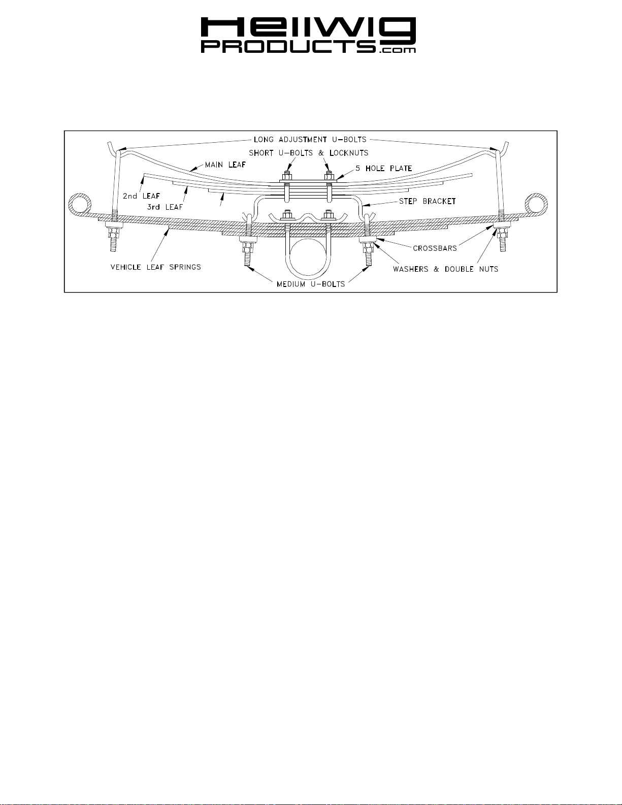
4. Place the spring stack on top of the Step Brackets and install the (5) hole plate on top of the spring stack.
Using the small U-bolts and the (7/16”) lock nuts that are provided mount the spring stacks to the Step
Brackets with the (5) hole plate. Tighten completely. Be sure that the springs are straight in line with the Step
Bracket. SEE DIAGRAM.
5. Place the assembled spring on top of the truck springs. In most cases the long ends of the springs go towards
the rear. Align the springs to be centered over, and in line with the truck springs from front to rear. Front to
rear adjustment may be needed to position the Helper Springs and clear any vehicle components or spring
alignment clamps.
6. Install the medium U-bolts over the ends of the Step Brackets and install the crossbar with the washers and
double nuts to connect the Step Brackets to the truck springs. Leave loose at this time.
7. Place the long U-bolts on the ends of the Helper Springs and install the crossbars with the washers and double
nuts. Leave loose at this time. A C-clamp may be needed to compress the helper spring ends to attach the
crossbars and start the threads of the nuts.
READ OPPOSITE SIDE COMPLETELY
208 ( R-208 ) 02/27/04

559-734-7451 800-367-5480 FAX 559-734-7460
8. Align the U-bolts and the Helper Springs to be centered and in line with the truck springs. Tighten the medium
length U-bolts on the Step Bracket completely and double nut.
9. Lower the vehicle to the ground and tighten the end U-bolts to attain the desired height and tension. Double nut
the U-bolt or loosening will result. Tightening the end U-bolts will increase and loosening will relieve tension.
Be sure to double nut after each adjustment. Be sure to check for clearance above the Helper Spring to the
body, fuel filler hose etc..
10. The minimum tension adjustment is having enough tension on the end U-bolts so that they do not loosen or
rattle and move when the vehicle is driven over rough or bumpy surfaces. The maximum is having the end U bolts tightened so that the ends of the Helper Springs are no closer than (1/4”) above the vehicle springs.
11. Check your installation for clearance on all undercarriage components; wires, fuel and brake lines. Test drive the
vehicle and recheck your installation, adjust as needed. Recheck on a monthly regular basis thereafter.
IMPORTANT NOTES, WARNINGS AND TIPS
READ THIS INSTRUCTION SHEET COMPLETELY BEFORE STARTING YOUR INSTALLTION
IMPORTANT NOTE: CHECK YOUR INSTALLATION. ARE ALL NUTS AND BOLTS SECURELY
TIGHTENED AND DOUBLE NUTTED WHERE PROVIDED? BOUNCE THE VEHICLE CHECKING
FOR CLEARANCE ON ALL UNDERCARRAIGE COMPONENTS, MUFFLERS, GAS FILLER PIPES,
BRAKE LINES, EMERGENCY BRAKE CABLE, AIR CONDITIONING LINES, RUBBER BOTTOMING
PADS, ETC.
If this unit is to be installed on any DODGE VAN OR MOTORHOME CHASISI model numbers, B300, B400,
MB300 OR MB400 and F30, F40, F44 with plastic molded gas tank a special clearance bracket is required and is
available through your local dealer or from Hellwig Products Company (SB621).
For installation on: Wagoneer, Cherokee and J-Series Pick-ups (25350). Locate the double studded plate assembly
provided in this kit. This bracket mounts on the front half of the rear spring. Install this bracket with the legs pointing
outward to the body of the vehicle. The flat plates will be parallel to the frame and the legs or studs parallel to the
ground. One leg will nest in the grove on the accessory s pring. The other leg under the vehicle’s original spring.
Place the final plate on the legs of the bracket and apply washers and double nut.
Before attempting the installation of any Hellwig Accessory Spring , be sure and identify the vehicle to which the
accessory spring will be installed as either being or not being equipped with height sensing brake fluid proportioning
valve. If a vehicle is equipped with the brake fluid proportioning valve on the rear axle, it is recommended that any
Hellwig Full Time Accessory Spring NOT be installed. Only the Progressive Rate Accessor y Springs are to be installed on these vehicles. Some of the vehicles manufacturers (FORD, GM, DODGE) have recommended an adjustment or modification of the brake system. If the vehicles height or weight requirements have been changed due to the
suspension modifications or unusual load situations, contact your local dealer for correct adjustment after installation.
If you have any questions about the application, please contact Hellwig Products Company inc.
IMPORTANT NOTE: Hellwig helper springs are designed to increase the “ Level Load” carrying capacity of your
vehicle. Never load the vehicle that this unit is installed on beyond the manufacturer’s maximum gross vehicle
weight rating.
ATTENTION INSTALLER: BE SURE THAT THE CUSTOMER RECEIVES THIS INSTRUCTION SHEET,
ALL IMORTANT NOTE CARDS AND THE WARRANTY FORM
208 ( R-208 ) 02/27/04
 Loading...