

559-734-7451 800-367-5480 FAX 559-734-7460
INSTALLA TION INSTRUCTIONS
Thank you for purchasing a quality Hellwig Product.
PLEASE READ THIS INSTRUCTION SHEET COMPLETELY BEFORE STARTING YOUR INSTALLATION
TORQUE TABLE
BOLT SIZE: 3/8” = 20-30 ft. lbs. – 7/16” = 35-45 ft. lbs. – ½” = 50-70 ft. lbs. – 9/16” = 70-90 ft. lbs.
SAFETY: BEFORE STARTING YOUR INSTALLATION, BE SURE TO SET PARKING BRAKE AND CHOCK TIRES.
IMPORTANT NOTE: HELLWIG HELPER SPRINGS ARE DESIGNED TO INCREASE THE “LEVEL LOAD” CARRYING CAPACITY
OF YOUR VEHICLE. NEVER LOAD THE VEHICLE THAT THIS UNIT IS BEING INSTALLED ON BEYOND
THE MANUFACTURER’S MAXIMUM GROSS VEHICLE WEIGHT RATING.
NOTICE: DO NOT, ATTEMPT TO INSTALL THIS UNIT ON CHEVY/GMC ASTRO VANS OR ANY OTHER VEHICLE WITH PLAS-
TIC COMPOSITE SPRINGS.
DO NOT, ATTEMPT TO INSTALL THIS UNIT ON JEEP CHEROKEE MINI WAGON, DUE TO CLEARANCE AND SPRING
HEIGHT. THIS UNIT MAY COME INTO CONTACT WITH THE UNDERCARRAIGE PANELS AND CAUSE DAM
AGE WHILE THE VEHICLE IS IN MOTION. RECOMMENDED UNIT FOR THIS VEHICLE IS PART NUMBER :
EZ -550
FOR ADDITIONAL INFORMATION CALL 1-800-367-5682 OR (1-800-367-5480 OUTSIDE OF CA.)
NOTE: IF YOUR VEHICLE IS EQUIPPED WITH A BRAKE FLUID PROPORTIONING VALVE ON THE REAR AXLE READ INSERT
(R-362)
1. Be sure the vehicle is on flat hard surface, use tire blocks and safety stands. Raise up the vehicle by the frame so that the tires are
just contacting the floor.
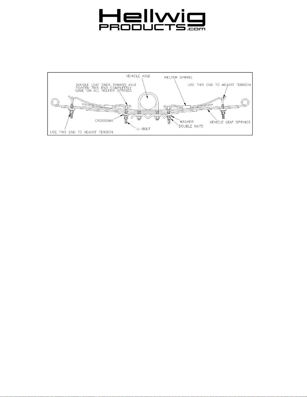
2. Place the accessory spring on top of the springs as per drawing.
NOTE: The short assembly will mount in front and the long assembly will mount on the rear of vehicle’s springs.
Place the leaves as close as possible to the axle without making contact.
3. Install the U-bolts on the accessory springs using the crossbars, washers and nuts which are provided. Tighten the U-bolts closest
to the axle completely. Double nut this U-bolt.
4. Install the crossbar, washer and nuts on the end U-bolt. Tighten until enough threads show through to install the locknut.
5. To adjust the spring for more load capacity remove the lock nut from the end U-bolt and draw the U-bolt tighter. Be sure to
double nut after each adjustment that is made.
6. Bounce the vehicle and check for clearance on all undercarriage components. Check to see that all wiring, brake and fuel lines
are free and clear of your installation.
7. Recheck your installation. Are all lock nuts installed? Are the U-bolts closest to the axle drawn down completely tight. After one
week of driving check your installation to see that it is properly tight and has not shifted. Recheck on a monthly regular basis
thereafter.
WHEN INSTALLING THIS UNIT ON COURIER OR MAZDA PICKUPS 1982 OR LATER. IT WILL BE NECESSARY TO REPLACE THE EMERGENCY BRAKE CABLE RETAINER BOLT ON THE MIDDLE SPRING CLIP. YOUR INSTALLATION
KIT HAS A NEW BOLT FOR THE CHANGE. WHEN THE NEW BOLT HAS BEEN INSTALLED THE SPRING CLIP EARS
MUST BE BENT DOWN FLAT AGAINST THE SPRING. COMPLETE THE INSTALLATION AS ABOVE.
ATTENTION INSTALLER: BE SURE THAT THE CUSTOMER RECEIVES THIS INSTRUCTION SHEET, ALL IMORTANT
NOTE CARDS AND THE WARRANTY FORM
( R-223) 05/10/04
 Loading...