

Heatmiser UH8 Installation Manual
Model: UH8
Wiring Centre2 3Model: UH8
UH8 – Installation Manual
Description
The UH8 is an 8 Zone wiring centre for use with Heatmiser
230v thermostats.
The UH8 can be used to control any actuator or valve which requires a
230v AC signal. At the same time the UH8 oers the ability to operate a
boiler or other heat source through a volt free output.
Additional outputs designed for use with underoor heating systems
are also included as standard. These are the pump and valve outputs
which would normally operate a manifold pump or a manifold valve.
Zone 8 can be used as an isolated radiator zone by using the
UFH/RAD switch.
If the switch is set to RAD;
When zone 8 calls for heat this will provide an output to a radiator
zone valve and the boiler, but WILL NOT enable the underoor
heating pump/valve output.
If the switch is set to UFH;
When Zone 8 calls for heat, this will act as an underoor heating zone,
by enabling the actuator, boiler and pump/valve outputs.
Any output which is not needed can be ignored.
Installation
The UH8 can be mounted directly to a wall using four screws or
alternatively, the unit can be DIN rail mounted.
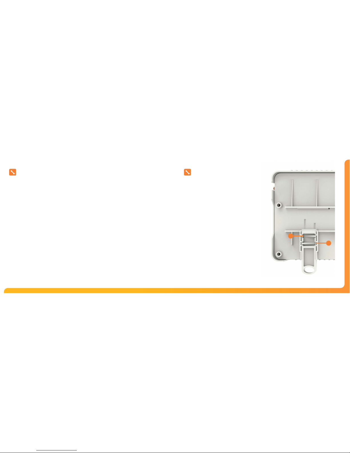
When DIN Rail mounting, you first need to insert the two clips
provided on the back of the UH8, as shown in the image;
• On the back of the UH8, position the clip in the middle
and slide down.
• Points A and B locate in the corresponding holes and
lock into place.
• Locate the UH8 onto the DIN rail from the top.
• Pull the clip down and push the bottom of the UH8 onto
the DIN rail.
• Releasing the clip will lock the UH8 in place on the DIN rail.
To remove the UH8, pull both clips down and remove from the DIN rail.
B
A
Insert clip here.
Then Slide down to lock in place.
Wiring Centre4 5Model: UH8
Zones 1…8
Zones outputs are clearly marked
L = live out to actuator or valve
N = neutral to actuator or valve
There are two connections live (L) and neutral (N), both terminals
marked L are the same and both terminals marked N are the same.
Each zone output corresponds to the thermostat wired in at the
top of the pcb.
UFH Pump
Used for an underoor heating manifold pump.
Connections are clearly marked
L = Live
E = Earth
N = Neutral
When an under-oor heating zone sends a call for heat to the UH8, the
live & neutral output will supply 230v to the manifold pump.
It is recommended that this is fed through a high limit switch placed
on the heating manifold, to protect against mechanical failure of the
manifolds temperature control.
UFH Valve
Used for an underoor heating manifold valve.
Connections are clearly marked;
Gr = Grey
Or = Orange
L = Live
E = Earth
N = Neutral
When an under-oor heating zone sends a call for heat to the UH8,
the live & neutral output will supply 230v to the manifold valve.
The auxiliary wires of the valve, usually grey & orange, are wired to the
Gr & Or terminals.
Fuses
Fuse 1. 5amp, 20mm anti-surge fuse, this fuse supplies
power to all 230v outputs from the board it protects the zone,
pump/valve outputs.
Connections
Mains Supply
Power supply into the UH4 which should be fused at 5 amps these
connections are marked
L = live or phase 230v AC 50/60Hz
N = Neutral
E = Earth
Heat Enable
This is the main call for heat for the system, there are 3 connections;
LS = Live Supply
E = Earth
LR = Live Return
Electrically this is a volt free switch, whatever supply is placed on the
LS connection, is fed to the LR connection when there is a call for heat.
UH8 Wiring
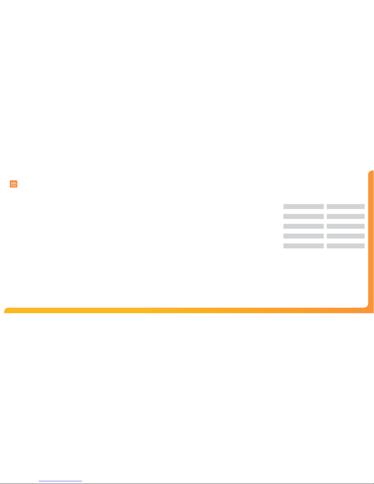
Ratings
Number of Heating Zones 8
Neon Indication Y
DIN Rail Mounting Y
Supply 230v AC 50Hz 1 Phase
Relay Load Max 3 Amp Resistive
Total Load Max 5 Amp Resistive
IP Protection IP20
Installed Dimensions (L,H,D) 384 x 148 x 60mm
Weight 800g
 Loading...