

Page 1

HEATMISER PLUS
INSTRUCTION & SETUP MANAUL
Features in this manual are only available on the Heatmiser Plus with the software version 5.4
Revision 2
18/08/2002
Revision 2 18th August 2002 Page 1
Page 2

Heatmiser Plus User Manual
SUBJECT PAGE NUMBER
Contents Page 2 & 3
KeyPad Layout 4
Standard Terms 5
Specification
Installation Notes
Control Specification
6
6
Normal RUN Mode
Scroll Screens 7
Increase/Decrease
7
temperature temporarily
View Technical Screen (Log) 7
Service Mode 8
Override Function 8
Holiday Function 8
Program Mode
DATA- Program switching times and temperatures 9
TIME- Setting the current time and date 10
CODE- How to change the User Code 11
HOLIDAYS- How to program the holiday periods 11
Revision 2 18th August 2002 Page 2 of 38
Page 3

Heatmiser Plus User Manual
SUBJECT PAGE NUMBER
Configuring the Heatmiser Plus
Configuring the system 12
Resetting the System back to the factory defaults 14
Engineers setup- Setting up the individual
zones
1.Calibrating the sensors
2.Setting the maximum override time
3.UP Arrow key “Offset Limit”
4.DOWN Arrow key “Offset Limit”
5.Setting Up Boiler Sequencer (Fixed Flow)
6.Setting Up Boiler Sequencer (Variable Flow)
7.Setting Up Compensated zones
8.Setting Up Optimised Zones
9.Setting Up HiLo Zones
16
16
16
17
18
19
22
25
26
2. Programming the zone & relay titles 27
3. Changing the code 28
4. Monitor - View temperature log 28
5. Hours Run 28
6. Clear Monitor 28
7. Override / Alarm inputs 29
8. Wiring instructions 30
Wiring Diagrams 31-37
Heatmiser Sensor Information 38
Revision 2 18th August 2002 Page 3 of 38
Page 4
Heatmiser Plus User Manual
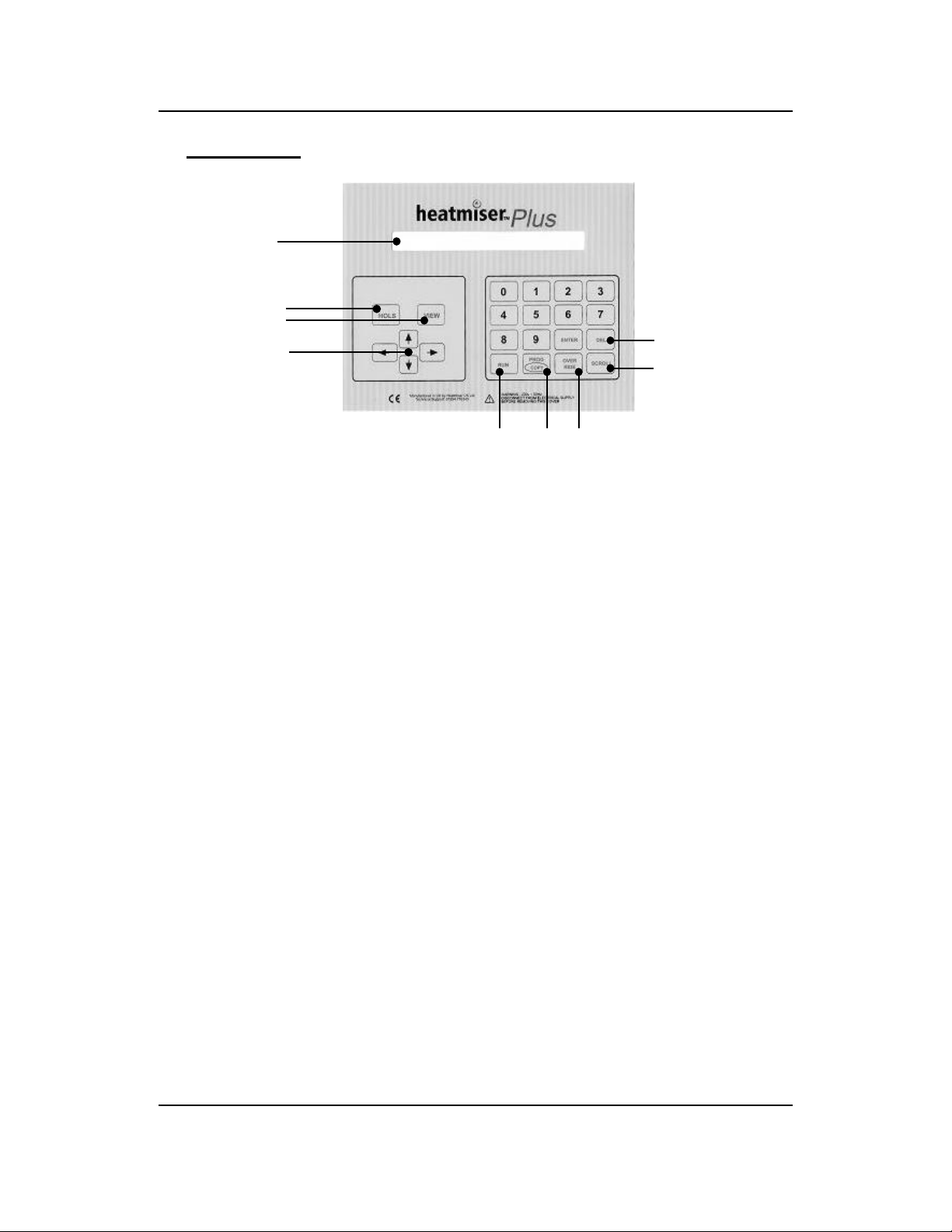
Keypad Layout
Back Lit LCD
HOLS Button
VIEW Button
Up/Down
Left/Right
Arrow Keys
Run Prog/ Override
Key Copy
Back Lit LCD - The Heatmiser Plus has a 40*2 character back lit LCD. The back light is
activated when any key is pressed and remains active for 5 minutes after the last key press.
Delete Key
Scroll forward key
HOLS Button - The Heatmiser Plus features a HOLS button which allows the user to put the
control in to a holiday condition. This will put all zones in to a night setback condition. To
switch the Holiday condition off repeat the process.
VIEW Button - Pressing the VIEW button on the Heatmiser Plus allows the user to see the
following information per zone. Day Maximum/Minimum Temperature, Night Minimum
Temperature, Occupancy On Time, Reached Set Point, Maximum Preheat, Rate Of Change,
Hours Run.
Up/Down Arrow Keys - The Up/Down arrow keys allow the user to increase/decrease the
temperature temporarily for the current switching period only. At the start of the next
switching period, the temperature will revert back to the programmed Day temperature.
Up/Down Arrow Keys-The Left/Right arrow keys allow the user to scroll left or right
through the different zones on the system.
Run Key - The Run key is used at the end of programming to put the control in to the
normal RUN mode.
Program / Copy - The program/copy button is a dual purpose button and is used to enter
the programming section of the control and to copy the switching times from one day to the
next.
Override-Used to override the heating on/off. Used in conditions where the building is
being used outside of the programmed switching times.
Delete - The Delete key is used to correct any mistakes made during programming.
Scroll-The scroll key is used to scroll between the different zones screens. The zone screen
shows the relevant information for the particular zone, including actual and required
temperature and relay status.
Revision 2 18th August 2002 Page 4 of 38
Page 5

Heatmiser Plus User Manual
Standard Terms
Self Learning Optimisation is a system whereby the Heatmiser control will automatically
calculate the start up time to ensure the building is up to temperature for the programmed
switching time. It does this by monitoring the internal temperature readings, so that for example
in milder weather conditions heat up times are reduced - thus saving energy.
Compensation is a system whereby the Heatmiser monitors the Internal and External
temperatures and regulates the flow temperature according to the preset slope setting in the
control. By monitoring the internal and external temperatures the Heatmiser can calculate the
flow temperature needed to maintain the programmed room temperatures.
Pump Overrun To help dissipate the heat from the boiler, a pump overrun time can be set in
the Heatmiser Plus. When enabled, the pump will run on for a number of minutes
(programmable) after the zone has switched off.
Boiler Sequencing The Heatmiser Plus can sequence up to 6 modular boilers providing the
most efficient way of heating a building.
Alarm/Override Inputs The Heatmiser Plus has 8 inputs which can be used as zone overrides
or alarm inputs. When set as an override, the zone will override on/off when the input is made or
broken. The alarm input mode allows the Heatmiser to flash on screen an alarm message when
the input is made.
Preheat is the number of hours the control can come on before the programmed switching time
(when in optimising mode) This is set under the Engineers code and can be set to no more than 8
hours.
Rate of change is the time it takes to raise the building 1’C. The factory default for this setting
is 20 minutes but the control will automatically adjust this according to the fabric of the building.
Override Using the override button on the Heatmiser Keypad allows the user to override the
zone for a selected number of hours, to allow for unscheduled use of the system. A maximum can
be set to stop users entering long override periods.
Switching period status:
• Day is when the control is being controlled to an actual switching time. (For example
Between 07.00—18.00 the control would be in a DAY condition. Outside of these hours the
control would be in a NIGHT condition.
• Night is when no switching times have been programmed. At these times the control is set
back to the NIGHT temperature.
Revision 2 18th August 2002 Page 5 of 38
Page 6
THEHEATMISERPLUSTECHNICALSHEET
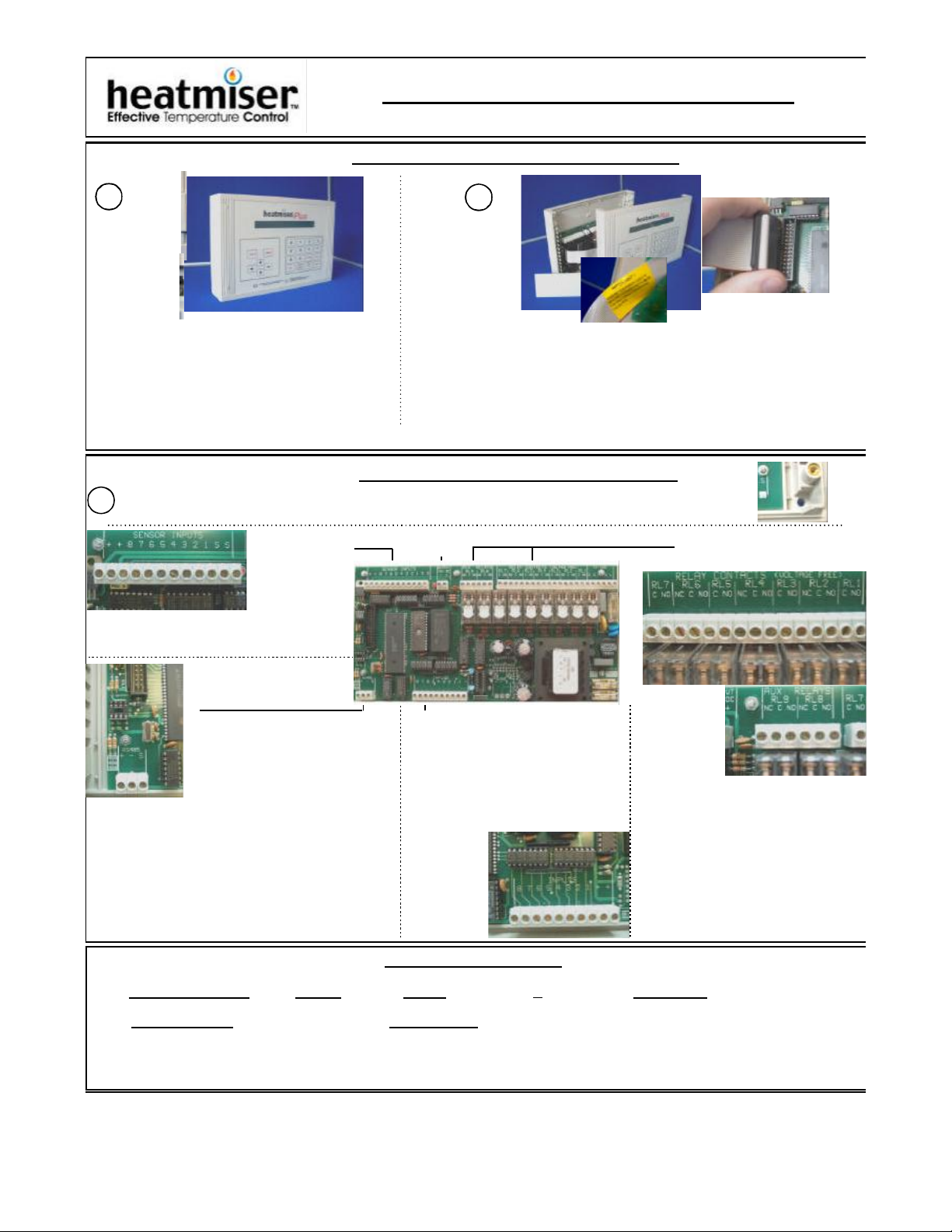
OpeningtheHeatmiser
1
ToopentheHeatmiser,firstlyrelease
theclipsfromthefourcornersofthe
enclosure.
Thiswillrevealfourposiscrews.
2
WhenyouopentheHeatmiser,removetheendpanelfirst.
YouwillnoticearibboncableconnectingtheLCDboardtothe
bottomcircuitboard.
Carefully,unplugtheribbonfromthebottomboardandputthe
LCDtooneside.
FittingtheHeatmiser
TheHeatmiserisfittedtothewallusingthefourmountingholes,oneineachcorneroftheenclosure.
1
SensorInputs
TheHeatmiser
Plushas8
sensorinputs.
TheSand+terminalarecommontoall
sensorinputs.1-8denotesthezone.
12vOutput
RelayOutputs
RS485Connection
TheHeatmiserPlushasthe
networkingcapability.
Byconnectingacommunications
boxtotheRS485terminalthe
HeatmiserPluscanbelinkedviaamodemtoa
remotesite,orcanbewiredbacktoaWindows
95/98PCtoallowcentralcontroloftheentire
heatingsystem.Acommunicationschipisalso
required,thisispluggedintothesocketmarked
IC16.Whenfittingthechip,thenotchonthe
socketshouldbealignedwiththatonthechip.
Inputs
canbeusedasfollows.
Inputs1-6areforzones1-6
remoteoverride,7isfor
Summer
Modeand8
isfor
Holiday
mode.
TheHeatmiserPlushas
8Voltfreeinputsand
The
Heatmiser
Plushas
twobanks
ofoutput
relayterminals.Intotalthereare
9voltagefreerelays.Relays8&9
areAuxiliaryrelaysandareboth
changeoverrelays.
Thereare5NormallyOpen/Normally
Closedrelaysand4NormallyOpen
Relays
Allratedat3amps.
TechnicalSpecification
EnclosureMaterial -ABS Weight -1.7kg Supply -220-240vAC+10%50Hz Dimensions -158x62x260mm
Batteryback-up -10yearbatteryback-up RelayOutputs -9VoltageFreeRelays.3amp250vAC(Resistive)
Relays2,4,6,8,9havechangeovercontacts.TheothersareNormallyOpen
Page 7
Heatmiser Plus User Manual
Normal RUN Mode
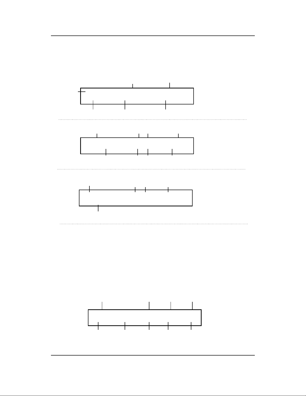
The Heatmiser Plus has two different types of RUN mode screens. The first is the Time/Date
screen and the other is the Zone information screen. The Zone information screen layout will
change depending on how the zone is setup.
Time Input Status
Day/Date THU 15-08-02 11.58.34 INPUTS: CLEAR Time/Date Screen
WEEK 34 EXT:17 COMMS: 0
Week Number External Temperature Communication status (PC Only)
Temperature
Zone Title Required / Actual Zone Status (Day or Night)
1 HEATING ZONE NO1 (20): 21 STATUS DAY Zone Information
OUTPUT OFF FLOW (32): 35 PUMP ON 18 Compensation Screen
Relay Status Flow Temperature Pump Overrun status
Required / Actual
Zone Title Temp - Required/Actual Zone Status
HEATING ZONE NO1 (20): 18 STATUS DAY Zone information
OUTPUT ON Optimiser Screen
Relay Status
These are the functions available to you in the Normal RUN Mode.
Scroll Screens Using the scroll key you are able to scroll through the scroll screens from
zones 1 through to 7. Using the left or right arrow keys you are able to cycle through the Zone
information screens in any order.
Increasing/Decreasing the room temperature temporarily
To alter the required temperature temporarily you can use the Up and Down arrow keys.
Viewing technical screen
Pressing the VIEW button on the zone you want more information will present the following
screen.
Zone Title Day Max Temp Day Min Temp Night Min Temp
1 HEATING ZONE NO 1 DMAX20 DMIN18 NMIN 15
OOT07.30 RSP08.30 MPH03 ROC20 HR03.00
Occupancy Reached Set Maximum Rate Hours Run
On Time Point Preheat of change
Revision 2 18th August 2002 Page 7 of 38
Page 8

Heatmiser Plus User Manual
Service Mode
Pressing the program button and then pressing the override button four times will put the
Heatmiser Plus into Service Mode. This activates all relay outputs for 1 hour. Pressing the same
sequence again will cancel this function.
Important Note: When you are using power open/power closed valves it is important that you
observe the wiring instructions at the back of this manual. Failure to observe these
instructions may result in damage to the valve when using the Service mode.
Override
The Heatmiser Plus has an override function. This allows the user to override the programmed
switching times to allow for unscheduled use of the system.
To override the system first make a note of the zone you wish to override.
• Press OVERRIDE and select the PLEASE ENTER THE NUMBER OF
zone you wish to override. YOU WISH TO OVERRIDE (1-7): 01
• Now you are prompted to Do you want to override the zone
select whether you wish to 1> ON (Day Temp) or 2 OFF (Night Temp)
override the zone On or Off.
• You must now program the PLEASE ENTER THE REQUIRED OVERRIDE
the number of hours you wish PERIOD (08 HOURS MAXIMUM) : 00
to override the system.
• When you have finished 1 HEATING ZONE NO1 (20):18 STATUS OR D01
programming the override, you OUTPUT ON
will see on an indication on the
display. In this case the display shows STATUS OR D01, which means the system has been
overridden to a DAY condition for 1 hour. N01 would be shown to indicate the system has
been overridden to a night condition.
To cancel an override. Repeat the steps outlined above, reducing the number of hours to 00.
Holiday Function (On the keypad)
The Heatmiser Plus has a holiday button on the keypad which can be used to shut the entire
system off.
ARE YOU SURE YOU WANT TO SWITCH ON
• Pressing the HOLS button HOLIDAY MODE < PRESS ENTER FOR YES>
will display the screen shown.
Pressing ENTER will activate the holiday function and will put all zones enabled to accept
the holiday function in to a Night setback condition.
• Pressing any other key will cancel this operation.
• To cancel the Holiday condition repeat the steps outlined above.
Revision 2 18th August 2002 Page 8 of 38
Page 9

Heatmiser Plus User Manual
Normal RUN Mode Screen
DATA- Programming the DAY temperatures and Switching times.
From the Normal Run mode screen pressing the PROG key will display the screen below.
• At this point you are prompted A SECURITY CODE IS REQUIRED TO PROGRAM
to enter your user code. This will THIS UNIT. PLEASE ENTER THE CODE:
be a 4 digit code.
You must press enter when you have entered your four digit code.
As a factory default the User code is set to 0000. It is recommended that you change
this code after installation.
• Should you have mis-typed or ** THE CODE YOU ENTERED **
forgotten your user code an ** WAS INCORRECT**
error screen will be displayed for
5 seconds. You should contact your installer where you have forgotten your user code.
• Afterentering your user code 1> DATA 2>TIME 3> CODE 4>HOLIDAYS
you will be prompted with the Press <1-4> for required option.
following screen. You should
select option 1 for DATA to program the switching times and temperatures.
• As the Heatmiser Plus is multi- PLEASE ENTER THE NUMBER OF THE ZONE
zone, you are first prompted YOU WISH TO ALTER. <1-7>
to enter the number of the zone
you wish to alter.
ENTER THE REQUIRED ‘DAY’ TEMPERATURE
• We are now prompted to enter (OCCUPANCY PERIOD E.G 20 C) : 20
the required DAY temperature.
This is the temperature the control will maintain during the programmed switching times.
Use the number keys to enter the required DAY temperature.
• We are now prompted to enter ENTER THE REQUIRED NIGHT TEMPERATURE
the required NIGHT temperature. (SETBACK OR FROST E.G 04 C) :04
This is the temperature the control
will maintain outside of the programmed switching time. This setting is normally used to
give frost protection.
Note ! - At any time when programming the Heatmiser, you are able to use the ENTER key to
accept the programmed setting and continue or the RUN Key to accept the programmed setting
and return to the DATA menu.
Revision 2 18th August 2002 Page 9 of 38
Page 10
Heatmiser Plus User Manual
DATA- Programming the DAY temperatures and Switching times. (Continued)
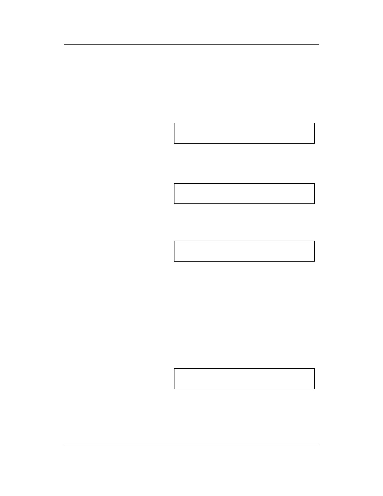
The Heatmiser Plus has 4 switching periods available per day per zone. It is important to use 24
hour clock notation when programming the Heatmiser Plus. You do not need to program all of
the 4 switching periods simply leave the unused periods at 00.00.
When you have programmed the DAY and NIGHT temperature settings you are prompted to
program the required switching times for the selected zone.
• You will be prompted with the Enter switching times for period 1 Mon
following screen. START: 08.00 END 17.00
At this screen you should enter
the required Start time, for example 08.00 and then press Enter. Then you should enter
the End time, eg 17.00.
• When you are happy with the programmed switching time press Enter to accept it and to
continue programming.
• You are able to program the times Enter switching times for period 2 Mon
for period 2 Monday. START: 22.00 END 23.50
Enter the required time in the
same way as you programmed the switching time for period 1.
• Repeat for periods 3-4
• You are now prompted to enter Enter switching times for period 1 Tue
the switching times for Tuesday. START : 08.00 END 17.00
• At this point you can enter the
switching times in the same way as for Monday, or you may press the COPY button which
will copy all of the switching times from Monday to Tuesday. The control will then display
Wednesday Period 1.
• Repeat for the week.
Setting the current Time/Date
The Heatmiser Plus has an internal timer which is extremely accurate. Furthermore, the
Heatmiser Plus features automatic GMT ( Greenwich Mean Time ) correction.
To correct the TIME/DATE setting follow the steps outlined below;
• Press the PROG key and Enter the USER code.
• Select option 2 for TIME.
• You will be presented with the The clock is now set at : 13.37
the following screen. PLEASE ENTER A NEW TIME:
• Enter the correct time using 24 hour clock notation.
Revision 2 18th August 2002 Page 10 of 38
Page 11

Heatmiser Plus User Manual
Setting the current Time/Date (Continued)
• We are now prompted to enter The date is now set at : 19-08-02
the date in DD-MM-YY format. PLEASE ENTER A NEW DATE:
• Enter a new date and press ENTER when you are happy with the programmed setting.
• Press RUN to return to the Normal RUN Mode.
Changing the USER code
• To change the USER Code, press PROG and enter the user security code.
• Then press ENTER
• Select 3 for code.
• Now enter a new 4 digit code The old USER security code was : 0000
and press ENTER when complete. PLEASE ENTER A NEW CODE (4 DIGITS) :
• Press RUN to return to the Normal RUN mode.
Programming the Holiday periods.
The Heatmiser has 5 holiday periods available which can be used to program the holiday periods
for the year.
• To program a holiday period press PROG and enter the USER code.
• Then select 4 for holidays.
• You are now presented with the PLEASE ENTER HOLIDAY PERIOD NUMBER 1
screen for holiday period 1 START DATE : 00-00-00 LENGTH : 00
• To program the holiday period enter the start date followed by the number of days the
heating should be off for.
Important Notes
1.The holiday period should be entered in DD-MM-YY format.
2.In holiday mode, the Heatmiser Plus will maintain the NIGHT setback temperature.
3.When programming holiday periods you must program forthcoming holidays. You cannot
enter a holiday date which has passed. If you do this the control will not recognise the
holiday and the Heatmiser will work to the programmed switching times.
3.Should you wish to delete a holiday period which is currently running, you will need to
perform the following steps;
• Press the HOLS button on the Heatmiser Plus front panel.
• Press the ENTER key to turn the holiday function ON
• Press the HOLS button on the Heatmiser Plus front panel again.
• Press the HOLS button to turn the holiday function OFF.
Revision 2 18th August 2002 Page 11 of 38
Page 12

Heatmiser Plus User Manual
Configuring the system
The Heatmiser Plus is our multipurpose control and has a wide number of configurations
available. This section aims to guide you through the configuration process.
To configure the Heatmiser Plus follow the steps below;
• Press PROG and enter the configuration code which will be located on the reverse side of
the Heatmiser keypad or alternatively on the Heatmiser enclosure back box.
• When you have entered the code you will be presented with the following screen.
• At this point you are able to begin 1) SYSTEM CONFIG 2) SYSTEM RESET
the configuration process or you !! WARNING!! Read instructions first !!
are able to reset the system back
to the factory defaults.
SYSTEM CONFIG.
• Press 1 for Config
• You are now presented with 5 possible zone types for Zone 1. These zone types are
explained as follows.
<1> OPT <02> COMP <03> HILO <04> BS FIXED
<05>BS VARIABLE ZONE 1 TYPE ? :
1.OPT = Optimiser. The control will automatically calculate the start up time to ensure the
building is warm by the start of the programmed switching time. It does this by monitoring
the internal temperature and adjusting the amount of preheat required.
2.COMP = Compensator. The control will automatically calculate the flow temperature
required to maintain room temperature. By monitoring the internal and external sensor
temperatures, the flow temperature can be increased or decreased to suit demand. This
calculation is worked from a slope factor which can be altered on-screen. The slope factor
is set to 06 as a factory default. In this setting for every 1 degree rise in external
temperature the flow temperature will be decreased by 3 degrees. If the slope factor
is increased to 07 - for every 1 degree rise in external the flow will be decreased by 4
degrees.
3.HILO = This setting gives control over high/low heaters. A high/low differential setting can
be set which is the number of degrees below the required temperature that the high flame
will switch off.
4.BS FIXED = This option is used when you are sequencing boilers and you have a
hot water cylinder or more than one heating zone on the boiler circuit. The control allows
you to enter a fixed flow temperature.
5.BS(VARIABLE) = This option is used when you have only one heating zone on the boiler
circuit and no hot water cylinder. This option gives you the setting to control the minimum
and maximum flow settings as well as the slope factor which is mentioned under
Compensation above.
Revision 2 18th August 2002 Page 12 of 38
Page 13
Heatmiser Plus User Manual
Configuring the system (Continued)
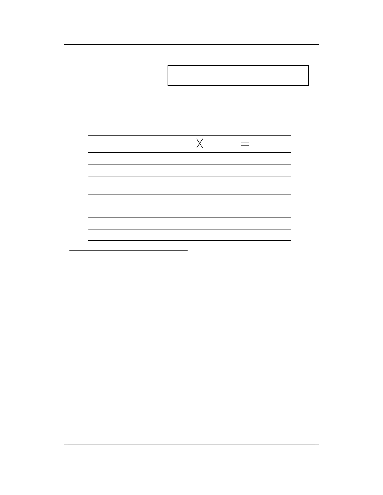
• We must now select the zone <1> OPT <02> COMP <03> HILO <04> BS FIXED
type for zone 1. <05>BS VARIABLE ZONE 1 TYPE ? :
Note: If compensation or boiler sequencing is required on the system
these must be setup before any optimised zones.
The Heatmiser Plus has 9 relays which can be used for various applications depending on the
configuration selected. To calculate the number of relays required for your system observe the
following table.
Number of
Zones/boilers
No of relays
Required
Total relays
Required
Boiler Sequencing 1
Compensated zones 3
Optimised zones
Including hot water, any timed
zones etc
1
HiLo Zones 2
Pump Overrun 1
Total =
Example System = Total number of relays: 9
For a two boiler sequencer with pump overrun and 2 compensated zones.
Once you have selected the zone type for each zone you will be prompted to answer the
following questions.
Entering the number of zones.
You should now enter the total number of zones on the system.
Entering the functions for the OUTS.
*This section can only be used if relays 8&9 are not already used*
You are now able to program how relays 8&9 will operate. You have three options as described
below;
<00> This uses the Aux. Relays as RL8 & RL9 and they are therefore configured as
for relays 1-7.
<01> This uses Aux. Relays as auto pump changeover outputs in conjunction with inputs 4 & 6.
These inputs are used to give auto pump changeover on failure and by bringing the following
terminals will changeover the pumps until midnight the next Sunday providing the fault has been
cleared.
Making Input 4 gives pump changeover on relay 9.
Making Input 6 gives pump changeover on relay 8.
Important Note: When you are using the Pump changeover facility it disables the use of the
remote overrides inputs for inputs 3 through to 6.
<02> Auxiliary relays are used as follows
Relay 8- Any zone calling for heat will make this output active.
Revision 2 18th August 2002 Page 13 of 38
Page 14
Heatmiser Plus User Manual
Configuring the system (Continued)
Sensor Averaging…
The Heatmiser Plus has the facility to average two temperature readings. For example you may
have a large heating zone which would be controlled better if two temperature sensors were
Installed in the zone and the average reading taken. To set this up follow the steps below;
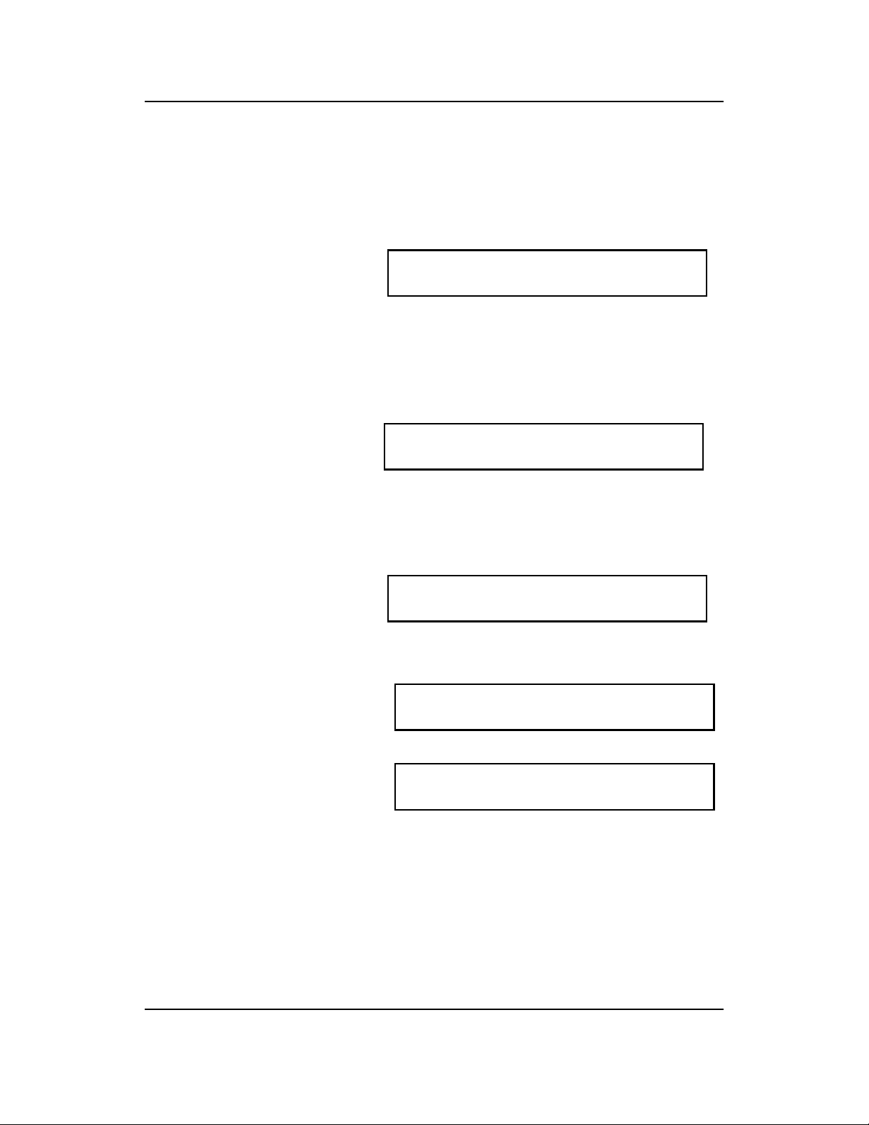
• Enter the number of the sensor Enter the number of the sensor you want
you wish to average with sensor to average with S7: (00=NONE) :00
7. The default is 00 which
disables this function. When you are using the averaging facility you calibrate each sensor
as explained in the Calibration section. You will only see the averaged temperature reading
on the zone screen.
Frost Setting for Holiday Switch…
This function allows you to set a temperature which will be used whenever the holiday switch is
made. Setting this to 00 disables this function and the night setback temperature will be
maintained.
Enter the Frost Setting for the external
Holiday switch (00=Night Temp.) :00
Outstation Number
This setting is only used when the control is part of a computer network. In this case each control
must have an individual outstation number. The factory default is 00 which disables the
communications
Enter the Outstation Number for this unit
(00= No communications) : 00
Resetting the system
• From the Config Menu screen 1) SYSTEM CONFIG 2) SYSTEM RESET
select 2 for System Reset. !! WARNING!! Read instructions first !!
• You are then prompted to press !!WARNING !! THIS OPTION WILL CLEAR ALL
DELETE to continue. MEMORY. PRESS (DEL)ETE TO CONTINUE
• At this point you should press RUN where you will notice the relays will click in and then
out which indicates the memory and all configurations have been cleared.
YOU SHOULD BE AWARE THAT THIS OPTION CLEARS THE MEMORY AND REVERTS THE
HEATMISER BACK TO ALL FACTORY DEFAUT SETTINGS.
THIS OPTION SHOULD ONLY BE USED BY EXPERIENCED USERS AND BY THOSE WHO ARE
FAMILIAR WITH CONFIGURING THE HEATMISER.
Revision 2 18th August 2002 Page 14 of 38
Page 15

Heatmiser Plus User Manual
Engineer Setup
! What you need prior to starting the setup procedure !
• The configuration and Engineers code
(These will be found stuck to the reverse side of the keypad)
• The type of zone and total number of zones on the system.
• The total number of alarms/override inputs on the system.
• An accurate reading of the actual temperature in each zone taken from a digital
thermometer.
• The zone title for each zone if needed.
• The switching times for each zone.
• The required DAY and NIGHT temperatures for each zone.
•
• Press PROG A SECURITY CODE IS REQUIRED TO PROGRAM
• Enter the engineer code and THIS UNIT. Please enter the code:
press ENTER. (The engineers
code can be found inside the control either on the reverse side of the keypad or on the
back panel above the circuit board.
• When you have gained access to the engineer section you will be presented with the
following screen.
1> SETUP 2> TITLES 3>CODE 4> MONITOR
5> HOURS RUN 6> CLEAR MONITOR 7> INPUTS
1. SETUP = Under this section you are able to do the following.
• Calibrate the sensors.
• Set the maximum override time.
• Enter the temperature offset “upper” limit.
• Enter the temperature offset “lower” limit.
• Individual zone configuration.
2. TITLES = Under this section you are able to do the following.
• Program the zone titles.
• Program the alarm titles.
• Program the relay titles.
3. CODE = Under this section you are able to do the following.
• Change the USER code.
4. MONITOR = Under this section you can view the following.
• The temperature log for the past 24 hours.
5. HOURS RUN = Under this section you can view the following.
• The hours run log for the past 4 weeks.
6. CLEAR MONITOR = Under this section you can do the following.
• Clear the logging and alarm memory.
7. INPUTS = Under this section you can do the following.
• Enable/Disable the Holiday/Summer input function
• Enter the type of inputs required, Pulse or Fixed.
• Select the number of zone override required on the system.
Revision 2 18th August 2002 Page 15 of 38
Page 16

Heatmiser Plus User Manual
Engineer Setup
1.Setup > Calibration
The Heatmiser Plus has eight sensor inputs and these should be calibrated after installation of the
system.
To calibrate the Heatmiser sensors you firstly need a temperature reading from a digital
thermometer, for each zone or pipe being monitored.
From this reading we are now able to calibrate each sensor on the system.
To calibrate the sensors, follow the steps below;
• Take the actual reading from your Enter calibration setting number 1 <10>
thermometer and the reading THE SENSOR IS NOW READING : 18
from the Heatmiser sensor.
• As an example, your thermometer reading is 20 and the Heatmiser sensor is 18 with a
calibration of 10. (The calibration figure is the two digits in the brackets in the above
screen) In this example there is an error of 02 degrees, however as the Heatmiser works
in 1/2 degree steps the calibration needs to be increased by 04. Therefore the calibration
figure in this example should be 14.
• The process outlined above should be repeated for all sensors on the system. Use the
ENTER key to advance through the different calibration screens.
1.Setup > Maximum override time
To avoid excessive use of the Override button it is recommended that a maximum override time
is programmed in to the control.
• Enter the maximum override period Enter the maximum override you want from
here. the override button. : <00=DISABLED>: 08
• The factory default setting is 08. Should you wish to disable the use of the override button
enter 00 as the override time.
1. Setup > Offset UPPER limit
As the Heatmiser Plus has Up/Down arrow keys for increasing or decreasing the required
temperature for the current programmed switching time. It is recommended that limitations are
set on the use of these buttons.
• Enter the maximum number of Enter the temperature offset upper limit
degrees you want the user to be you want for the UP button. :02
able to increase the temperature
by use of the UP arrow key.
Revision 2 18th August 2002 Page 16 of 38
Page 17

Heatmiser Plus User Manual
Engineer Setup
1. Setup > Offset LOWER limit
• Enter the number of maximum Enter the temperature offset lower limit
degrees you want the user to be you want for the DOWN button. :02
able to decrease the temperature
by use of the DOWN arrow key.
After you have configured the system wide settings, you are then prompted to program the
individual zones settings as described below. You first need to select the zone you wish to setup.
Setup > Individual zone setup
ZONE TYPE = BOILER SEQUENCER FIXED)
• You must now select the summer SUMMER FUNCTION. (03)NONE (02)EXTERNAL
input function for this zone. If you (01) INTERNAL (00)INT.EXT :00
want to disable the summer input
(number 7) for this zone enter 01 here.
• Enter the required temperature Enter the external temperature that
that you would like the heating you would like the heating off at: 19
off at. Should the external
temperature rise above the setting programmed the system will switch to night setback
temperature.
• We now need to select the zone <00> OPT(LEARNING) <01>TIMER <02> OPT FIX
type for zone 1. <03> OPT-TIME <04> VENT OPTION? :00
00 = Optimiser mode only
Automatically adjusts the start up time so that the building is warm for the start of the
programmed switching period. The Heatmiser will adjust the rate of change and preheat as
the Heatmiser learns the system.
01 = Timer mode only.
The zone works to the switching times only.
02 = Opt (Fixed)
This is a fixed optimiser. Working from the programmed rate of change and preheat the
control will calculate the start-up time. The rate of change and preheat is not altered by
the system.
03 = Opt (Time)
This is the optimiser timer function. The control will use the internal sensor only to
calculate the start-up time, based on the preheat and rate of change.
The internal sensor is ignored once the switching time has been reached.
Revision 2 18th August 2002 Page 17 of 38
Page 18
Heatmiser Plus User Manual
Engineer Setup
Setup > Individual zone setup (BOILER SEQUENCER FIXED)…. Continued
04 = VENT. Not used on this type of system.
Fixed flow...
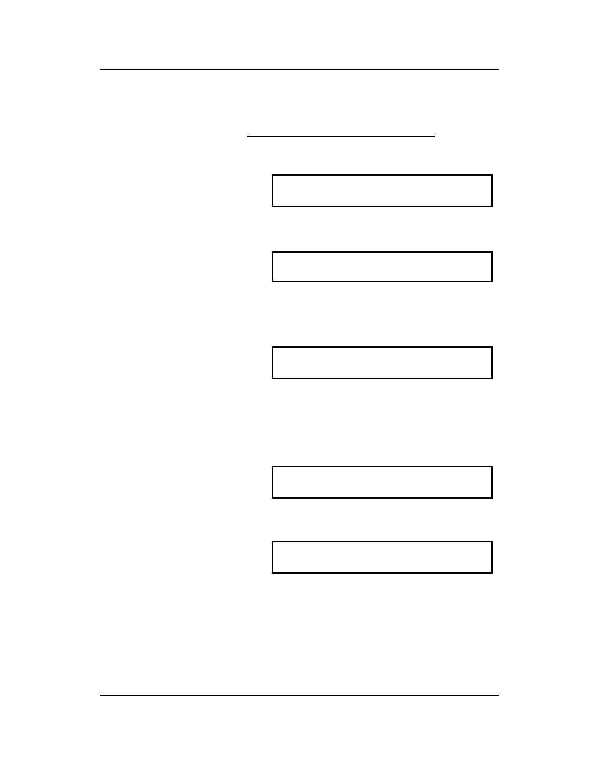
• We must now program the fixed Enter the FIXED FLOW temperature for
flow temperature for the boiler the boiler sequencer. (eg. 75) : 00
sequencer. The recommended
flow temperature is between 70C - 80C.
Maximum preheat… (This screen will not be displayed on timer zones)
• We must now program the Enter the MAXIMUM PREHEAT HOURS you want
maximum preheat allowed for this for the optimiser (eg. 03 hours) : 03
zone. The factory default is 03.
This is the maximum number of hours the control may come on before the programmed
switching time.
Rate of change… (This screen will not be displayed on timer zones)
• We must now program the rate Enter the RATE OF CHANGE setting for the
of change for this zone. Optimiser( 00 = No optimiser ) : 20
This is the number of minutes it
takes to raise the building by 1 degree.
If the zone is setup as a Opt or an Opt-Time this figure will automatically change as
the control learns the system. If the zone is setup as an Opt-Fixed zone this setting
will not change.
Flow frost protection…
• We must now program the flow Enter the flow frost protection setting
frost protection setting for this for this zone (e.g. 08 c) :08
zone. This setting is only used
when there is a flow sensor on the system. The default setting for this is 08.
Pump Overrun…
• A pump overrun time can now be Enter the PUMP OVERRUN TIME required
programmed in to the system. : 00
The recommended time for the
pump overrun is 20 minutes.
A pump overrun is not set when each boiler has its own pump.
Revision 2 18th August 2002 Page 18 of 38
Page 19
Heatmiser Plus User Manual
Engineer Setup
Setup > Individual zone setup (BOILER SEQUENCER FIXED)…. Continued
Boiler On Delay...
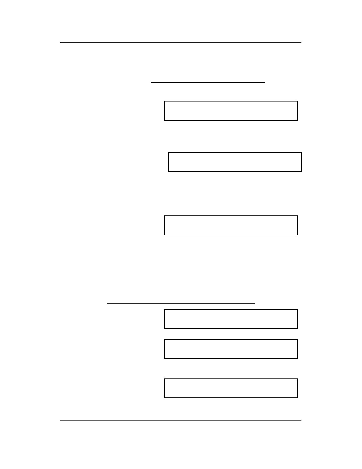
• This is the time delay between ENTER THE BOILER ON TIME DELAY REQUIRED
boilers switching ON when the FOR THE BOILER SEQUENCER: 48
flow is under temperature.
Every 1 entered gives a delay of 5 seconds. Therefore entering 48 will give a delay of 4
minutes.
Boiler Off Delay…
• This is the time delay between ENTER THE BOILER OFF TIME DELAY REQUIRED
boilers switching OFF when the FOR THE BOILER SEQUENCER: 20
flow is above temperature.
Every 1 entered gives a delay of 5 seconds. Therefore entering 20 will give a delay of 1
minute.
Reverse the lead and lag boilers…
• To even the wear between the
boilers installed, you are able Do you want the boilers to reverse every
to program whether the boilers 7 days <01> or fixed <00> : 00
should rotate the lead and lag
boiler every 7 days.
00 disables this feature. 01 activates this feature.
• At this point you are returned to the Setup menu where you can continue to configure the
other zones or you may press RUN to put the control in to the Normal RUN mode.
Setup > Individual zone setup
ZONE TYPE = BOILER SEQUENCER VARIABLE)
• You must now select the summer SUMMER FUNCTION. (03)NONE (02)EXTERNAL
input function for this zone. If you (01) INTERNAL (00)INT.EXT :00
want to disable the summer input
(number 7) for this zone enter 01 here.
• Enter the required temperature Enter the external temperature that
that you would like the heating you would like the heating off at: 19
off at. Should the external
temperature rise above the setting programmed, the system will switch to the night set
back temperature.
• We now need to select the zone <00> OPT(LEARNING) <01>TIMER <02> OPT FIX
type for zone 1. <03> OPT-TIME <04> VENT OPTION? :00
See options on page ??. Only options 00, 01, 02, 03 apply to this type of configuration
Revision 2 18th August 2002 Page 19 of 38
Page 20
Heatmiser Plus User Manual
Engineer Setup
Setup > Individual zone setup
(BOILER SEQUENCER VARIABLE) Continued
Maximum preheat… (This screen will not be displayed on timer zones)
• We must now program the Enter the MAXIMUM PREHEAT HOURS you want
maximum preheat allowed for this for the optimiser (eg. 03 hours) : 03
zone. The factory default is 03.
This is the maximum number of hours the control may come on before the programmed
switching time.
Rate of change… (This screen will not be displayed on timer zones)
• We must now program the rate Enter the RATE OF CHANGE setting for the
of change for this zone. Optimiser( 00 = No optimiser ) : 20
This is the number of minutes it
takes to raise the building by 1 degree.
If the zone is setup as a Opt or an Opt-Time this figure will automatically change as
the control learns the system. If the zone is setup as an Opt-Fixed zone this setting
will not change.
Flow frost protection…
• We must now program the flow Enter the flow frost protection setting
frost protection setting for this for this zone (e.g. 08 c) :08
zone. This setting is only used
when there is a flow sensor on the system. The default setting for this is 08.
Compensation slope…
• We are now prompted to enter Enter the COMPENSATION SLOPE FACTOR
the slope factor. The slope factor (06 = Normal) :06
determines how the flow
temperature changes in relation to the external temperature. The normal setting is 06
which means that for every 1 degree rise in external temperature the flow temperature will
be decreased by 3 degrees. A slope of 7 means for every 1 degree rise in external
temperature the flow will be reduced by 4 degrees.
Minimum flow temperature …
• We are now able to set the Enter the MINIMUM FLOW temperature
minimum flow temperature. for this zone: 00
Compensating direct on the boiler = You should contact the boiler manufacturer for this setting.
Compensating via a valve = You should enter 00 as no minimum flow temp is required.
Revision 2 18th August 2002 Page 20 of 38
Page 21
Heatmiser Plus User Manual
Engineer Setup
Setup > Individual zone setup
(BOILER SEQUENCER VARIABLE) Continued
Maximum flow temperature …
• We are now able to set the Enter the MAXIMUM FLOW temperature
maximum flow temperature. for this zone: 00
Compensating direct on the boiler = You should contact the boiler manufacturer for this setting.
Compensating via a valve = You should enter 00 as no minimum flow temp is required.
PumpOverrun…
• A pump overrun time can now be Enter the PUMP OVERRUN TIME required
programmed in to the system. : 00
The recommended time for the
pump overrun is 20 minutes.
A pump overrun is not set when each boiler has its own pump.
Boiler On Delay...
• This is the time delay between ENTER THE BOILER ON TIME DELAY REQUIRED
boilers switching ON when the FOR THE BOILER SEQUENCER: 48
flow is under temperature.
Every 1 entered gives a delay of 5 seconds. Therefore entering 48 will give a delay of 4
minutes.
Boiler Off Delay…
• This is the time delay between ENTER THE BOILER OFF TIME DELAY REQUIRED
boilers switching OFF when the FOR THE BOILER SEQUENCER: 20
flow is above temperature.
Every 1 entered gives a delay of 5 seconds. Therefore entering 20 will give a delay of 1
minute.
Reverse the lead and lag boilers…
• To even the wear between the
boilers installed, you are able Do you want the boilers to reverse every
to program whether the boilers 7 days <01> or fixed <00> : 00
should rotate the lead and lag
boiler every 7 days.
00 disables this feature. 01 activates this feature.
• Atthis point you are returned to the Setup menu where you can continue to configure the
other zones or you may press RUN to put the control in to the Normal RUN mode.
Revision 2 18th August 2002 Page 21 of 38
Page 22
Heatmiser Plus User Manual
Engineer Setup
Setup > Individual zone setup
COMPENSATOR
You are able to select whether you want DO YOU WANT THIS ZONE TO PUT ZONE 1 IN TO
this zone to put zone 1 in to a DAY A DAY CONDITION. <00> NO <01> :00
condition.
Will be displayed when configuring zones 2-7 only
This is used when zone 1 is a boiler so when any zone calls for heat the boiler fires.
• You must now select the summer SUMMER FUNCTION. (03)NONE (02)EXTERNAL
input function for this zone. If you (01) INTERNAL (00)INT.EXT :00
want to disable the summer input
(number 7) for this zone enter 01 here.
• Enter the required temperature Enter the external temperature that
that you would like the heating you would like the heating off at: 19
off at. Should the external
temperature rise above the setting programmed, the system will switch to night setback
temperature.
• We now need to select the zone <00> OPT(LEARNING) <01>TIMER <02> OPT FIX
type for zone 1. <03> OPT-TIME <04> VENT OPTION? :00
See options on page ??. Only options 00, 01, 02, 03 apply to this type of configuration
Maximum preheat… (This screen will not be displayed on timer zones)
• We must now program the Enter the MAXIMUM PREHEAT HOURS you want
maximum preheat allowed for this for the optimiser (eg. 03 hours) : 03
zone. The factory default is 03.
This is the maximum number of hours the control may come on before the programmed
switching time.
Rate of change… (This screen will not be displayed on timer zones)
• We must now program the rate Enter the RATE OF CHANGE setting for the
of change for this zone. Optimiser( 00 = No optimiser ) : 20
This is the number of minutes it
takes the zone to raise the building by 1 degree.
If the zone is setup as a Opt or an Opt-Time this figure will automatically change as
the control learns the system. If the zone is setup as an Opt-Fixed zone this setting
will not change.
Revision 2 18th August 2002 Page 22 of 38
Page 23

Heatmiser Plus User Manual
Engineer Setup
Setup > Individual zone setup
COMPENSATOR Continued
Compensation slope…
• We are now prompted to enter Enter the COMPENSATION SLOPE FACTOR
the slope factor. The slope factor (06 = Normal) :06
determines how the flow
temperature changes in relation to the external temperature. The normal setting is 06
which means that for every 1 degree rise in external temperature the flow temperature will
be decreased by 3 degrees. A slope of 7 means for every 1 degree rise in external
temperature the flow will be reduced by 4 degrees.
Minimum flow temperature …
• We are now able to set the Enter the MINIMUM FLOW temperature
minimum flow temperature. for this zone: 00
Maximum flow temperature ...
• We are now able to set the Enter the MAXIMUM FLOW temperature
minimum flow temperature. for this zone: 00
ON/OFF or Modulating …
• We are now able to set how IS THIS ZONE GOING TO BE WORKING ON/OFF
the zone will work, either ON/OFF CONTROL<00> OR MODULATING <01> :00
or modulating.
Pulse Time … (ONLY APPLICABLE WHEN THE ZONE IS SET UP TO MODULATE)
• This is the length of the pulse
that the valve will get. As a guide Enter the PULSE TIME that you want to
this can be set to 1/10 the work the valve (1=5 seconds) : 00
valves total travel time.
The recommended pulse time is 03 which is 15 seconds .
Delay Time … (ONLY APPLICABLE WHEN THE ZONE IS SET UP TO MODULATE)
• This is the time between pulses
and as a guide can set to the Enter the DELAY TIME that you want to
total travel time of the valve. work the valve. (1=5 SECONDS) : 00
The recommended delay time is 30 which is 2.5 minutes.
Revision 2 18th August 2002 Page 23 of 38
Page 24

Heatmiser Plus User Manual
Engineer Setup
Setup > Individual zone setup
COMPENSATOR Continued
Hysterysis Value …
• We are now able to set the Enter the HYSTERYSIS VALUE for the
hysterysis value. compensation: 04
This is number of degrees between the load switching in and out for the compensator. For
example, with a setting of 04 and a required flow temperature of 50’C, the load will be switched
in until a flow temperature of 52’C is reached and will then remain off until it drops down to 48’C
when it will switch back on.
Pump Overrun…
• A pump overrun time can now be Enter the PUMP OVERRUN TIME required
programmed in to the system. : 00
The recommended time for the
pump overrun is 20 minutes.
• At this point you are returned to the Setup menu where you can continue to configure the
other zones or you may press RUN to put the control in to the Normal RUN mode.
Revision 2 18th August 2002 Page 24 of 38
Page 25
Heatmiser Plus User Manual
Engineer Setup Setup > Individual zone setup OPTIMISER
• You are able to select whether you DO YOU WANT THIS ZONE TO PUT ZONE 1 IN this
want this zone to put zone 1 in to TO A DAY CONDITION. <00> NO <01> :00
a DAY condition.
This screen will only be displayed when configuring zones 2-7.
• You must now select the summer SUMMER FUNCTION. (03)NONE (02)EXTERNAL
input function for this zone. If you (01) INTERNAL (00)INT.EXT :00
want to disable the summer input
(number 7) for this zone enter 01 here.
• Enter the required temperature Enter the external temperature that
that you would like the heating you would like the heating off at: 19
off at. Should the external
temperature rise above the setting programmed, the system will switch to night setback
temperature.
• We now need to select the zone <00> OPT(LEARNING) <01>TIMER <02> OPT FIX
type for zone 1. <03OPT-TIME <04> VENT OPTION? :02
See options on page ?? Options 0 - 4 can be used on this type of configuration.
Maximum preheat… (This screen will not be displayed on timer zones)
• We must now program the Enter the MAXIMUM PREHEAT HOURS you want
maximum preheat allowed for this for the optimiser (eg. 03 hours) : 03
zone. The factory default is 03.
This is the maximum number of hours the control may come on before the programmed
switching time.
Rate of change… (This screen will not be displayed on timer zones)
• We must now program the rate Enter the RATE OF CHANGE setting for the
of change for this zone. Optimiser( 00 = No optimiser ) : 20
This is the number of minutes it
takes the zone to raise the building by 1 degree.
If the zone is setup as a Opt or an Opt-Time this figure will automatically change as
the control learns the system. If the zone is setup as an Opt-Fixed zone this setting
will not change.
Hot Water Boost…
If this zone is controlling a hot water DO YOU WANT THIS ZONE TO BOOST TO 70’C
cylinder, setting this to <01> will boost MIDNIGHT SUNDAY <01> TIMER <O2>OPT FIX: 00
the temperature to 70’c at midnight
Sunday. If the cylinder does not achieve this temperature within 2 hours, the unit will return to
normal operation.
Note: Using the VIEW button on Monday morning will give information on the temperature the
cylinder achieved and the time it took to get to the maximum temperature.
Revision 2 18th August 2002 Page 25 of 38
Page 26

Heatmiser Plus User Manual
Engineer Setup
Setup > Individual zone setup OPTIMISER continued...
Pump Overrun…
• A pump overrun time can now be Enter the PUMP OVERRUN TIME required
programmed in to the system. : 00
The recommended time for the
pump overrun is 20 minutes.
• At this point you are returned to the Setup menu where you can continue to configure the
other zones or you may press RUN to put the control in to the Normal RUN mode.
Setup > Individual zone setup HILO
You are able to select whether you want DO YOU WANT THIS ZONE TO PUT ZONE 1 IN TO
this zone to put zone 1 in to a DAY A DAY CONDITION. <00> NO <01> :00
condition.
Will be displayed when configuring zones 2-7 only
This is used when zone 1 is a boiler so when any zone calls for heat the boiler fires. However in
this configuration this is not required.
• You must now select the summer SUMMER FUNCTION. (03)NONE (02)EXTERNAL
input function for this zone. If you (01) INTERNAL (00)INT.EXT :00
want to disable the summer input
(number 7) for this zone enter 01 here.
• Enter the required temperature Enter the external temperature that
that you would like the heating you would like the heating off at: 19
off at. Should the external
temperature rise above the setting programmed, the system will switch to night setback
temperature.
• We now need to select the zone <00> OPT(LEARNING) <01>TIMER <02> OPT FIX
type for zone 1. <03> OPT-TIME <04> VENT OPTION? :00
Maximum preheat… (This screen will not be displayed on timer zones)
• We must now program the Enter the MAXIMUM PREHEAT HOURS you want
maximum preheat allowed for this for the optimiser (eg. 03 hours) : 03
zone. The factory default is 03.
This is the maximum number of hours the control may come on before the programmed
switching time.
Revision 2 18th August 2002 Page 26 of 38
Page 27
Heatmiser Plus User Manual
Engineer Setup
Setup > Individual zone setup HILO continued…
Rate of change… (This screen will not be displayed on timer zones)
• We must now program the rate Enter the RATE OF CHANGE setting for the
of change for this zone. Optimiser( 00 = No optimiser ) : 20
This is the number of minutes it
takes the zone to raise the building by 1 degree.
If the zone is setup as a Opt or an Opt-Time this figure will automatically change as
the control learns the system. If the zone is setup as an Opt-Fixed zone this setting
will not change.
• We are now prompted to enter the PLEASE ENTER THE DIFFERENTIAL BETWEEN
High/Low differential setting. HI OUTPUT AND LOW OUTPUT: 04
• This setting is calculated in 1/2 degree steps. Therefore a high/low differential setting of 4
means that the high relay will switch off 2 degrees below the required temperature.
• At this point you are returned to the Setup menu where you can continue to configure the
other zones or you may press RUN to put the control in to the Normal RUN mode.
2. TITLES
• Press the PROG button and enter the Engineers code.
• From the SETUP menu select 2 for TITLES.
• You are now prompted to select the title to alter:
Select the
Required option 1. ZONE TITLE 2. ALARM 3. RELAY TITLE
Press <1-3> for required option
Zone selection PLEASE ENTER THE NUMBER OF THE ZONE
YOU WISH TO ALTER (1-7) : 00
Enter the required characters 0123456789:;<=>?ABCDEFGHIJKLMNOPQRSTUVW
XYZ ENTER THE TITLE HEATING ZONE NO 1
• By using the Left/Right arrow keys to select the required character you can then create the
title required. To advance to the next character use the Enter key.
• To enter a space or to delete a character, select the “space” character to the right of the
letter Z.
• To accept the programmed title press the RUN key.
• Pressthe RUN key to put the control in to the Normal RUN mode.
Revision 2 18th August 2002 Page 27 of 38
Page 28

Heatmiser Plus User Manual
3. CHANGING THE USER CODE
Should the USER code be forgotten you are able to reset it by accessing the
engineers section.
Press PROG, enter the engineers passcode and select 3 for CODE.
THE OLD USER SECURITY CODE WAS : 0000
PLEASE ENTER A NEW CODE(4 DIGITS):
At this point you are able to enter a four digit code. When the code entered is correct press
ENTER.
4. MONITOR
This section logs the temperature and relay status every 15 minutes for the last 24 hours.
TIME RL OFF OFF ON ON OFF OFF OFF OFF
00.00 SEN ?? 62 21 19 26 ?? ?? ??
Pressing ENTER will move you on to the next reading, pressing RUN will return you to the main
menu.
5. HOURS RUN
This section gives the hours run for each relay for the last 4 weeks. The reading on the left is the
current week.
WEEK 04 03 02 01
HOURS RUN 01.14 05.43 06.23 05.21
6. CLEAR MONITOR
This section clears all logging memory.
Revision 2 18th August 2002 Page 28 of 38
Page 29

Heatmiser Plus User Manual
7. OVERRIDE/ALARM INPUTS
On the Heatmiser Plus there are two uses of the inputs. You are able to use them as alarm inputs
or override switches.
• To configure the inputs first press PROG and enter the engineers code.
• Press 7 for inputs
• You must first set whether you DO YOU WANT TO DISABLE THE HOLS AND
would like to disable the holiday SUMMER INPUTS: <00> =NO <01> YES: 00
and summer inputs. Disabling
them allows you to make use of input 7&8 for further alarm/override inputs.
• You must now select whether you ENTER FUNCTION FOR OVERRIDE INPUTS
wish to use a pulse or fixed FIXED <00> PULSE <01> :00
override switch. Fixed means
that for as long as the input is made, the zone will be overridden. Pulse means that when
a
pulse is given to the input the zone will be overridden on. To override the zone off a
further pulse must be given.
• You must now set how many ENTER THE NUMBER OF INPUTS TO USE
remote overrides you want to use FOR THE EXTERNAL ZONE OVERRIDES: 00
on the system. If you have not
disabled the summer and holiday
function you are able to use up to 6 remote overrides. If however you enter only 4, the
remaining unused inputs are allocated as alarm inputs and as such will display an alarm
message should the input be made.
Input configuration - Summer and holiday input enabled.
Inputs 1 - 6 Alarm / Remote override switches
(Configure during setup the number of zone overrides)
Alarm = A message will be displayed on all displays indicating the alarm. The alarm
text can be changed as described under the TITLE heading.
Input 7 - Summer Mode
When the Summer mode input is made, all zones (except those that have the Summer
input disabled. i.e for Hot water zones) will shut down and will be controlled to the
Night setback temperature.
Input 8 - Holiday Mode.
When the Holiday mode input is made, all zones will shut down and will be controlled to
the Night Setback temperature until the holiday input is broken.
Revision 2 18th August 2002 Page 29 of 38
Page 30

Heatmiser Plus User Manual
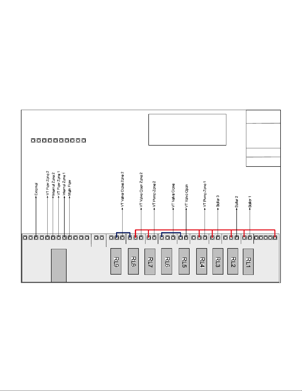
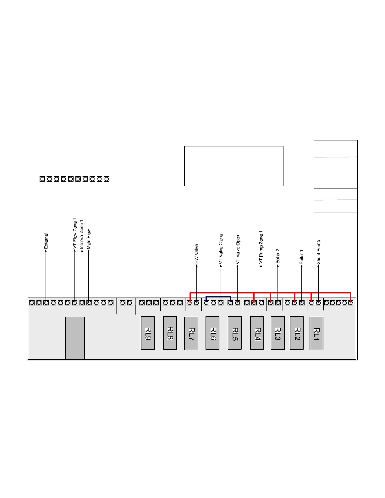
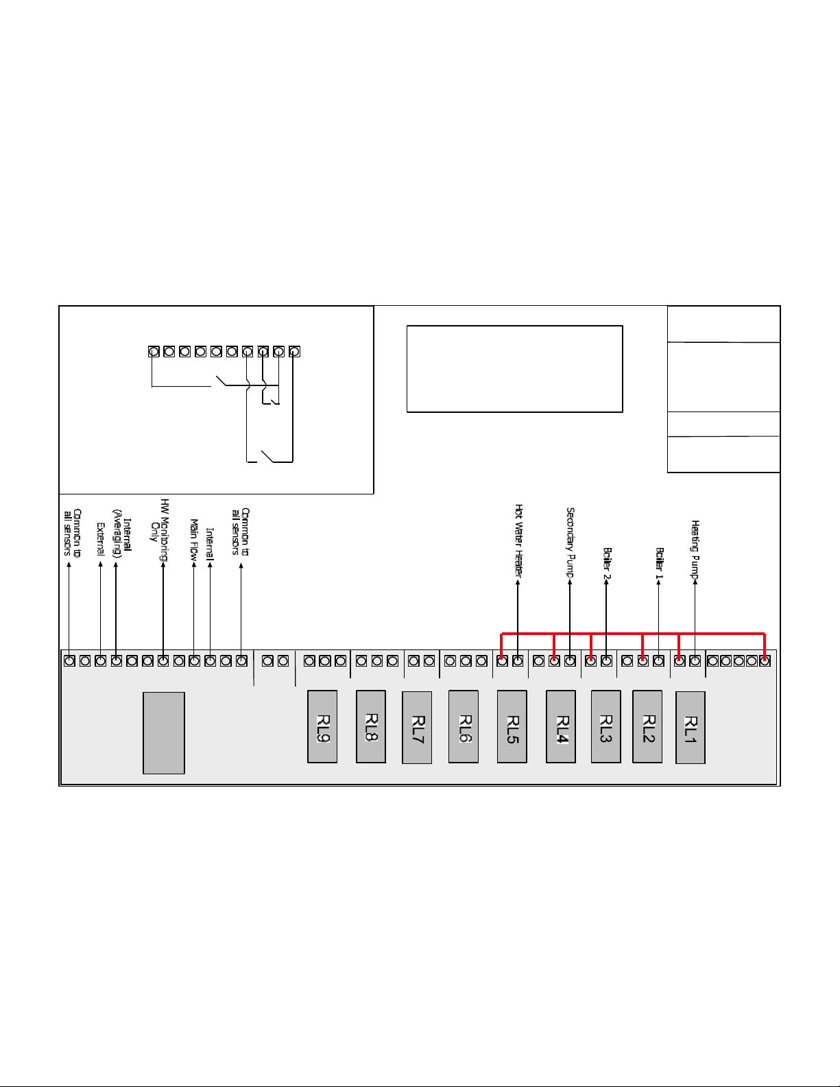
WIRING INSTRUCTIONS
RELAY BANK for Boiler Sequencer (Fixed or Variable) With Pump Overrun.
Relay 1 = Pump
Relay 2 = Boiler 1
Relay 3 = Boiler 2
Relay 4 = Boiler 3
Continue if more boilers are required ...
RELAY BANK configuration for Boiler Sequencer (Fixed or Variable) No Pump Overrun.
Relay 1 = Boiler 1
Relay 2 = Boiler 2
Relay 3 = Boiler 3
Relay 4 = Boiler 4
Continue if more boilers are required…..
RELAY BANK configuration for a Compensated zone.
Relay 1 = Pump
Relay 2 = Valve Open
Relay3 = Valve Closed
RELAY BANK configuration for an Optimised zone.
Relay 1 = Valve
RELAY BANK configuration for an Optimised zone with pump overrun.
Relay 1 = Pump
Relay 2 = Valve
RELAY BANK configuration for a HILO zone.
Relay 1 = Low fire
Relay2 = High fire
WHEN CONFIGURING ZONE TYPES FOR BOILER SYSTEMS, THIS IS THE ORDER THAT
SHOULD BE OBSERVED.
1.BOILER SEQUENCER
2.COMPENSATED ZONE
3.OPTIMISED ZONES
WHEN CONFIGURING ZONE TYPES FOR WARM AIR, THIS IS THE ORDER THAT
SHOULD BE OBSERVED.
1.HILO ZONES
2.OPTIMISED ZONES
Revision 2 18th August 2002 Page 30 of 38
Page 31
INPUTS
NoInputsarerequiredforthis
Bridging+and1-8enablestheabovefunction.
system.
+
2
1
3
5678 +
4
ImportantNote
Beldon8451cableMUSTbeusedwhen
wiringHeatmiserSensors.
RSPARTNUMBER:360-649
HEATMISER
PLUS
SystemTitle
3BoilerSequencer
with2compensated
zones.
HEATMISERUKLTD
DrawingNo:001
++
SensorInputs
345678
S
2
1
-
+
S
12vDC
NC
CNC
NO
RelayContacts-VoltFree
C
NOC
NOCNONCCNO
C
CNC
NO
C
NONCNO
E
E
N
NOC
NL
MAINS
Output
HeatmiserPlus
Page 32
INPUTS
e
r
NoInputsarerequiredforthis
Bridging+and1-8enablestheabovefunction.
system.
+
2
1
3
5678 +
4
ImportantNote
Beldon8451cableMUSTbeusedwhen
wiringHeatmiserSensors.
RSPARTNUMBER:360-649
HEATMISER
PLUS
SystemTitle
2BoilerSequencer
withpumpoverrun
1compensatedzon
and1Timedzonefo
Hotwater.
HEATMISERUKLTD
DrawingNo:002
++
SensorInputs
345678
S
2
1
-
+
S
12vDC
NC
CNC
NO
RelayContacts-VoltFree
C
NOC
NOCNONCCNO
C
CNC
NO
C
NONCNO
E
E
N
NOC
NL
MAINS
Output
HeatmiserPlus
Page 33
INPUTS
a
l
g
Heating
Timer
HotWater
Timer
+123
5678 +
4
Holiday
Switch
ImportantNote
Beldon8451cableMUSTbeusedwhen
wiringHeatmiserSensors.
RSPARTNUMBER:360-649
HEATMISER
PLUS
2Boilersequencerwithintern
controlvia2internalaveragin
sensors,withpumpoverrun.
Hotwatercontroltimedonly
withsecondarypumprunon
andhotwatertemperature
monitoring
HEATMISERUK
DrawingNo:003
++
SensorInputs
345678
S
2
1
-
+
S
12vDC
NC
CNC
NO
RelayContacts-VoltFree
C
NOC
NOCNONCCNO
C
CNC
NO
C
NONCNO
E
E
N
NOC
NL
MAINS
Output
HeatmiserPlus
Page 34
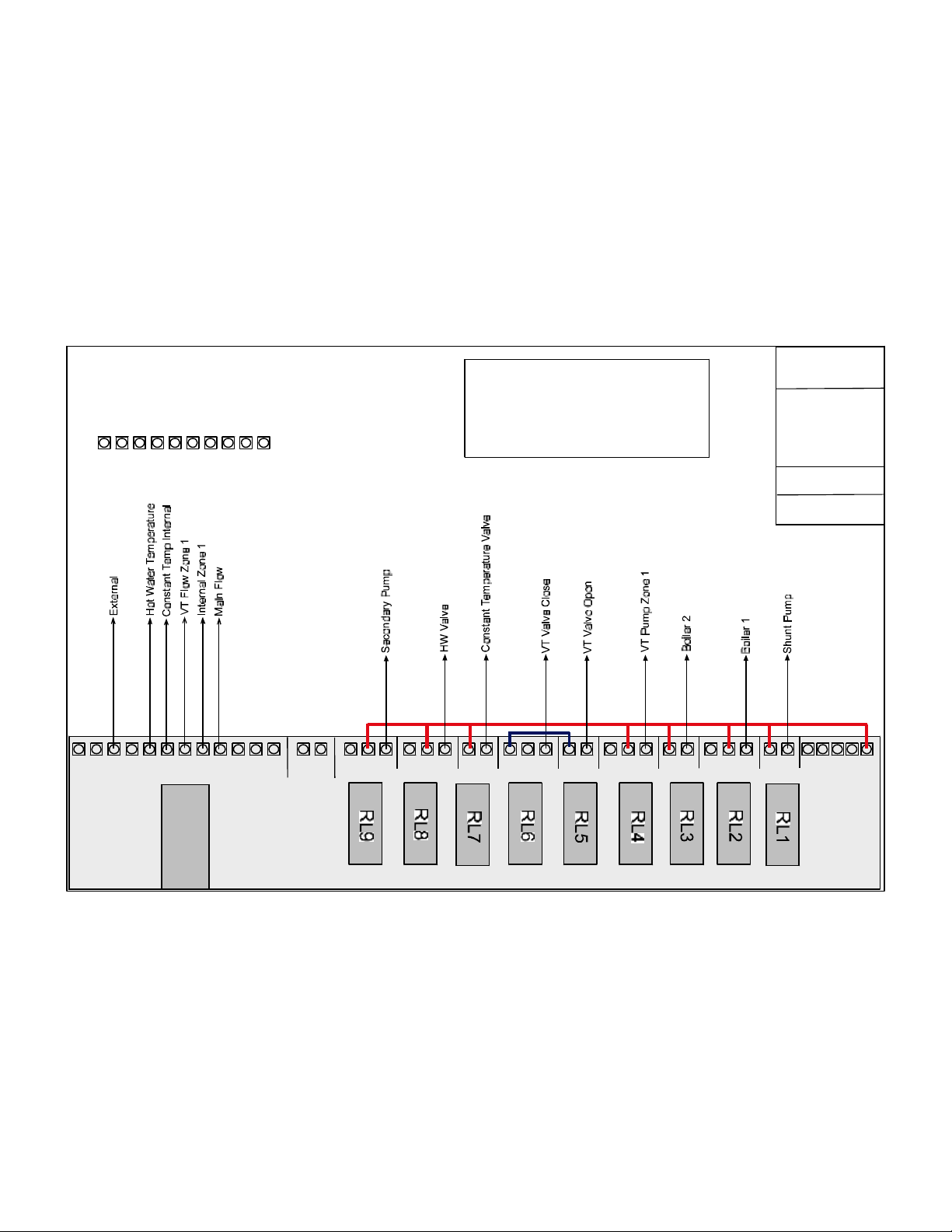
INPUTS
NoInputsarerequiredforthis
Bridging+and1-8enablestheabovefunction.
system.
+
2
1
3
5678 +
4
ImportantNote
Beldon8451cableMUSTbeusedwhen
wiringHeatmiserSensors.
RSPARTNUMBER:360-649
HEATMISER
PLUS
SystemTitle
2BoilerSequencerwith
pumpoverrun.1
compensatedzone,
1Constanttempheating
zone,1Hotwaterzone
and1secondarypump.
HEATMISERUKLTD
DrawingNo:004
++
SensorInputs
345678
S
2
1
-
+
S
12vDC
NC
CNC
NO
RelayContacts-VoltFree
C
NOC
NOCNONCCNO
C
CNC
NO
C
NONCNO
E
E
N
NOC
NL
MAINS
Output
HeatmiserPlus
Page 35
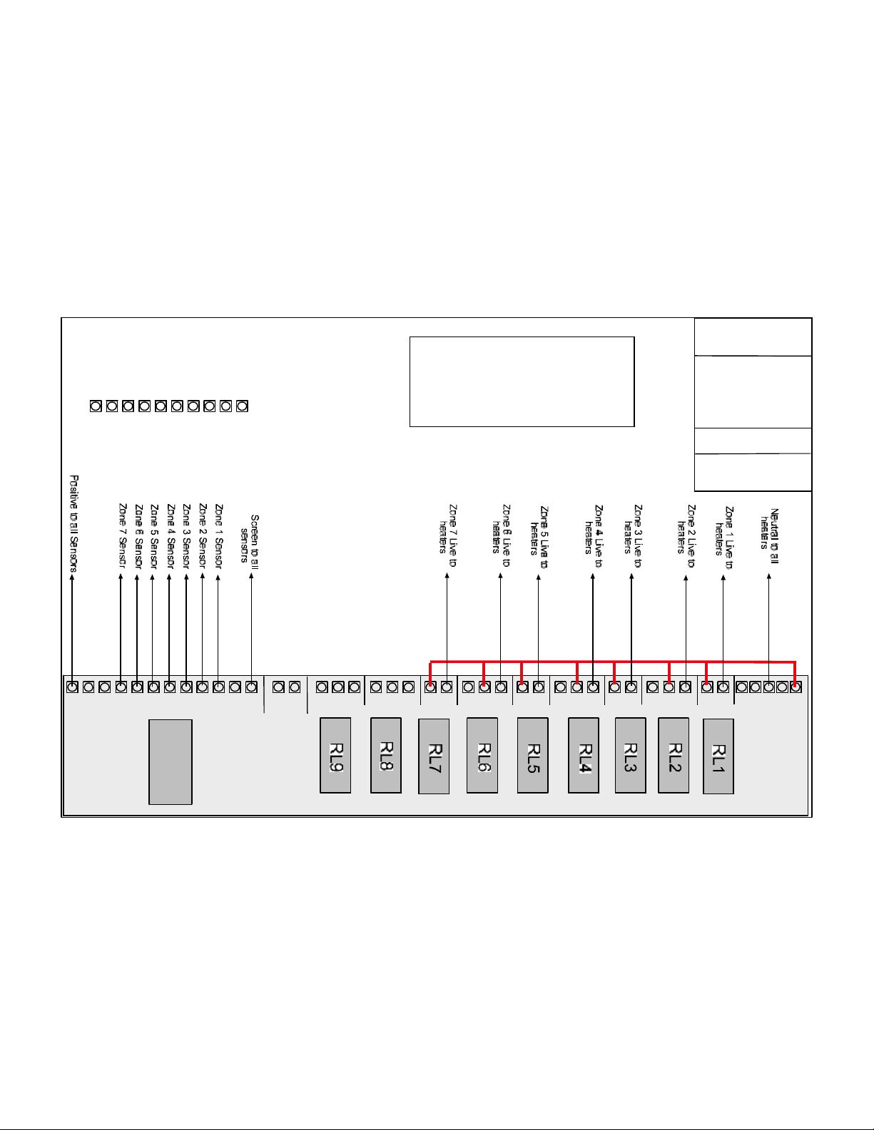
INPUTS
345678
HEATMISER
ImportantNote
Beldon8451cableMUSTbeusedwhen
+
2
+
1
wiringHeatmiserSensors.
RSPARTNUMBER:360-649
PLUS
7ZonesofRadiant
Tubes
HEATMISERUK
DrawingNo-005
++
SensorInputs
345678
S
2
1
-
+
S
12vDC
NC
CNC
NO
RelayContacts-VoltFree
C
NOC
NOCNONCCNO
C
CNC
NO
C
NONCNO
E
E
N
NOC
NL
MAINS
Output
HeatmiserPlus
Page 36
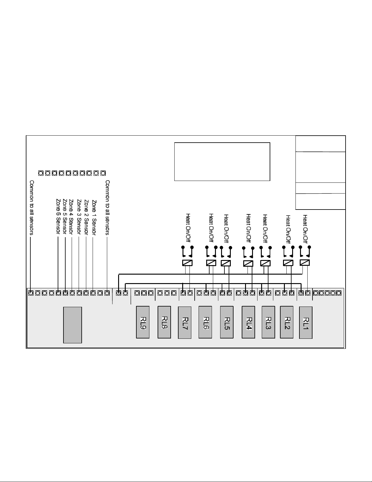
INPUTS
345678
HEATMISER
ImportantNote
Beldon8451cableMUSTbeusedwhen
wiringHeatmiserSensors.
+
2
+
1
RSPARTNUMBER:360-649
PLUS
7Zonesof
wamairheaters
HEATMISERUK
DrawingNo-006
++
SensorInputs
345678
S
2
1
-
+
S
12vDC
NC
CNC
NO
RelayContacts-VoltFree
C
NOC
NOCNONCCNO
C
CNC
NO
C
NONCNO
E
E
N
NOC
NL
MAINS
Output
HeatmiserPlus
Page 37
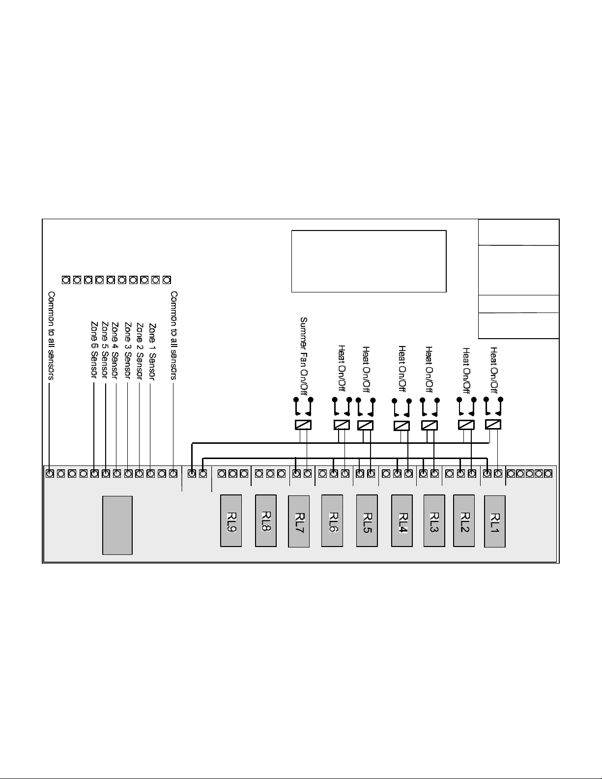
INPUTS
345678
HEATMISER
ImportantNote
Beldon8451cableMUSTbeusedwhen
wiringHeatmiserSensors.
+
2
+
1
RSPARTNUMBER:360-649
PLUS
6Zonesof
wamairheaters
and1Summer
fanzone
HEATMISERUK
DrawingNo-007
++
SensorInputs
345678
S
2
1
-
+
S
12vDC
NC
CNC
NO
RelayContacts-VoltFree
C
NOC
NOCNONCCNO
C
CNC
NO
C
NONCNO
E
E
N
NOC
NL
MAINS
Output
HeatmiserPlus
Page 38

Heatmiser Plus User Manual
HEATMISER SENSOR INFORMATION
Only Heatmiser sensors can be used with the Heatmiser controls.
There are 5 different types of sensors available each with a specific purpose.
Heatmiser Immersion.
The Heatmiser Immersion is used on boilers systems and is designed to measure flow
Temperatures. The Immersion sensor is supplied with a 8.4cm brass pocket for inserting into the
pipe-work.
Heatmiser Internal Sensors
Heatmiser Internal sensors should be fit about 5ft up and out of direct sunlight or other heat
sources.
Heatmiser External Sensors
Heatmiser External sensors should be fit on North Facing walls out of direct sunlight.
Heatmiser Clamp On Flow Sensors
Heatmiser Clamp on flow sensors should be used on cylinders and on systems which cannot be
drained down. Clamp on sensors should be fit 2/3 from the top of the cylinder or on
compensating circuits 3-4 ft away from the pump.
Heatmiser Radiant Sensors
Heatmiser Radiant sensors should be fit about 5ft up and out of direct sunlight or other heat
sources. They should be installed within the reflected area of the radiant tubes.
Cable required
You should use BELDON 8451 or equivalent. RS Part Number 360-649.
This cable is a twin, twisted screened cable.
Revision 2 18th August 2002 Page 38 of 38
Page 39
ر© ¬± ½´¿·³
Û²¸¿²½»¼
Û²¸¿²½» §±«® »²»®¹§ »ºº·½·»²½§
Ý¿°·¬¿´ ß´´±©¿²½»
ÛÝ ßK- © ¸»® » ²» © ³¿ ½¸· ²» ®§ ·-
·²- ¬¿´ ´»¼á
¬¸ » -« °°´ ·» ® ·- ¿ ¾´ » ¬± ·¼ »² ¬· º§ ¬ ¸»
·²ª »-¬ ³ »² ¬ ·² ¯ «¿´ ·º§ ·²¹ »¯« ·°³ »²¬
¿² ¼ © ¸»®» ¬¸ » » ²¼ ó«-» ® ¸ ¿- ·² ½« ®® »¼
½¿ °·¬ ¿´ » ¨° »² ¼·¬ «®» ±² ¬¸¿ ¬ »¯«·° ³»² ¬ò
Ï ×º × ¸¿ª» ¿ -»®ª ·½» ½±² ¬®¿½ ¬ô ½¿² × ½ ´¿·³
ß Ì ¸» »² ¼ó«- »® ½ ¿² ½ ´¿ ·³ ©¸ »®»
±® ½±®° ±®¿ ¬·±² ¬¿¨ô ¿°¿® ¬ º® ±³ ¬¸± -»
©¸ ± ¿ ®» ´ »¿ -·²¹ ¬ ¸» ¿ --»¬ - ·ò» ò ¬¸ »
»²¼ ó«- »®ô ²±¬ ¬¸» -«°°´ ·»® ±® ½±² ¬®¿½¬±®ò
ر ©»ª» ®ô ·² ª»- ¬³ »²¬- º ®±³ ïé ß°® ·´
Ï É¸± ½ ¿² ½ ´¿·³ á
Ú·® -¬ ½¸»½ µ ¬¸» Û²» ®¹§ Ì» ½¸ ²± ´±¹§ Ô ·-¬ ¾»º± ®» ·²ª»- ¬·²¹ ·² ¿ ²§ ² »© » ²»®¹§ -¿ª ·²¹
¬»½ ¸²±´± ¹§ ¬ ± »- ¬¿¾ ´·-¸ ¬¸ ¿¬ ·¬ ¯« ¿´ ·º·» - º±® ¿² ÛÝ ßò DZ« ½ ¿² º ·² ¼ ¬ ¸» ´· -¬ ¿¬
©© ©ò»½¿ ò¹±ªò« µ
DZ« ½¿² ½ ´¿·³ ¬¸ » ¿ ´´±© ¿²½ » ±² ¬¸» ½ ±-¬ ±º ¬¸» °®± ¼« ½¬ô ¿ ´±² ¹ © ·¬¸ ¿²§ ½ ±- ¬- ¼·® »½¬´§
¿-- ±½·¿¬ »¼ ©·¬¸ ¬ ¸» °®± ª·- ·±² ±º ¬¸ » °®± ¼«½¬ô -«½ ¸ ¿- ·² -¬¿ ´´¿¬·± ² ½± -¬- ò ׺ ¬ ¸» ¯ «¿ ´·º §·² ¹
»¯ «·° ³ »²¬ · - ·²½ ±® °± ®¿¬ »¼ ·²¬± ¿ ´¿ ®¹»® °· »½» ± º »¯ «·°³ »² ¬ô ¬¸ » ½´¿·³ ª ¿´«»- -¸ ±©² ¿¬
©© ©ò»½¿ ò¹±ªò« µ -¸± «´¼ ¾» « -»¼ ò
Ý´ ¿·³ §± «® ÛÝ ß ¿- ° ¿®¬ ± º §± «® ²± ®³ ¿´ ·² ½±³» ñ½±® °± ®¿¬ ·±² ¬¿¨ ® »¬« ®² ½ ¿´½ «´ ¿¬· ±² -
P - »» § ±« ® ¬¿¨ ®» ¬«®² º± ®³ ¿²¼ ¿½½ ±³° ¿²§ ·²¹ ²± ¬»-ò
ßò Þ« -·²» --»- ·² ¬¸ » ½¸¿ ®¹» ¬± ·²½ ±³ » ¬¿¨
îð ðî ·² ¯ «¿´ ·º§·² ¹ » ²»®¹ § - ¿ª·² ¹
·² ·²-¬¿ ´³ »² ¬-á
Ï É ¸¿¬ ·º × °¿§ º±® ¯« ¿´·º§ ·²¹ °®± ¼«½¬ -
»¯« ·°³» ²¬ º±® ´» ¿-· ²¹ô ´» ¬¬·² ¹ ±® ¸· ®»
½¿ ² ¯ «¿´·º § º±® ¿² ÛÝ ßò
´±½ ¿´ ¿« ¬¸±®· ¬·»-ô ½´¿·³ á
Ï Ý ¿² ° «¾´·½ ±®¹ ¿²· -¿¬ ·±²-ô º± ® »¨ ¿³ °´»
Û²¸¿²½» §±«® ½¿-¸ º´±©
¹»² »®¿´´ § § ±« ½ ¿² ½ ´¿· ³ ¬¸» ¿´´± ©¿² ½»-
¿- §±« ·²½«® ¬ ¸» »¨ °» ²¼·¬« ®»ò
ß Ì ¸» ² ±®³ ¿´ ¬ ¿¨ ®« ´»- ¿ °°´§ô ¾ «¬
¾» ½¿ «-» ¬ ¸» § ¼ ± ² ±¬ ° ¿§ ·²½± ³» ±®
½±® °±®¿ ¬·±² ¬¿¨ ô ¾ «¬ ¬ ¸» § ½ ¿² ³ ¿µ» «-»
±º ¬¸» Ô·-¬ ¬± °®±½ «®» »² »®¹ § -¿ª· ²¹ µ·¬ ò
ß Ò ±ô ° «¾´ ·½ ± ®¹¿ ²·- ¿¬·± ²- ½¿² ²±¬ ½´¿ ·³ ô
̸» -½¸»³» ·- ¾»·²¹ ¼»ª»´±°»¼ ¾§ ¬¸»
ײ´¿²¼ 못²«» ¿²¼ ̸» Ü»°¿®¬³»²¬
º±® Û²ª·®±²³»²¬ô Ú±±¼ ¿²¼ Ϋ®¿´
Яºº¿·®- шЬЫЪОЯч ¿²¼ ³¿²¿¹»¼ ¾§
¬¸» Ý¿®¾±² Ì®«-¬ò
̱ º·²¼ ±«¬ ³±®»ô ª·-·¬
©©©ò»½¿ò¹±ªò«µ ±® ½¿´´
ß½¬·±² Û²»®¹§ º®»» ±²
ðèðð ëè ëé çìò
ß½¬·±² Û²»®¹§ ·- ¿ Ý¿®¾±² Ì®«-¬ °®±¹®¿³³»ò ̸» Ý¿®¾±² Ì®«-¬ ·- ¿ ½±³°¿²§ ´·³·¬»¼ ¾§ ¹«¿®¿²¬»»ò
О»¹·-¬»®»¼ ·² Ы²¹´¿²¼ ¿²¼ Й¿´»- Т«³¾»® мпзронрт О»¹·-¬»®»¼ ¿¬ж з¬¸ Ъ´±±®ф н Э´»³»²¬K- Ч²²ф Ф±²¼±² ЙЭоЯ оЯЖ
w М¸» Э¿®¾±² М®«-¬ф оррот Я´´ О·¹¸¬- О»-»®ª»¼т
ɸ·´-¬ ©» ¸¿ª» ¬¿µ»² ®»¿-±²¿¾´» -¬»°- ¬± »²-«®» ¬¸¿¬ ¬¸» ·²º±®³¿¬·±² ½±²¬¿·²»¼ ©·¬¸·² ¬¸·- ´»¿º´»¬ ·- ½±®®»½¬ô ©» ¹·ª»
²± ©¿®®¿²¬§ ¿²¼ ³¿µ» ²± ®»°®»-»²¬¿¬·±² ¿- ¬± ·¬- ¿½½«®¿½§ ¿²¼ ©» ¿½½»°¬ ²± ´·¿¾·´·¬§ º±® ¿²§ »®®±®- ±® ±³·--·±²- ¿²¼
²±® ¼±»- ¬¸» Ý¿®¾±² Ì®«-¬ ²±® ¬¸» Ù±ª»®²³»²¬ò Ú±® ¬¿¨ ¿¼ª·½» §±« -¸±«´¼ ½±²-«´¬ §±«® ±©² ¬¿¨ ¿¼ª·-±®ò О»ºж ЪФппо
ЭЫЫрои ЫЭЯ ´»¿º´»¬ ¿с © йснпсро зжмз ЯУ Р¿¹» п
 Loading...