


HeatMaster
Installation, Operating and
Servicing Instructions
HM 60 N / 70 N / 100 N / 150 JUMBO
HM 60 N / 70 N / 100 N
With ACV BG 2000-S premix gas burner
HM 60 N / 70 N / 100 N
With ACV BM 101 oil burner
HM 150 JUMBO
With ACV BM 151 oil burner
excellence in hot water
66400501
INDEX |
|
INTRODUCTION |
1 |
Intended users of these instructions |
1 |
Symbols |
1 |
Applicable standards |
1 |
Warnings |
1 |
DESCRIPTION |
2 |
Operating principle |
2 |
Construction features |
2 |
TECHNICAL SPECIFICATION |
5 |
Maximum operating conditions |
5 |
Burner chamber plate |
5 |
Domestic hot water performances |
5 |
General features |
5 |
Dimensions |
6 |
INSTALLATION |
8 |
Boiler room |
8 |
Chimney connections |
8 |
Hot water connections |
10 |
Heating connection |
11 |
Oil supply connections |
11 |
Electrical connections |
12 |
Wiring diagram |
12 |
COMMISSIONING |
14 |
Filling the hot water and heating circuits |
14 |
BURNER FEATURES |
15 |
ACV BG 2000-S premix gas burners |
15 |
ACV BM 101 and BM 151 oil burners |
19 |
MAINTENANCE |
20 |
Service intervals |
20 |
Servicing the boiler |
20 |
Servicing the safety devices |
21 |
Servicing the burner |
21 |
Draining the boiler |
21 |
Spare parts |
21 |
USER GUIDE |
22 |
Using the boiler |
22 |
Boiler safety shutdown |
23 |
Resetting the oil burner |
23 |
Resetting the BG 2000-S premix burner |
23 |
Burner troubleshooting |
23 |
SERVICE RECORD |
24 |
INTRODUCTION
INTENDED USERS OF THESE INSTRUCTIONS
These instructions are intended for
-specifying engineers
-installing engineers
-end-users
-servicing engineers
SYMBOLS
The following symbols are used in these instructions:
Essential instruction for operating the system correctly.
Essential instruction for personal safety or environmental protection.
Danger of electrocution.
Risk of scalding.
APPLICABLE STANDARDS
The products have received the “CE” certificate in accordance with the standards prevailing in different countries (European Directives 92/42/EEC, “efficiency”, 90/396/EEC “gas appliances”). These products have also received the Belgian “HR+” (gas boilers) marks and “OPTIMAZ” (oil boilers) marks.
WARNINGS
These instructions are an integral part of the equipment to which they refer and must be supplied to the user.
The product must be installed and serviced by qualified engineers, in compliance with the prevailing standards.
ACV accepts no liability for any damage resulting from incorrect installation or from the use of components or fittings not specified by ACV.
Failure to observe instructions regarding tests and test procedures can result in personal injury or pollution risks.
Note:
ACV reserves the right to modify the technical specifications and components of its products without prior notice.
1

DESCRIPTION
OPERATING PRINCIPLE
The HeatMaster is a high performance, direct fired hot water storage heater, which has indirect heat transfer due to its Tank-in-Tank construction.
At the heart of the HeatMaster is a stainless steel cylinder through which the flue tubes pass. This is surrounded by a mild steel shell containing the primary water (neutral fluid). The outer shell extends down to the combustion chamber and even around the flue tubes. The area of the heat transfer surface is therefore much greater than that of standard direct fired water heaters.
A circulating pump fitted to the primary circuit moves the water around the tank, heating it faster and maintaining an even temperature across the primary jacket.
The burner, either gas or oil, fires onto the primary water which indirectly heats the stainless steel cylinder containing the DHW. As with all Tank-in-Tanks, this is corrugated over its full height and suspended in the HeatMaster by its hot and cold water connections.
The cylinder expands and contracts during use and this, together with the fact that cold water does not come into contact with the intense heat of the burner flame, means that limescale buildup is prevented.
This scale resistant feature, along with the corrosion resistance of stainless steel, eliminates the need for sacrifical anodes.
The HeatMaster has one very major advantage over other direct fired water heaters - because it heats the DHW with a primary circuit, this primary water can be used to provide central heating as well.
By connecting two, three, four or more HeatMasters together in a module, most hot water and heating demands can be met.
Indeed, when used in conjunction with HR and Jumbo hot water storage tanks the Heatmaster can supply even the largest hot water requirement.
Standard equipment
The HeatMaster 60 N / 70 N / 100 N and 150 Jumbo has the following items as standard :
-On/off switch
-Summer/Winter switch
-Timeclock
-primary circulating shunt pump
-primary expansion vessels
-primary safety valve
-pressure and temperature gauge
-drain valve
-body completely insulated in rigid polyurethane foam
CONSTRUCTION FEATURES
Outer body
The outer body containing the primary fluid is made of thick STW 22 steel.
TANK-IN-TANK heat exchanger
The ring-shaped inner tank with its large heating surface for producing domestic hot water is built of Chrome/Nickel 18/10 stainless steel. It is corrugated over its full height by an exclusive production process and entirely argon arc welded by the TIG (Tungsten Inert Gas) method.
Combustion gas circuit
The combustion gas circuit is paint-protected and comprises:
• Flue pipes
Depending on output, HeatMaster models contain several steel flue pipes with an internal diameter of 64 mm. Each pipe is fitted with a baffle of special steel designed to improve heat exchange and reduce flue gas temperature.
• Combustion chamber
The combustion chamber on HeatMaster models is entirely water cooled.
Insulation
The boiler body is fully insulated by rigid polyurethane foam with a high thermal insulation coefficient, sprayed on without the use of CFCs.
Casing
The boiler is covered by a steel jacket which has been scoured and phosphated before being stove enamelled at 220 °C.
The jacket of the HM 150 Jumbo is delivered separately and must be assembled on site following the instructions supplied with it.
Burner
All HeatMaster models can be fitted with pressure jet gas burners or oil burners. The HeatMaster 60, 70 and 100 can also be fitted with the low-NOx pre-mix BG 2000 gas burner.
2

DESCRIPTION
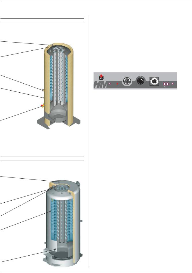
Features of HeatMaster 70 N / 100 N
Top cover
Automatic air vent
Domestic cold water inlet
Heating circuit filling valve with removable hose and non-return valve
Primary expansion vessel
Primary shunt pump
Casing front panel
Primary circuit
Burner chamber plate
Flue reduction collar
Central heating flow pipe
Domestic hot water outlet
Flue pipes and turbulators
Tank-in-Tank heat exchanger
Insulation
Burner
Heating return
Combustion chamber
Safety features of the HeatMaster 60 N |
Control panel HeatMaster 60 N |
|||
Thermal reset high |
|
|
|
|
limit thermostat |
|
|
|
|
|
Combined temperature |
|
Manual reset high |
|
|
|
|||
Manual reset high |
and pressure gauge |
|
limit thermostat |
|
|
|
|
|
|
limit thermostat |
|
|
|
|
|
Burner |
|
|
|
|
lockout |
|
Time clock |
|
Low water |
indicator |
|
|
|
|
|
|
|
|
pressure switch |
|
|
|
|
|
|
|
|
|
|
|
|
|
|
Primary safety valve |
|
|
|
|
|
|
|
|
|
|
|
|
|
|
|
|
|
|
|
|
|
|
|
|
|
|
|
|
|
|
|
Primary circuit low |
|
|
|
|
|
|
|
water pressure |
|
|
|
|
|
|
|
indicator |
|
Control |
ON / OFF |
|
|
|
|
|
|
|
|||||
Control thermostat |
thermostat |
switch |
|
||||
|
|
|
|
|
|
||
High limit cutoff |
|
|
|
|
|
|
|
indicator |
|
Summer / Winter switch |
|||||
3
DESCRIPTION
Safety features of the HeatMaster 70 N and 100 N
Thermal reset high limit thermostat
Manual reset high limit thermostat
Low water pressure switch
Control thermostat
Primary safety valve
Safety features of the HeatMaster 150 Jumbo
Primary safety valve
Thermal reset high limit thermostat
Manual reset high limit thermostat
Low water pressure switch
Control thermostat
Control panel HeatMaster 70 N and HeatMaster 100 N
Combined temperature |
Manual reset high |
and pressure gauge |
limit thermostat |
Burner
lockout Summer / Winter switch indicator
Time clock |
Primary circuit low water pressure indicator
Control |
ON / OFF |
thermostat |
switch |
High limit cutoff indicator
Control panel HeatMaster 150 Jumbo
|
|
|
Mains power |
|
|
|
electrical connection |
|
|
|
(multi-pin plug) |
Combined temperature |
|
|
|
and pressure gauge |
|
|
Primary circuit low |
|
|
|
|
|
|
bar |
water pressure indicator |
Relay base |
.. .... |
|
|
|
. . |
|
|
|
.. |
|
|
|
. . |
|
|
|
. . |
|
|
|
. |
. |
|
|
|
. . |
|
Time clock |
|
|
|
|
|
|
ON / OFF switch |
Fuse |
|
|
Manual reset high |
|
|
|
|
|
|
|
limit thermostat |
Control thermostat |
|
|
|
|
|
|
Thermal reset high |
|
|
|
limit thermostat |
Servicing socket |
|
|
|
(230 V ˜ 50 Hz) |
|
|
|
4

MAXIMUM OPERATING CONDITIONS
Maximum service pressure (tank full of water)
-Primary circuit: 3 bar
-Secondary circuit: 10 bar
Test pressure (tank full of water)
-Primary circuit: 4.5 bar
-Secondary circuit: 13 bar
Operating temperature
- Maximum temperature: 90 °C
Water quality
•Chlorures: < 150 mg/l (304)
<2000 mg/l (Duplex)
•6 ≤ ph ≥ 8
TECHNICAL SPECIFICATION
BURNER CHAMBER PLATE
The burner chamber plate has 4 threads (M 10 x 20) for attaching the burner. It is protected from heat by a blanket insulation.
5xØ6.5(M8) |
Ø28 |
|||||
Ø130 |
||||||
60 |
|
|
|
|
|
|
60 |
|
|
|
|
|
|
|
|
|
|
|
|
|
|
|
|
|
|
|
|
|
|
|
|
|
|
|
|
60 |
|
60 |
|
||
DOMESTIC HOT WATER PERFORMANCES
|
|
HM 60 N |
HM 60 N |
HM 70 N |
HM 70 N |
HM 100 N |
HM 100 N |
HM 150 |
|
|
BM 101 |
BG 2000-S/60 |
BM 101 |
BG 2000-S/70 |
BM 101 |
BG 2000-S/100 |
JUMBO |
Peak delivery at 40 °C |
L/10’ |
474 |
474 |
646 |
646 |
905 |
905 |
1504 |
Peak delivery at 45 °C |
L/10’ |
378 |
378 |
543 |
543 |
777 |
777 |
1289 |
Peak delivery at 60 °C |
L/10’ |
245 |
245 |
346 |
346 |
514 |
514 |
870 |
Peak delivery at 70 °C |
L/10’ |
193 |
193 |
268 |
268 |
343 |
343 |
700 |
Peak delivery at 80 °C |
L/10’ |
135 |
135 |
207 |
207 |
258 |
258 |
540 |
|
|
|
|
|
|
|
|
|
Peak delivery at 40 °C |
L/60’ |
1942 |
1942 |
2133 |
2133 |
3172 |
3172 |
4828 |
Peak delivery at 45 °C |
L/60’ |
1656 |
1656 |
1794 |
1794 |
2680 |
2680 |
4138 |
Peak delivery at 60 °C |
L/60’ |
1106 |
1106 |
1219 |
1219 |
1813 |
1813 |
2864 |
Peak delivery at 70 °C |
L/60’ |
681 |
681 |
971 |
971 |
1226 |
1226 |
2131 |
Peak delivery at 80 °C |
L/60’ |
499 |
499 |
636 |
636 |
893 |
893 |
1362 |
|
|
|
|
|
|
|
|
|
Continuous delivery at 40 °C |
L/h |
1835 |
1835 |
1835 |
1835 |
2776 |
2776 |
3989 |
Continuous delivery at 45 °C |
L/h |
1573 |
1573 |
1573 |
1573 |
2379 |
2379 |
3419 |
Continuous delivery at 60 °C |
L/h |
1101 |
1101 |
1067 |
1067 |
1665 |
1665 |
2393 |
Continuous delivery at 70 °C |
L/h |
791 |
791 |
918 |
918 |
1104 |
1104 |
1718 |
Continuous delivery at 80 °C |
L/h |
455 |
455 |
580 |
580 |
804 |
804 |
987 |
|
|
|
|
|
|
|
|
|
Reheat time at 60 °C |
min |
9 |
9 |
16 |
16 |
13 |
13 |
17 |
|
|
|
|
|
|
|
|
|
GENERAL FEATURES
|
|
HM 60 N |
HM 70 N |
HM 100 N |
HM 150 |
|
|
|
|
|
JUMBO |
Maximum Input |
kW |
69.9 |
69.9 |
107.0 |
154.0 |
Maximum Output |
kW |
62.5 |
63.0 |
96.8 |
139.1 |
Maintenance loss at 60 °C as rated value |
% |
0.57 |
0.60 |
0.65 |
0.52 |
Total capacity |
L |
162 |
239 |
330 |
645 |
Primary circuit capacity |
L |
82 |
108 |
130 |
245 |
Heating connection |
Ø |
11/2” |
11/2” |
11/2” |
DN 50 |
Hot water connection |
Ø |
3/4” |
1” |
1” |
2” |
Hot water tank heat exchange surface |
m2 |
2.46 |
3.14 |
3.95 |
5.30 |
Weight empty |
Kg |
220 |
270 |
320 |
530 |
Pressure drop primary circuit |
mbar |
54 |
46 |
83 |
120 |
|
|
|
|
|
|
5
TECHNICAL SPECIFICATION
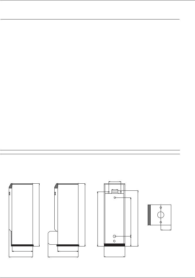
DIMENSIONS
The units are delivered fully assembled, tested and packed on a timber base with shockproof edges and protected by heat-shrunk plastic film. On reception and after unpacking, check the equipment for damage. For transport purposes, refer to the weight (page 5) and dimensions given below.
|
A mm |
B mm |
C mm |
D mm |
E mm |
F mm |
G Ø mm |
H mm |
J mm |
K mm |
|
|
|
|
|
|
|
|
|
|
|
HM 60 N |
1698 |
1583 |
538 |
625 |
540 |
390 |
150 |
1098 |
281 |
1665 |
|
|
|
|
|
|
|
|
|
|
|
HM 60 N BG 2000-S 60 |
1698 |
1583 |
538 |
801 |
540 |
390 |
150 |
1098 |
281 |
1665 |
|
|
|
|
|
|
|
|
|
|
|
HM 70 |
1743 |
1630 |
678 |
797 |
680 |
390 |
150 |
1289 |
285 |
1720 |
|
|
|
|
|
|
|
|
|
|
|
HM 70 N BG 2000-S 70 |
1743 |
1630 |
680 |
937 |
680 |
390 |
150 |
1289 |
285 |
1720 |
|
|
|
|
|
|
|
|
|
|
|
HM 100 N |
2093 |
2030 |
680 |
797 |
680 |
390 |
150 |
1693 |
285 |
2120 |
|
|
|
|
|
|
|
|
|
|
|
HM 100 N BG 2000-S 100 |
2093 |
2030 |
680 |
937 |
680 |
390 |
150 |
1693 |
285 |
2120 |
|
|
|
|
|
|
|
|
|
|
|
HM 150 Jumbo |
2124 |
2117 |
1020 |
1440 |
1020 |
600 |
250 |
1383 |
590 |
2250 |
|
|
|
|
|
|
|
|
|
|
|
HeatMaster 60 N
Without burner |
With ACV BG 2000-S |
|
premix gas burner |
F
G
A |
A |
B |
H K |
C/2
J
C |
|
C |
D |
D |
E |
6
TECHNICAL SPECIFICATION
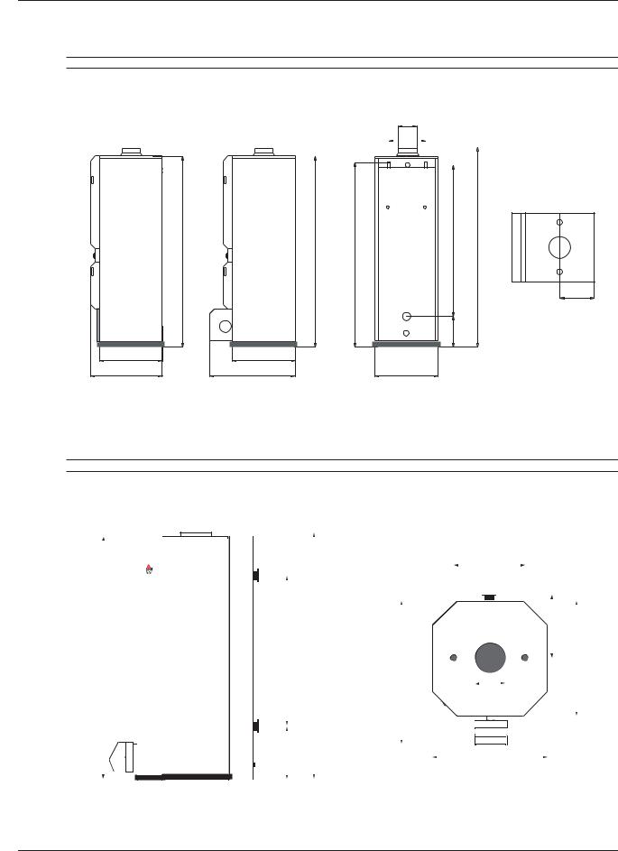
HeatMaster 70 N and HeatMaster 100 N
Without burner |
With ACV BG 2000-S |
G |
|
|
|
|||||
|
premix gas burner |
F |
|
|
|
|||||
|
|
|
|
|
|
|
|
|||
|
|
|
|
|
|
|
|
|
|
|
|
|
|
|
|
|
|
|
|
|
|
|
|
|
|
|
|
|
|
|
|
|
|
|
|
|
|
|
|
|
|
|
|
K
A |
A |
B |
H |
C/2
J
C |
|
C |
D |
D |
E |
HeatMaster 150 Jumbo
F
562
A |
H |
|
K |
C |
D
G
J
E
7
INSTALLATION
BOILER ROOM
Important
•Keep vents free at all times.
•Do not store inflammable products in the boiler room.
•Do not store corrosive products near the boiler, such as paints, solvents, chlorine, salt, soap and other cleaning products.
•If you smell gas, do not switch on the light or light a flame. Turn off the mains gas tap at the meter and inform the appropriate services immediately.
Access
The boiler room must be large enough to allow good access to the boiler. The following minimum distances are required around the boiler:
- front |
500 mm |
- side |
100 mm |
- behind |
150 mm |
- above |
700 mm |
Ventilation
The boiler room must be fitted with top and bottom vents sized according to the table below or to current regulations.
The table below gives an example conforming to the Belgian standards.
Ventilation |
|
60 N |
70 N |
100 N |
150 |
|
|
|
|
|
|
Jumbo |
|
Min. fresh air |
|
|
|
|
|
|
requirement |
m3/h |
126 |
126 |
194 |
278 |
|
Bottom |
dm2 |
2.11 |
2.11 |
3.20 |
4.8 |
|
Top |
dm2 |
2.0 |
2.0 |
2.0 |
2.0 |
|
|
||||||
|
|
|
|
|
|
|
Other countries should refer to their own standards.
Base
The base on which the boiler rests must be made of non-combustible materials.
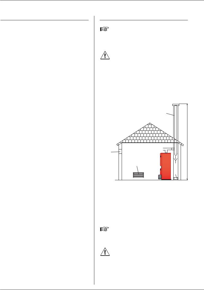
CHIMNEY CONNECTIONS
IMPORTANT
Boilers must be installed by an approved heating engineer, in accordance with the prevailing local standards and regulations.
Flue size should not be less then the outlet size of the boiler.
Chimney connection type: B23
The boiler is connected to the chimney by a metal pipe rising at an angle from the boiler to the chimney.
A flue disconnection piece is required.
This must be easy to remove to give access to the flue pipes when servicing the boiler.
A.Top vent
B.Bottom vent
C.Draught regulator
D.Inspection window
E.Height of lined chimney
F.Chimney diameter
A
B
F
E
C
D
Chimney |
60 N |
70 N |
100 N |
150 |
minimum flue diameter |
|
|
|
Jumbo |
|
|
|
|
|
E = 5 m Ø F min. mm |
189 |
189 |
234 |
286 |
E = 10 m Ø F min. mm |
159 |
159 |
178 |
250 |
E = 15 m Ø F min. mm |
150 |
150 |
150 |
250 |
|
|
|
|
|
Note:
Regulations vary from country to country therefore the table above is intended only as a guide.
Due to the high efficiency of our boilers, the flue gasses exit at low temperature. Accordingly, there is risk that the flue gasses could condense, which could damage the chimney. In order to avoid this risk, it is strongly recommended that the chimney be lined.
8
 Loading...