


HeatMaster®
Installation, Operating and
Servicing Instructions
HeatMaster® 201
excellence in hot water
28/09/2005 - 66402500.B

INDEX |
|
INTRODUCTION |
1 |
Target group |
1 |
Symbols |
1 |
Certification |
1 |
General information and safety instructions |
2 |
USER GUIDE |
2 |
Using the boiler |
2 |
Setting the parameters |
3 |
DESCRIPTION |
4 |
Operating principle |
4 |
Packing |
4 |
Construction features |
4 |
TECHNICAL SPECIFICATION |
6 |
Effective dimensions |
6 |
General characteristics |
6 |
Maximum operating conditions |
7 |
Domestic hot water performances |
7 |
HeatMaster® setting instructions |
7 |
INSTALLATION |
8 |
Boiler room |
8 |
Chimney connections |
8 |
Hot water connections |
9 |
Heating connection |
10 |
Electrical connections |
10 |
COMMISSIONING |
12 |
Filling the hot water and heating circuits |
12 |
BURNER FEATURES |
12 |
ACV BG 2000-M modulating premix gas burner |
12 |
MAINTENANCE |
14 |
Service intervals |
14 |
Servicing the boiler |
14 |
Servicing the safety devices |
14 |
Servicing the burner |
14 |
Draining the boiler |
14 |
MCBA FOR SPECIALISTS: INSTALLER, |
|
SERVICE ENGINEER |
15 |
Pilot mode |
15 |
Safety stop (Error mode) |
16 |
Setting the parameters |
17 |
Entering the code |
20 |
Information on the installation |
20 |
Communication mode (with code) |
21 |
Error mode |
21 |
SPARE PARTS |
22 |
Jackets |
22 |
Accessories |
22 |
Setting and electrical accessories |
22 |
Burner |
22 |
SERVICE RECORD |
23 |
Installation details |
23 |
Service notes |
23 |
INTRODUCTION
TARGET GROUP
This manual is intended for the use of:
-final users of the appliance;
-the engineer installing and starting up the appliance;
-the engineering and design department;
-the installer responsible for servicing or maintaining the appliance.
SYMBOLS
The following symbols are used in these instructions:
Essential instruction for operating the system correctly.
Essential instruction for personal safety or environmental protection.
Danger of electrocution.
Risk of scalding.
CERTIFICATION
The appliances carry the “CE” mark, in accordance with the standards in force in the various countries (European Directives 92/42/CEE “Efficiency” and 90/396/CEE “Gas Appliances”). They also carry the labels, “HR+”.
1
INTRODUCTION
GENERAL INFORMATION AND
SAFETY INSTRUCTIONS
IF YOU SMELL GAS:
-Immediately shut off the gas supply.
-Ventilate the boiler room.
-Do not use electrical appliances and do not switch anything on or off.
-Immediately notify your gas company and/or your installer.
General information
This documentation forms part of the items delivered with the appliance and must be given to the user to keep in a safe place!
This appliance must be serviced and repaired by an approved installer, in accordance with current standards in force.
ACV declines all liability for any damage caused as a result of incorrect installation or as a result of the use of components or connections that are not approved by ACV for this application.
Temperatures
This boiler is designed for central heating systems with a maximum outlet temperature of 90°C. Therefore, the central heating pipelines and the radiators must reach this temperature.
The waste-gas pipe lines must reach temperatures in excess of 100°C.
The hot water can reach temperatures in excess of 60°C.
Installation
Before installing and commissioning the boiler, first carefully read this manual.
Position the HeatMaster® according to the safety rules and standards in force. You must comply with the ventilation requirements for the room where appliances of this type are installed. All air vents must remain unobstructed at all times.
It is prohibited to modify the interior of the appliance in any way, without the manufacturer’s prior written agreement.
Service
In order to ensure the appliance operates safely and correctly, it is important to have it serviced and reconditioned every year by an installer or an approved service company.
Faults
Despite the strict quality standards imposed on its appliances by ACV during production, inspection, and transport, faults may occur.
Please immediately inform your approved installer about such faults.
Remember to give the fault code as it appears on the screen. (See also the list of faults on page 16)
Only genuine factory parts may be used as replacement parts.
Please go to page 22 for a list of spare parts and their ACV reference numbers.
Note: ACV reserves the right to change the technical characteristics and specification of its products without notices.
USING THE BOILER
Starting the burner
During operation, the burner starts automatically as soon as the temperature of the boiler is below the set point and goes off when this value is reached.
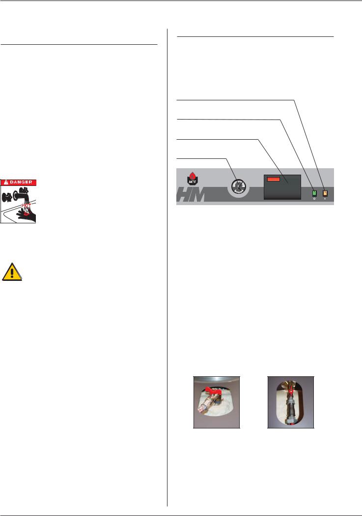
Control panel
Summer/Winter switch
Main switch
Display – MCBA controller
Thermostat-pressure gauge
The user must not attempt to gain access to the components inside the control panel.
Heating system pressure
From time to time you may need to top up the heating
system pressure. This pressure is indicated by the combined temperature and pressure gauge on the boiler control panel.
The minimum pressure when the boiler is cold should be 1 bar. The precise operating pressure required depends on the height of the building, and your installer will have informed you of this value at the time of installation (see Commissioning Section - Filling the hot water and heating circuits).
If the pressure falls below 1 bar, the boiler water pressure switch will turn the boiler off until pressure is restored.
To re-pressurise, the system needs to be topped up with water.
First, switch the boiler OFF on the on/off switch and isolate the external electrical supply. The fill valves A and B are located at the rear of the HeatMaster® (see photo A and B below). Open both valves and allow thesystem to fill. When the combined temperature and pressure gauge shows the required pressure, close both valves.
Replace the casing top front panel. Restore the power supply and switch the boiler on.
A B
Safety Valves
If water discharges from any of the safety valves, switch the boiler off and call a service engineer.
2
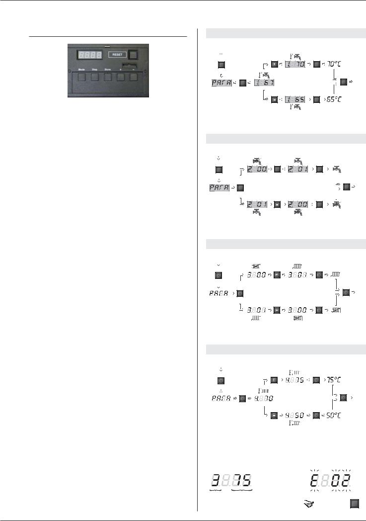
SETTING THE PARAMETERS
Setting the temperature of the hot water:
(Temperature of the hot water)
-Press “Mode”: “PARA” comes up on the screen.
-Press “Step”: the first digit is 1 and the last two digits indicate the current temperature setting for the hot water.
-To change this temperature, press the “+” or “-” keys until the temperature indicated by the last two digits is the desired temperature.
-Press “Store” to save the setting.
-Press “Mode” twice to return to Standby mode (normal operating mode).
Enabling and disabling hot water mode:
(hot water)
-Press “Mode”: “PARA” comes up on the screen.
-Press “Step” twice: the first digit is 2 and the last two digits
indicate the current setting:
00 = disabled;01 = enabled.
-To change this parameter, press the “+” or “-” keys until you reach the desired value:
00 = disabled;01 = enabled.
-Press “Store” to save the setting.
-Press “Mode” twice to return to Standby mode (normal operating mode).
Enabling and disabling central heating mode:
(heating)
-Press “Mode”: “PARA” comes up on the screen.
-Press “Step” three times: the first digit is 3 and the last two digits
indicate the current setting:
00 = disabled;01 = enabled.
- To change this parameter, press the “+” or “-” keys until you reach the desired value:
00 = disabled;01 = enabled.
-Press “Store” to save the setting.
-Press “Mode” twice to return to Standby mode (normal operating mode).
Setting the temperature of the central heating:
(the maximum temperature for the heating circuit)
-Press “Mode”: “PARA” comes up on the screen.
-Press “Step” four times: the first digit is 4 and the last two digits indicate the current temperature setting for the central heating.
-To change this temperature, press the “+” or “-” keys until the temperature indicated by the last two digits is the desired temperature.
-Press “Store” to save the setting.
-Press “Mode” twice to return to Standby mode (normal operating mode).
Fault:
The temperature setting of the appliance and the safety functions of its parts are constantly monitored by a microprocessor controller (MCBA).
In the event of a fault, this MCBA disables the appliance and displays an error code: the screen flashes and the first character is an “E” followed by the fault code, (see the list of faults on page 16).
Reset the appliance:
-Press “Reset” on the screen.
-If the fault code appears again, contact your installer.
|
USER GUIDE |
|
Setting the temperature of the hot water |
|
|
Stand by mode |
|
|
1 X |
1 X |
|
Mode |
Store |
|
1 X |
2 X Stand |
|
|
|
by |
Step |
Mode |
mode |
|
||
|
1 X |
|
Store
Enabling and disabling hot water mode
Stand by mode |
|
|
1 X |
1 X |
|
Mode |
Store |
|
2 X |
2 X Stand |
|
|
|
by |
Step |
Mode |
mode |
|
||
|
1 X |
|
Store
Enabling and disabling central heating mode
Stand by mode |
|
|
|
|
|
|
|
|
|
|
|
|
||||||||||||
|
|
1 X |
|
|
|
|
|
|
1 X |
|
||||||||||||||
|
|
|
|
|
|
|
|
|
|
|
|
|
|
|
|
|
|
|
|
|
|
|
|
|
|
|
|
|
|
|
|
|
|
|
|
|
|
|
|
|
|
|
|
|
|
|
|
|
|
|
|
Mode |
|
|
|
|
|
|
Store |
|
||||||||||||||
|
|
|
|
|
3 X |
|
|
|
|
|
|
|
|
|
2 X |
Stand |
||||||||
|
|
|
|
|
|
|
|
|
|
|
|
|
|
|
|
|
|
|
|
|
|
|
|
by |
|
|
|
|
|
|
|
|
|
|
|
|
|
|
|
|
|
|
|
|
|
Mode |
mode |
||
|
|
|
|
|
Step |
|
|
|
|
|
|
|
|
|
||||||||||
|
|
|
|
|
|
|
|
|
|
|
|
|
|
|
|
|
|
|
1 X |
|
||||
|
|
|
|
|
|
|
|
|
|
|
|
|
|
|
|
|
|
|
|
|
|
|
|
|
|
|
|
|
|
|
|
|
|
|
|
|
|
|
|
|
|
|
|
|
|
|
|
|
|
Store
Setting the temperature of the central heating
Stand by mode |
|
|
|
|
|
|
|
|
|
|
|
|
|||||||||||
|
|
1 X |
|
|
|
|
|
|
1 X |
|
|||||||||||||
|
|
|
|
|
|
|
|
|
|
|
|
|
|
|
|
|
|
|
|
|
|
|
|
|
|
|
|
|
|
|
|
|
|
|
|
|
|
|
|
|
|
|
|
|
|
|
|
|
|
Mode |
|
|
|
|
|
|
Store |
|
|||||||||||||
|
|
|
|
|
4 X |
|
|
|
|
|
|
|
|
2 X |
Stand |
||||||||
|
|
|
|
|
|
|
|
|
|
|
|
|
|
|
|
|
|
|
|
|
|
|
by |
|
|
|
|
|
|
|
|
|
|
|
|
|
|
|
|
|
|
|
|
Mode |
mode |
||
|
|
|
|
|
Step |
|
|
|
|
|
|
|
|
|
|||||||||
|
|
|
|
|
|
|
|
|
|
|
|
|
|
|
|
|
|
1 X |
|
||||
|
|
|
|
|
|
|
|
|
|
|
|
|
|
|
|
|
|
|
|
|
|
|
|
|
|
|
|
|
|
|
|
|
|
|
|
|
|
|
|
|
|
|
|
|
|
|
|
Store
|
|
Fault |
|
|
Reset the appliance |
|||||||
|
|
|
|
|
|
|
|
|
|
|
|
|
|
|
|
|
|
|
|
|
|
|
|
|
|
Status T°
1  Reset
Reset
3

DESCRIPTION
OPERATING PRINCIPLE
The HeatMaster® is a high performance, direct fired hot water storage heater, which has indirect heat transfer due to its Tank-in-
Tank construction.
At the heart of the HeatMaster® is a stainless steel cylinder through which the flue tubes pass. This is surrounded by a mild steel shell containing the primary water (neutral fluid). The outer shell extends down to the combustion chamber and even around the flue tubes.
The area of the heat transfer surface is therefore much greater than that of standard direct fired water heaters.
A circulating pump fitted to the primary circuit moves the water around the tank, heating it faster and maintaining an even temperature across the primary jacket.
The burner heats the primary water, which indirectly heats the stainless steel tank containing the hot water. As in all Tank-in-Tank systems, the tank is corrugated over its full height and suspended in the HeatMaster® by its hotand cold water connections.
The cylinder expands and contracts during use and this, together with the fact that cold water does not come into contact with the intense heat of the burner flame, means that limescale buildup is prevented.
This scale resistant feature, along with the corrosion resistance of stainless steel, eliminates the need for sacrifical anodes.
The HeatMaster® has one very major advantage over other direct fired water heaters - because it heats the DHW with a primary circuit, this primary water can be used to provide central heating as well.
By connecting two, three, four or more HeatMaster® together in a module, most hot water and heating demands can be met.
Indeed, when used in conjunction with HR and Jumbo hot water storage tanks the HeatMaster® can supply even the largest hot water requirement.
Standard equipment
The HeatMaster® 201 includes the following parts as standard:
-On/off switch
-Summer/Winter switch
-MCBA controller, including
•an electronic controller
•a low-water-level safety device
•a burner modulator
-Primary circulating shunt pump
-Primary expansion vessels
-Primary safety valve
-Pressure and temperature gauge
-Drain valve
-Body completely insulated in rigid polyurethane foam
PACKING
The HeatMaster® is delivered in 4 separate packages.
• Package No. 1: |
Foam-insulated body, hydraulic accessories, |
|
and control panel. |
• Package No. 2: |
Chimney reducing pipe. |
• Package No. 3: |
The jacket. |
• Package No. 4: |
The burner and its cover, the door insulation |
|
and the sealing cord. |
CONSTRUCTION FEATURES
Outer body
The outer body containing the primary fluid is made of thick STW 22 steel.
TANK-IN-TANK heat exchanger
The ring-shaped inner tank with its large heating surface for producing domestic hot water is built of Chrome/Nickel 18/10 stainless steel. It is corrugated over its full height by an exclusive production process and entirely argon arc welded by the TIG
(Tungsten Inert Gas) method.
Combustion gas circuit
The combustion gas circuit is paint-protected and comprises:
• Flue pipes
The HeatMaster® 201 range has 15 steel flue ways with an inside diameter of 64 mm. Each flue way has turbulators made of special stainless steel designed to improve the heat exchange and reduce the flue-gas outlet temperature.
• Combustion chamber
The combustion chamber on HeatMaster® models is entirely water cooled.
Insulation
The boiler body is fully insulated by rigid polyurethane foam with a high thermal insulation coefficient, sprayed on without the use of
CFCs.
Casing
The boiler is covered by a steel jacket which has been scoured and phosphated before being stove enamelled at 220°C.
Burner
Models in the 201 range are always delivered with an ACV
BG 2000-M 201 air-gas premix burner.
4

“Tank-in-Tank” type storage exchanger
Flue ways
Primary circuit
Combustion chamber
NTC 3 sensor
Cold water inlet
NTC1 and NTC2 sensor
Insulation
Low-water-level pressure switch
DESCRIPTION
Turbulators
Heating outlet
Stainless steel pocket
Heating return
Boiler drain cock
Hot water outlet
Chimney reducer
Steam trap
T&P valve (optional)
Thermostat-pressure gauge bulb
Flange of the burner chamber plate
5
TECHNICAL SPECIFICATION
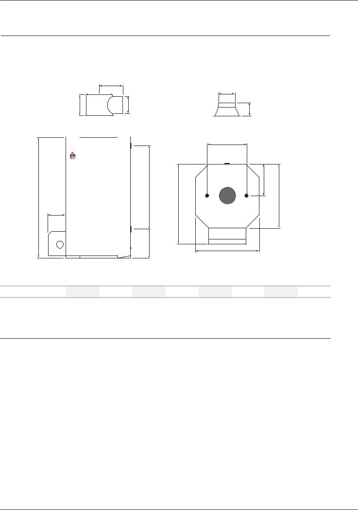
EFFECTIVE DIMENSIONS
The appliances delivered are factory-tested. Upon receipt, remove the packing and check that there is no damage to the appliances. Refer to the dimensions and weights listed below for transport purposes.
The jacket is fitted by the installer on site (see the assembly instructions in the wooden protective case).
|
|
338 |
|
|
|
|
|
|
|
|
|
|
|
|
250 |
|
|
|
302 |
|
250 |
|
|
190 |
|
|
|
|
|
|
|
|
|
|
|
|
|
|
|
|
|
F |
|
|
|
|
|
G |
|
|
|
506 |
|
|
|
|
|
|
|
|
|
|
A |
|
|
|
|
|
|
C |
|
|
|
|
|
|
|
|
|
|
|
B |
|
|
D |
|
|
|
|
|
|
|
|
|
|
|
|
|
|
|
|
H |
|
|
|
|
|
|
|
|
|
|
|
E |
|
|
|
A mm |
B mm |
C mm |
D mm |
E mm |
F mm |
G mm |
H mm |
HeatMaster® 201 |
2085 |
300 |
1020 |
1320 |
1020 |
600 |
1383 |
590 |
GENERAL CHARACTERISTICS
Type |
|
|
HM 201 |
|
Fuel |
|
|
Natural gas/propane |
|
|
|
Heating |
|
Hot water |
Maximum Input |
kW |
60 - 220 |
|
60 - 240 |
Maximum Output |
kW |
56.4 - 200.2 |
|
56.4 - 218.4 |
Maintenance loss at 60°C as rated value |
% |
|
0.3 |
|
Total capacity |
L |
|
641 |
|
Primary circuit capacity |
L |
|
241 |
|
Heating connection |
Ø |
|
2” |
|
Hot water connection |
Ø |
|
2” |
|
Chimney connection |
Ø mm |
|
250 |
|
Hot water tank heat exchange surface |
m2 |
|
5.30 |
|
Weight empty |
Kg |
|
550 |
|
Pressure drop primary circuit |
mbar |
|
240 |
|
|
|
|
|
|
6

TECHNICAL SPECIFICATION
MAXIMUM OPERATING CONDITIONS
Maximum service pressure (tank full of water)
-Primary circuit: 3 bar
-Secondary circuit: 10 bar
Test pressure (tank full of water)
-Primary circuit: 4.5 bar
-Secondary circuit: 13 bar
Operating temperature
- Maximum temperature: 90°C
Water quality
•Chlorures: < 150 mg/l (304)
<2000 mg/l (Duplex)
•6 ≤ ph ≤ 8
DOMESTIC HOT WATER PERFORMANCES
|
|
HM 201 |
|
|
|
Peak delivery at 40°C |
L/10’ |
1745 |
Peak delivery at 45°C |
L/10’ |
1489 |
Peak delivery at 60°C |
L/10’ |
971 |
Peak delivery at 70°C |
L/10’ |
763 |
Peak delivery at 80°C |
L/10’ |
586 |
|
|
|
Peak delivery at 40°C |
L/60’ |
6690 |
Peak delivery at 45°C |
L/60’ |
5667 |
Peak delivery at 60°C |
L/60’ |
3534 |
Peak delivery at 70°C |
L/60’ |
2554 |
Peak delivery at 80°C |
L/60’ |
1723 |
|
|
|
Continuous delivery at 40°C |
L/h |
6117 |
Continuous delivery at 45°C |
L/h |
5039 |
Continuous delivery at 60°C |
L/h |
2914 |
Continuous delivery at 70°C |
L/h |
2128 |
Continuous delivery at 80°C |
L/h |
1468 |
|
|
|
N.B.:
The outputs above are given for a hot water temperature of 90°C and a cold water temperature of 10°C.
HEATMASTER® SETTING INSTRUCTIONS
Description
The HeatMaster® 201 range is equipped with an electronic controller (MCBA) which controls the burner (start-up, safety, and modulation) and allows the controller to be adapted to the selected application.
The MCBA system includes a controller with 3 levels for setting the parameters: manufacturer, installer, and user. It includes 3 temperature sensors located in the primary and secondary circuits.
There are two operating modes:
1. Heating mode
The T° is set by the user in the range 60 to 90°C.
•Differential “ON” starts the burner.
•Differential “OFF” stops the burner.
•PI controller (Proportional Integral) in “Heating” mode.
•The controller compares the primary temperature with the setting and the module.
The room thermostat detects the demand for heat.
2. Hot water mode (with priority to the hot water)
The T° is set by the user in the range 60 to 90°C.
The sensor located in the secondary tank detects the demand for hot water.
As soon as the draw-off is detected, the controller goes to “demand for hot water” mode:
•Differential “ON” starts the burner.
•Differential “OFF” stops the burner.
•PI controller (Proportional Integral) in “Hot water” mode.
•The controller compares the primary temperature with the setting and the module.
•The charging pump starts up.
•The heating circulator pump is no longer supplied.
•The burner starts and the controller controls the modulation based on the primary pump.
Parameters accessible by the user
1.“Hot water” temperature, which can be set to 20 - 90°C.
2.Hot water mode ON/OFF.
3.Heating mode: ON/OFF.
4.“Heating” temperature, which can be set to 60 - 90°C.
Parameters accessible for “service”
Main basic characteristics:
-Hot water priority active.
-Demand for heat detected by the room thermostat.
-Only one heating circuit.
An access code is required to access “Service” parameters.
Please see pages 17 to 19 for further details.
7
 Loading...