

Page 1
OPERATION AND MAINTENANCE MANUAL
C-150, C-250, C-375, C-500, C-800
Model:
By SteelTech Inc.
Version 2
Serial No.:
UL 2523-2009
UL 391 (1995)
CAN/CSA B366.1-M91
Page 2

2
Page 3

Contents
Warranty and Safety
RETAIN THIS MANUAL FOR
FUTURE REFERENCE
DO NOT THROW AWAY
Limited Lifetime Warranty ......................4
Water Treatment And Testing ................... 5
Water Treatment Policy ........................5
Safety Precautions............................6
Chimney ...................................7
Installation
Location ...................................7
Furnace Foundation ..........................8
Trench .....................................8
Wiring .....................................9
Hydronic Lines...............................9
Furnace Connection .......................... 9
Operation
How it Works............................... 12
Filling The Furnace With Water .................12
Firing The Furnace...........................12
Care And Maintenance.......................14
Troubleshooting............................. 15
Electrical Schematics Ranco Control ...........17-18
Electronic Temperature Control Settings &
Specifications
Electronic Timer Control And Settings ............ 20
Unit Footprints.............................. 21
Replacement Components List .................22
.............................. 19
14
16
18-19
20
21
22
23
CANADA
SteelTech Inc.
Box 158
Winkler MB. R6W 4A5
Canada
Ph. (204) 325-9792
Fax (204) 325-9803
USA
SteelTech Inc.
Box 373
Walhalla ND. 58282
Ph. (877) 325-9792
Fax (204) 325-9803
info@heatmasterss.com
www.heatmasterss.com
heatmasterss.com 3heatmasterss.com 3
Page 4

LIMITED LIFETIME WARRANTY
SteelTech Inc. warrants to the original owner of the
SS
Heatmaster
defects in workmanship and material which could
cause a leak or malfunction of the firebox or water
jacket and against corrosion (if the instructions in the
owner’s manual for water treatment and maintenance
are followed) for The Life of the furnace toward the
purchase of a new Heatmaster
following pro-rated schedule.
outdoor furnace that it is free from
SS
furnace, in the
Warranty schedule: coverage in the initial 5
years is 100%
• Year 6-7 is 50%
• Year 8-9 is 40%
• Year 10-15 is 30%
• Year 16-Life is 10%
• Grates and Firebox door have a warranty of 5
years at 100%.
• Ash Pan is covered for corrosion protection for a
period of one year.
In addition, all steel components including housing,
legs, etc. have a pro-rated warranty for a period of
10 years with coverage reducing by 10% per year.
Any parts not manufactured by SteelTech Inc. that
are used on the furnace such as fans, aquastats, limit
switches, pumps, heat exchangers, etc carry their own
manufacturer’s warranty, normally one year. SteelTech
Inc. will not be liable for the cost of shipping, labor,
replacement or repair of these parts.
If warranty requires removal or replacement of the
furnace or a part of the furnace, SteelTech Inc. and
their dealers are not responsible for the cost of labor,
replacement of antifreeze or water treatment, shipping
cost or any other cost other than the replacement
component or furnace. SteelTech Inc. always has the
right to decide if a part or furnace will be repaired
or replaced and will not be liable for any cost not
authorized by a SteelTech Inc representative.
SteelTech Inc. does not warranty any damage caused
due to burning improper fuels such as wood, oils or
plastics, negligence and deterioration due to lack
of proper ongoing maintenance, physical damage
caused by abuse or freeze up, power surges or
unauthorized work or modifications to the furnace. It
is recommended to always have a back up heating
system installed in case of disruption in the outdoor
furnace heating system.
SteelTech Inc. is not liable for any damage or cost
which may occur from or during the operation of
the furnace or damage incurred due to any heating
system failure. The purchaser assumes all responsibility
for the care, maintenance and safe operation the
furnace including adding of approved boiler treatment
or water. SteelTech Inc doesn’t warrant door gaskets,
exterior paint or finish.
To qualify for warranty all instructions must be
followed in operator’s manual, water must be tested
and maintained a minimum of once per year, and
warranty registration must be on file at SteelTech
Inc within 30 days of purchase along with a copy of
the original invoice. No warranty can be approved
unless the warranty registration and water test
verifications are on file at SteelTech Inc.’s office.
SteelTech Inc. reserves the right to change conditions of warranty
at any time.
44
Page 5

WATER TREATMENT AND TESTING
Water Treatment Policy
To qualify for warranty, water must be tested a
minimum of once per year and water treatment added
when necessary.
To take a water sample:
1. Locate your water sample bottle, mailing carton
and mailing label provided to you by your dealer.
2. Open the boiler drain located at the bottom of
the rear of the furnace for 10-15 seconds or until
the water runs clear. CAUTION: Water is hot! Use
extreme care or a bucket to run water into and let
cool before collecting sample.
3. Fill one of the test bottles at least 1/2 to 2/3 full.
4. Fill out the mailing label provided with the test
bottle completely, including your email address, the
model number and serial number of your furnace.
Make sure to note if the furnace water contains any
antifreeze or additional chemicals.
5. Attach top part of label to sample bottle and
bottom part to outside of mailing tube. Place bottle
in tube.
6. Mail to our testing lab. Results can take up to 4
weeks to receive and up to 8 weeks if no email
address is on hand at Heatmaster
You will receive a water test report outlining
what must be done (if anything). If any action is
necessary, take another sample and mail it to our
test lab again to verify the recommended changes
have been made.
Add the water treatment through the fill pipe located
at the top of the furnace when initially filling the
furnace with water or after testing, if needed. Ensure
that all drains are closed. It is recommended that
water treatment is added at a 1:200 ratio when
initially firing the furnace, and add accordingly
based on the water test results. Additional treatment
may have to be added for water with more severe
properties or for systems with more chemically
demanding requirements.
SS.
Recommended operating levels are as
follows:
Conductivity: 100 - 4000 ppm
pH: 8.5 – 10. 5
Nitrates: no less than 730 ppm
Test Parameters and What They Mean
Conductivity
Conductivity is a measurement of minerals in your
furnace water. While it is common to have minerals in
water, in excess minerals can cause many problems in
hydronic systems including scaling and corrosion.
pH
pH is measurement of alkalinity (hard or soft water).
For outdoor furnace water and the water treatment
used in outdoor furnaces it is better to have your water
a little harder than softer (recommended pH range is
8.5-10) as the active ingredients in the water treatment
neutralize harder water easier than softer water
Nitrates
Nitrates tested for are a measurement of how much
water treatment is in the water. Nitrates measured are
active units of water treatment available to neutralize
harmful elements in your furnace water. Nitrates also
act to neutralize harmful bacteria that may build up in
the furnace water over time.
Glycol
Inhibited glycol provides anti-corrosion elements
and freeze protection for outdoor furnaces and is
compatible with Outdoor Furnace Water Treatment.
Because outdoor furnaces are open to the atmosphere
systems and will have fresh water added occasionally,
oxygen is always entering the system and will break
down the glycol over time to create glycolic acid which
will harm your furnace system. When this happens
you will be required to drain and flush your furnace
system.
It is always suggested to use 100% virgin glycol
instead of recycled glycol as it will break down much
sooner and create glycolic acid.
heatmasterss.com 5heatmasterss.com 5
Page 6

SAFETY PRECAUTIONS
Read and understand all precautions before operating
the furnace.
Save these instructions. Retain this manual as long
SS
as you own your Heatmaster
read and follow these directions.
furnace. Carefully
IMPORTANT
THESE FURNACES ARE FOR COAL BURNING ONLY.
Follow all applicable local laws.
DANGER
Do not start fire with or burn chemicals, volatile fluids,
rubber, plastics or garbage. Only competent persons
with a sound understanding of this heating method
should operate this furnace. Improper firing could
result in personal injury and or damage to the unit
and void warranty.
Risk of fire or explosion
• Do not use chemicals or fluids to start the fire.
• Do not burn garbage, gasoline, drain oil or other
flammable liquids.
• Do not operate with fuel loading or ash removal
doors open
• Do not store fuel or other combustible material
within marked installation clearances
• Inspect and clean flues and chimney regularly
• Maximum draft marked on nameplate
• DO NOT CONNECT THIS UNIT TO A CHIMNEY FLUE
SERVING ANOTHER APPLIANCE
WARNING
• All installations and operations of your
HEATMASTER SS product must follow STATE,
PROVINCIAL, and LOCAL LAWS pertaining to
operations, wiring, plumbing and building codes.
• All models operate at atmospheric pressure. DO
NOT obstruct, block or plug the overflow vent tube
in any way which is located on top of the boiler
either in front of or behind the chimney.
• When installing the furnace, the chimney should
never be connected to a chimney flue serving
another appliance.
• Do not start a fire in the furnace without first filling
with water. It will cause serious damage to the
furnace.
• All covers or guards must be in place at all times,
except for maintenance or service.
ATTENTION
• A copy of the owner’s manual in French is
SS
available by request from Heatmaster
• The person(s) operating this furnace must comply
with all applicable local and state laws or other
requirements,
• Do not remove labels from furnace except in the
case of servicing.
offices.
CAUTION
• Use of an approved spark arrester is
recommended. It is the recommendation of
SteelTech Inc that a 15’ minimum distance of
clearance from buildings and other combustibles.
Your local authorities and your insurance company
may require a greater distance. Never allow
combustible material to accumulate near the unit.
Fuel should never be stored where there is the
potential for accidental fire.
• Load carefully or damage will result.
• Do not use chemicals or fluids to start the fire.
• Do not start or operate furnace without checking
heating fluid. Furnace must be filled until heating
fluid comes out of vent pipe on the top of the
furnace.
• Hot Surfaces: Keep children away. Do not touch
during operation.
RECOMMENDED
Choose the location of your furnace with concerns of
wind direction, smoke odor, sparks, blocked viewing
and fuel storage carefully. Be a responsible and
considerate owner.
66
Page 7
Chimney
The chimney on your HeatMasterSS outdoor furnace is
a stainless steel double wall insulated chimney. It is
attached to the furnace with a stainless steel adapter.
To install chimney extensions be sure to purchase the
same chimney as on your furnace (Selkirk Ultra Temp).
These chimneys are a twist lock connect chimney.
Be sure to use the chimney fastening ring to fasten
the connection tight. Braces, elbow kits and roof
flashing kits are available through your dealer. It is not
recommended that the chimney be longer than 15 ft.
Do not connect this unit to a chimney flue serving
another appliance.
The chimney and flue pipe need to be kept clean and
in good condition. See below for chimney sizes.
• C-150 - 6” Stainless Steel Double Wall Chimney and
Adapter
• C-250 – 6” Stainless Steel Double Wall Chimney
and Adapter
• C-375 – 6” Stainless Steel Double Wall Chimney
and Adapter
• C-500 – 8” Stainless Steel Double Wall Chimney
and Adapter
• C-800 – 10” Stainless Steel Double Wall Chimney
and Adapter
NOTE : Chimney extensions and caps are useful for
lifting exhaust gases and smoke away from buildings.
However, when burning a C Series furnace keep in
mind that the cooler exhaust temperatures as a result
of the high efficiency burn of these furnaces may cause
excess condensation when chimney extensions and
caps are used. This can lead to improper burning in the
furnace. A taller chimney also greatly increases the risk
of overheating due to the extra draft created caused by
the negative pressure put on the firebox. Extra care must
then be taken to minimize air leakage into the firebox.
FURNACE INSTALLATION GUIDE
Installation should be performed by a qualified technician. THESE FURNACES ARE FOR COAL USE ONLY.
FOLLOW ALL APPLICABLE LOCAL LAWS
LOCATION
Maintain adequate clearance of buildings and
combustibles. Store fuel outdoors under cover. Do
not place or store fuel or allow debris to accumulate
within stove installation clearances or within the space
required for charging and ash removal. Never install
the furnace in the fuel storage building.
CLEARANCES TO COMBUSTIBLES
Whether installing your furnace inside a building or
outside, the following clearances to combustibles must
always be followed. Damage and personal injury may
result.
DO NOT STORE COMBUSTIBLE FUELS IN THE SAME
SPACE AS THE FURNACE IF INSTALLED INDOORS.
Contact all governing authorities in your area prior to
installation.
When choosing the location of your furnace you should
consider prevailing wind direction, distance from home
for refueling and fuel storage and give consideration
for any effect on your neighbors.
Minimum Clearance to Combustibles
Sidewall to Furnace 0”
Back Wall to Furnace 36”
Front of Furnace 36”
heatmasterss.com 7heatmasterss.com 7
Page 8
FURNACE FOUNDATION
• Inspect the ground conditions that you intend to
install your furnace on. If the area is unstable
or has a history of staying wet you may have to
improve the soil with gravel as well as raise the
level of furnace placement.
• A cement pad of 4-6” in thickness should be used.
• The furnace in most cases can be placed on 4
cement blocks not less than 6” wide X 10” long
and 3” thick.
• The furnace should never be installed on a
combustible floor.
• Never allow combustible material to accumulate on
the furnace foundation.
• Do not install on a combustible base
Find the footprint of the furnace you have purchased
in the appendix of this manual and place your blocks
so the legs will stand on the center of the blocks.
Cement pads should be a little bigger than the actual
furnace, with about a 4’ extra length front and back so
you have a solid working area.
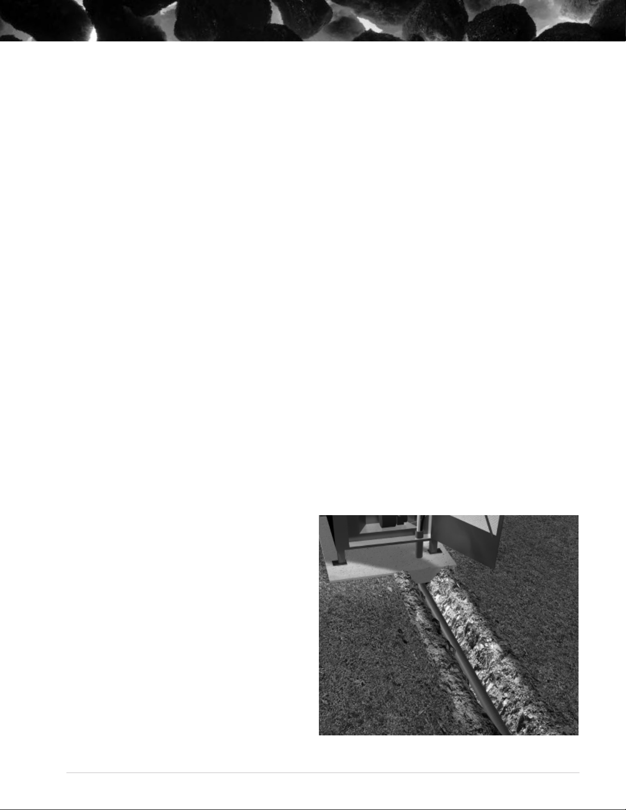
If possible, have a gradual slope in your trench to
allow drainage away from your lines and out of
trench bottom. Most insulated underground pipe
has room for electrical wire in it. If it does not, place
electrical supply in bottom of trench and cover with
6 inches of dirt. A minimum of R8 insulation value is
recommended and a water tight vapor barrier such
as PVC pipe or drain tile to encase your insulation is a
must.
NOTE : It is recommended that only high quality,
well insulated lines are used. Poor quality casing or
insulation can deteriorate over time causing heat loss
in the ground and loss of efficiency in your system.
Purchase your insulated line from a reputable source.
Your Heatmaster
SS
dealer will carry high quality
insulated line and can help you determine the best line
to purchase.
NOTE : If you are installing your water lines under an
area where vehicles will cross, you should increase your
depth of the trench and use a schedule pipe over your
lines to reduce the pressure generated on the lines.
FURNACE FOUNDATION
ever allow combustible material to accumulate on
If possible, have a gradual slope in your trench to
allow drainage away from your lines and out of
trench bottom. Most insulated underground pipe
has room for electrical wire in it. If it does not, place
electrical supply in bottom of trench and cover with
6 inches of dirt. A minimum of R8 insulation value is
recommended and a water tight vapor barrier such
as PVC pipe or drain tile to encase your insulation is a
must.
NOTE : It is recommended that only high quality,
well insulated lines are used. Poor quality casing or
insulation can deteriorate over time causing heat loss
in the ground and loss of efficiency in your system.
Purchase your insulated line from a reputable source.
Your Heatmaster
SS
dealer will carry high quality
insulated line and can help you determine the best line
FURNACE FOUNDATION
• Inspect the ground conditions that you intend to
install your furnace on. If the area is unstable
or has a history of staying wet you may have to
improve the soil with gravel as well as raise the
level of furnace placement.
• A cement pad of 4-6” in thickness should be used.
• The furnace in most cases can be placed on 4
cement blocks not less than 6” wide X 10” long
and 3” thick.
• The furnace should never be installed on a
combustible floor.
• Never allow combustible material to accumulate on
the furnace foundation.
• Do not install on a combustible base
Find the footprint of the furnace you have purchased
and place your blocks
furnace, with about a 4’ extra length front and back so
If possible, have a gradual slope in your trench to
allow drainage away from your lines and out of
trench bottom. Most insulated underground pipe
has room for electrical wire in it. If it does not, place
electrical supply in bottom of trench and cover with
6 inches of dirt. A minimum of R8 insulation value is
recommended and a water tight vapor barrier such
as PVC pipe or drain tile to encase your insulation is a
must.
NOTE : It is recommended that only high quality,
well insulated lines are used. Poor quality casing or
insulation can deteriorate over time causing heat loss
in the ground and loss of efficiency in your system.
Purchase your insulated line from a reputable source.
Your Heatmaster
SS
dealer will carry high quality
insulated line and can help you determine the best line
to purchase.
NOTE : If you are installing your water lines under an
area where vehicles will cross, you should increase your
depth of the trench and use a schedule pipe over your
lines to reduce the pressure generated on the lines.
• Inspect the ground conditions that you intend to
install your furnace on. If the area is unstable
or has a history of staying wet you may have to
improve the soil with gravel as well as raise the
level of furnace placement.
• A cement pad of 4-6” in thickness should be used.
• The furnace in most cases can be placed on 4
cement blocks not less than 6” wide X 10” long
and 3” thick.
• The furnace should never be installed on a
combustible floor.
• N
the furnace foundation.
• Do not install on a combustible base
• A non combustible material such as cement or
steel should be used under the boiler and at
least 16 inches (400 mm) in front and 8 inches
(200 mm) on either side of the fuel-loading and
ash removal doors.
in the appendix of this manual
so the legs will stand on the center of the blocks.
Cement pads should be a little bigger than the actual
you have a solid working area.
8
TRENCH
SteelTech Inc recommends the trench to be 24” to
36” deep and wide enough to install your water
lines. Take into consideration soil conditions as rocky
soil conditions can cause the casing of the pipe to
be damaged and allow water to fill the pipe. If soil
conditions require, fill the trench with sand.
If possible, have a gradual slope in your trench to
allow drainage away from your lines and out of
trench bottom. Most insulated underground pipe
has room for electrical wire in it. If it does not, place
electrical supply in bottom of trench and cover with
6 inches of dirt. A minimum of R8 insulation value is
recommended and a water tight vapor barrier such
as PVC pipe or drain tile to encase your insulation is a
must.
NOTE : It is recommended that only high quality,
well insulated lines are used. Poor quality casing or
insulation can deteriorate over time causing heat loss
in the ground and loss of efficiency in your system.
Purchase your insulated line from a reputable source.
SS
Your Heatmaster
dealer will carry high quality
insulated line and can help you determine the best line
to purchase.
NOTE : If you are installing your water lines under an
area where vehicles will cross, you should increase your
depth of the trench and use a schedule pipe over your
lines to reduce the pressure generated on the lines.
Page 9

WIRING
HYDRONIC LINES
All wiring must conform to local codes. Use an
electrical wire rated and approved for underground
installations. This wiring can be placed in the same
trench below the water lines. It is recommended that
a qualified technician be present when installing the
electrical portion of the hook-up.
See Pages 17-18 for the furnace wiring diagrams.
FURNACE CONNECTION
Connections to the furnace are clearly marked.
Return (from the building) are the top ports, Supply
(to the building) are the bottom ports. The installation
of isolation valves at both ends of the pump is
recommended as well as a valve at the return line.
This will allow you to shut off water supply if repairs
Hydronic lines (hot water heating lines) whenever
buried or encased in cement should not be spliced.
Take the necessary steps to ensure they stay dry. This
ensures that minimal heat loss occurs. Supply and
return lines should be a minimum of ¾” diameter,
although 1” is most common, and have a rating of
100 PSI capacity at 180 degrees Fahrenheit. This pipe
should be listed for potable water.
Hint: Mark your feed and return lines prior to covering
and allow enough pipe above ground at both ends
for a relaxed connection. Red lines are generally “hot”
while blue are usually “cold”.
or additional heating components are added to the
system. Your main power is connected to the junction
box at the back of furnace and should be connected
by a qualified technician.
NOTE : A supply of fresh air is necessary for
combustion and ventilation. Do not block fresh air
intake located at the back of the furnace.
COMBUSTION FAN
SOLENOID
FURNACE DRAIN VALVE
PUMP PLUG IN AND
FURNACE POWER
SWITCH
LEAD IN POWER
JUNCTION BOX
TIMER
CIRCULATION PUMP
ADJUSTABLE AIR
BLOWER BOX
UNDERGROUND
PIPE
heatmasterss.com 9heatmasterss.com 9
Page 10

• Do not relocate or bypass any of the safety controls
in the original (gas, oil, electric) boiler installation.
• The operation of the gas boiler must be verified for
acceptable operation before and after installation
of the add-on appliance by a gas fitter who is
recognized by the regulatory authority.
• Do not connect to any chimney or vent serving a
gas appliance.
The installation should comply with requirements
of CAN/CSA-B365, and changes to the installation
should comply with CSA B139 (for oil-fired), C22.1 (for
electric), or CAN/CGA-B149.1 or CAN/CGA-B149.2 (for
gas-fired).
Any installation of an add-on boiler shall:
• be installed without interfering with the normal
delivery of heated water from the original boiler,
• be installed without affecting the operation of the
electrical and mechanical safety controls of the
original boiler,
• provide for a changeover from one fuel to the other
without requiring manual adjustment of any controls
or components other than the thermostats,
• have provisions for preventing, or adequate water
capacity within the boiler to prevent damage from
loss of circulation due to electrical power failure,
• be installed without changing the function of the
controls or rewiring the original boiler. A wiring
interconnection is permitted. The electrical system
of both boilers shall be powered from a single
branch circuit without exception.
At least one pump must be circulating at all times or
• Do not relocate or bypass any of the safety controls
in the original (gas, oil, electric) boiler installation.
• The operation of the gas boiler must be verified for
acceptable operation before and after installation
of the add-on appliance by a gas fitter who is
recognized by the regulatory authority.
• Do not connect to any chimney or vent serving a
gas appliance.
The installation should comply with requirements
of CAN/CSA-B365, and changes to the installation
should comply with CSA B139 (for oil-fired), C22.1 (for
electric), or CAN/CGA-B149.1 or CAN/CGA-B149.2 (for
gas-fired).
Any installation of an add-on boiler shall:
• be installed without interfering with the normal
delivery of heated water from the original boiler,
• be installed without affecting the operation of the
electrical and mechanical safety controls of the
original boiler,
• provide for a changeover from one fuel to the other
without requiring manual adjustment of any controls
or components other than the thermostats,
• have provisions for preventing, or adequate water
At least one pump must be circulating at all times or
the water in the furnace may boil. A continuous pump
is also useful for freeze protection in temperatures
below 32 degrees F.
It is important to calculate the BTU’s needed, line size,
flow rate and return water temperature to determine
what size circulating pump is needed. Undersized lines
or long distance piping can reduce flow dramatically.
The best place to mount the main pump is on the
supply outlet. Placing the pump inside the building can
lead to cavitation and air-lock problems.
Building Connections
A hole large enough to accommodate the water
lines, insulation and PVC piping through is important.
Attention to sealing this point with a weather proof
insulation on both sides is also important.
Interior Connections
You may require either a water-to-water (tube and
shell or plate) or a water-to-air exchanger (rad) to
transfer heat energy from the hot water your furnace
has produced. Your plumber or dealer can design and
install a system to best fit your needs.
• Do not relocate or bypass any of the safety controls
in the original (gas, oil, electric) boiler installation.
• The operation of the gas boiler must be verified for
acceptable operation before and after installation
of the add-on appliance by a gas fitter who is
recognized by the regulatory authority.
• Do not connect to any chimney or vent serving a
gas appliance.
The installation should comply with requirements
of CAN/CSA-B365, and changes to the installation
should comply with CSA B139 (for oil-fired), C22.1 (for
electric), or CAN/CGA-B149.1 or CAN/CGA-B149.2 (for
gas-fired).
Any installation of an add-on boiler shall:
• be installed without interfering with the normal
delivery of heated water from the original boiler,
• be installed without affecting the operation of the
electrical and mechanical safety controls of the
original boiler,
• provide for a changeover from one fuel to the other
without requiring manual adjustment of any controls
or components other than the thermostats,
• have provisions for preventing, or adequate water
capacity within the boiler to prevent damage from
loss of circulation due to electrical power failure,
• be installed without changing the function of the
controls or rewiring the original boiler. A wiring
interconnection is permitted. The electrical system
of both boilers shall be powered from a single
branch circuit without exception.
At least one pump must be circulating at all times or
the water in the furnace may boil. A continuous pump
is also useful for freeze protection in temperatures
below 32 degrees F.
It is important to calculate the BTU’s needed, line size,
flow rate and return water temperature to determine
what size circulating pump is needed. Undersized lines
or long distance piping can reduce flow dramatically.
The best place to mount the main pump is on the
supply outlet. Placing the pump inside the building can
lead to cavitation and air-lock problems.
Building Connections
A hole large enough to accommodate the water
lines, insulation and PVC piping through is important.
Attention to sealing this point with a weather proof
insulation on both sides is also important.
Interior Connections
You may require either a water-to-water (tube and
shell or plate) or a water-to-air exchanger (rad) to
transfer heat energy from the hot water your furnace
has produced. Your plumber or dealer can design and
install a system to best fit your needs.
IMPORTANT: It is recommended to always have a
back up heating system installed in case of disruption
in the outdoor furnace heating system.
The following are examples of basic interior
connections. SteelTech Inc. carries the necessary parts
for installation. Contact us for more information!
DISCLAIMER: The following information in the interior
connections are examples and suggestions only. When
installing a furnace and its parts it is best to talk to
your local dealer or a qualified technician.
Water-To-Water Heat Exchangers
To maintain pressure in an existing boiler while using
an outdoor furnace a water-to-water heat exchanger is
used. The water-to-water exchanger is installed in-line
on the return side of the existing pressurized boiler
system.
• Do not relocate or bypass any of the safety controls
in the original (gas, oil, electric) boiler installation.
• The operation of the gas boiler must be verified for
acceptable operation before and after installation
of the add-on appliance by a gas fitter who is
recognized by the regulatory authority.
• Do not connect to any chimney or vent serving a
gas appliance.
The installation should comply with requirements
of CAN/CSA-B365, and changes to the installation
should comply with CSA B139 (for oil-fired), C22.1 (for
electric), or CAN/CGA-B149.1 or CAN/CGA-B149.2 (for
gas-fired).
Any installation of an add-on boiler shall:
• be installed without interfering with the normal
delivery of heated water from the original boiler,
• be installed without affecting the operation of the
electrical and mechanical safety controls of the
original boiler,
• provide for a changeover from one fuel to the other
without requiring manual adjustment of any controls
or components other than the thermostats,
• have provisions for preventing, or adequate water
capacity within the boiler to prevent damage from
loss of circulation due to electrical power failure,
• be installed without changing the function of the
controls or rewiring the original boiler. A wiring
interconnection is permitted. The electrical system
of both boilers shall be powered from a single
branch circuit without exception.
the water in the furnace may boil. A continuous pump
is also useful for freeze protection in temperatures
below 32 degrees F.
It is important to calculate the BTU’s needed, line size,
flow rate and return water temperature to determine
what size circulating pump is needed. Undersized lines
or long distance piping can reduce flow dramatically.
The best place to mount the main pump is on the
supply outlet. Placing the pump inside the building can
lead to cavitation and air-lock problems.
Building Connections
A hole large enough to accommodate the water
lines, insulation and PVC piping through is important.
Attention to sealing this point with a weather proof
insulation on both sides is also important.
Interior Connections
You may require either a water-to-water (tube and
shell or plate) or a water-to-air exchanger (rad) to
transfer heat energy from the hot water your furnace
has produced. Your plumber or dealer can design and
install a system to best fit your needs.
IMPORTANT: When installing a piping system in your
building that you should avoid installation methods
that cause too great a restriction in the piping
system. Examples of this are reducing pipe size, an
excessive amount of joints and elbows, etc.
IMPORTANT: It is recommended to always have a
back up heating system installed in case of disruption
in the outdoor furnace heating system.
The following are examples of basic interior
connections. SteelTech Inc. carries the necessary parts
for installation. Contact us for more information!
DISCLAIMER: The following information in the interior
connections are examples and suggestions only. When
installing a furnace and its parts it is best to talk to
your local dealer or a qualified technician.
Water-To-Water Heat Exchangers
To maintain pressure in an existing boiler while using
an outdoor furnace a water-to-water heat exchanger is
used. The water-to-water exchanger is installed in-line
on the return side of the existing pressurized boiler
system.
10
• Operate the (gas, oil, electric) boiler periodically
to ensure that it will operate satisfactorily when
needed.
• Do not relocate or bypass any of the safety controls
in the original (gas, oil, electric) boiler installation.
• The operation of the gas boiler must be verified for
acceptable operation before and after installation
of the add-on appliance by a gas fitter who is
recognized by the regulatory authority.
• Do not connect to any chimney or vent serving a
gas appliance.
The installation should comply with requirements
of CAN/CSA-B365, and changes to the installation
should comply with CSA B139 (for oil-fired), C22.1 (for
electric), or CAN/CGA-B149.1 or CAN/CGA-B149.2 (for
gas-fired).
Any installation of an add-on boiler shall:
• be installed without interfering with the normal
delivery of heated water from the original boiler,
• be installed without affecting the operation of the
electrical and mechanical safety controls of the
original boiler,
• provide for a changeover from one fuel to the other
without requiring manual adjustment of any controls
or components other than the thermostats,
• have provisions for preventing, or adequate water
capacity within the boiler to prevent damage from
loss of circulation due to electrical power failure,
• be installed without changing the function of the
controls or rewiring the original boiler. A wiring
interconnection is permitted. The electrical system
of both boilers shall be powered from a single
branch circuit without exception.
Heat exchanger with boiler
Page 11

INTERIOR CONNECTIONS (continued)
Forced Air Furnace (Water-To-Air Exchanger)
When circulation is reduced because of an electrical
power failure the installation of a hot-water
circulation loop that will dissipate at least 10% of the
estimated rated heat output of the solid-fuel boiler is
recommended with the following guidelines:
• The loop can only be made inoperative by a
deliberate manual action.
• The design parameters for sizing shall be a pipe
size > 3/4 inch (18 mm), room temperature of 65°
F (18° C), and mean water temperature of 180° F
(82° C).
• The loop be positioned above the boiler, with
features that promote natural thermal circulation of
the water.
The piping used in the system should not cause any
restrictions that could create excessive pressure in the
system. Eg. Reducing from 1” pipe to ½” pipe
Flat Plate Exchanger For Pressurized
Systems
Flat plate exchanger systems that are used with
pressurized systems such as in floor heating or hot
water baseboard systems help to heat the water
going in to the pressurized system while keeping the
two systems separate. Because an outdoor furnace
is an open system (not pressurized) and the system
tied in to in this type of application is pressurized it
allows both systems to stay the same while being
operational.
The water-to-air heat exchanger must be mounted so
that air blows through the fins (coils). The exchanger
should be mounted below the A/C coil if possible.
The exchanger should be sized to fit existing duct
work and should produce about as many BTU’s as
the existing heat source. An exchanger that produces
too many BTU’s will result in uneven heat and the fan
stopping too quickly while a heat exchanger that is
undersized will not produced the necessary BTU’s.
On systems with Air Conditioning it is very important
to not restrict airflow as it will cause the freon coil to
freeze up. Using standard outdoor furnace 3 row coils,
a minimum of 80 sq. in. of coil should be used per
ton of cooling. Exchangers can be mounted in cold
air returns but greater care must be taken as heat
from the exchanger can interfere with the air handler
controls and/or sensors.
It is important that the warm-air supply-duct system be
constructed of metal in accordance with NFPA 90B1993, 2-1.1 if the outlet-air temperature of a central
furnace exceeds 250° F (121° C) when it is tested in
accordance with the requirements for Simultaneous
Firing in 56.4.1 and 56.4.2 of the standard. It is also
important that the plenums installed to the furnaces be
constructed of metal in accordance with NFPA 90B1993, 2-1.3.
The water supplied by the outdoor furnace will heat
the water in the pressurized system while the present
heat source in the pressurized system (such as a
boiler) can be used as a back up heat source in case
of emergency or need for additional heat.
Domestic Hot Water
Flat plate exchanger systems used to pre-heat
domestic water tanks are generally easier to install,
more efficient and more reactive to hot water
demands then tube and shell (sidearm) systems. They
are mounted on the supply line and pre-heat the
water going in to the hot water tank.
Forced air furnace with water-to-air exchanger
heatmasterss.com 11heatmasterss.com 11
Page 12

OPERATING THE FURNACE
HOW IT WORKS
The C Series furnace is a 409 stainless steel outdoor
furnace with a water jacket surrounding the firebox.
This reservoir of hot water is pumped through
insulated lines to buildings, pools, greenhouses or
whatever is being heated.
Fuel is loaded in the firebox and the aquastat senses
the water temperature, sending power to the solenoid
and draft fan when the water temperature gets too low.
When the furnace calls for heat, the solenoid opens
the draft flap in the blower box and the fan blows air
through the box and under the grates cooling them
even during a hot burn.
The majority of the air enters the firebox through the
grates and coal bed creating a very hot burn but
some also is forced up through the secondary air vent.
This helps burn off the gases, increasing efficiency
and reducing smoke.
After leaving the top of the firebox the exhaust is
forced to scrub the water jacket while traveling
through the curved baffle, then goes up through water
jacket, impacting the top bypass baffle, traveling
all the way to the front, then to the back and up the
chimney. This triple pass is a simple and very effective
heat exchanger, lowering exhaust temperatures and
also extinguishing sparks as they travel back and forth
over the long distances. The C800 model utilizes a
double instead of a triple pass.
When the aquastat senses the water is up to the
high temperature setting, it shuts off the fan and the
solenoid drops.
The furnaces is normally loaded every 12-24 hours and
ashes are removed when needed using the ash rake,
shaker grate and ash pan.
FILLING THE FURNACE WITH WATER
Your furnace has a vent pipe that protrudes through
the roof and contains the water level float indicator.
The float level can vary an inch or so depending on
the water temperature. Add water when it reaches
half way down the gauge. Allowing the furnace to run
low on water will cause the furnace to overheat and
cause damage to the furnace.
It can also potentially cause
a fire hazard. This is an open
system so the unit cannot be
pressurized. If you overheat and
boil the water in the furnace
immediately refill the tank, then
try to find the source of the
problem.
Hint: Although water can be
filled using the vent pipe, it is
recommended that a fill valve
be installed inline in the building
you’re heating with a one way check valve to prevent
back flow. Filling the furnace with the inline valve
pushes all the air towards the furnace and out of
the vent. Because this furnace is an open system it is
normal that water will have to be added annually.
CAUTION: Do not fire furnace until it is filled with
water. Allow furnace to run for 2 days and check
system water levels and fittings for leaks. Add water
treatment and take your initial water sample at this
SS
time and be sure that it is sent in to Heatmaster
offices for testing.
FIRING THE FURNACE
These furnaces have been specifically designed to
burn coal and as such, are not intended for burning
any other fuels such as wood, rubber, oil, plastic or
garbage. Burning these fuels in your furnace will result
in the warranty on the furnace being voided.
It is a violation of the 2015 EPA New Source
Performance Standards for Residential Heaters to
burn unapproved fuel in this outdoor furnace
WARNING - Risk of Fire
• Do on operate with fuel loading or ash removal
doors open.
• Do not store fuel or other combustible material
within marked installation clearances.
• Inspect and clean flues and chimney regularly.
CAUTION - Hot Surfaces
Keep children away. Do not touch during operation.
1212
Page 13

Coal
GRATES OPEN
When initially firing add a small amount of paper and
wood kindling to start the fire and create a coal bed.
Once a sufficient coal bed has been developed, add
coal gradually until a suitable fire is achieved then
add coal as needed to bring up the fire.
Load the furnace twice a day
ATTENTION: On the initial start up the water jacket
will reach what is called the dew point. This creates a
sweating inside the fire box and water to collect in the
ash drawer and on the door jamb which may last a
couple of days and is normal.
Loading
1. Once a hot coal bed is established, load a deep
pile of coal towards the back of the firebox no
higher than the bottom edge of the door jamb.
2. Be sure to leave a small air hole at the front of
the pile (near the secondary air vent) to maintain
enough airflow up through the grate.
3. Load only what you need for the next 12-24 hours
as overloading the furnace is much less efficient.
4. DO NOT pile coal above the bottom edge of the
door jamb. It will choke out the draft and sporadic
flashing may occur.
Hint: Although everyone has different methods of
firing, it is worth mentioning that adding and filling
your furnace to capacity reduces the efficiency of the
furnace. It is better to load twice a day with less fuel
than once a day filling to capacity. Smaller fuel loads
burn hotter, cleaner and more thoroughly. By burning
off more of the gases (smoke), you enhance the over
all efficiency of your system and increasing heat
transfer to the water.
Coal varies widely depending on the type of coal and
properties of the seam that it was mined from (ash
content, clinkering, BTU output, etc.). Some adjustment
in firing methods such as banking the coal differently,
adjusting the timer settings, varying the amount of
coal loaded, etc is normal because of this. If you
experience difficulty after trying different methods, it
may be helpful to try coal from a different source.
CAUTION: Be very cautious when opening the firebox
door to refuel. Coal generates very explosive gases
and opening the firebox door introduces oxygen that
can cause the gases to flash. Always turn off the draft
fan (Furnace On/Off Switch on Control Panel) and
open the door to the second latch point to allow it to
vent the gases for at least 15 seconds. Only open the
door up when you are sure it is safe to do so, keeping
your face and body well away from, below and
behind the door.
Only open the door long enough to refuel. A door
left open too long can cause the fire to flame up,
endangering yourself and damaging the furnace.
Cleaning and Removing Ash and Clinkers
Cleaning and Removing Ash and Clinkers
Occasional breaking up of the crust that forms on top
Occasional breaking up of the crust that forms on top of
of the fuel load may be needed. When the pile burns
the fuel load may be needed. When the pile burns down,
down, stir the pile and shake the grates just enough to
stir the pile and shake the grates just enough to let the fine
let the fine ash fall through.
ash fall through. Use the Shaker Grate Handle to rattle the
Do not try to force all the clinkers through the grate
grates and let ash and fine particles only to fall through,
as it may cause it to jam. It is better to allow some to
leaving coals and unburned fuel on top of the grate with
accumulate, let the fire to burn down, and lift them out
access to air for proper burning. Allowing a small amount
of ash to accumulate on either side of the grate will keep
the door with a shovel. Too many clinkers can cause
the fire lit better on mild days, but be sure to keep the
the fire to slow down and choke. If clinkers accumulate
center of the grate open so the burn rate is correct.
too quickly you may have poor quality coal.
Allowing a small amount of ash to accumulate on
either side of the grate will keep the fire lit better on
mild days, but be sure to keep the center of the grate
open so the burn rate is correct.
Always empty the ashes after shaking them down. If
any hot coals are shaken down they can ignite when
the draft comes back on and create a super-heated
environment in the ash pan. This can cause the ash
pan and grates to warp and is not covered under
warranty. Always lift the ash pan slightly as you slide
it in so the front edge scrapes the ash box clean. This
will keep the pan level and prevent air leakage. Be
sure ash pan is closed tightly before you leave.
Some coal smolders better during off cycles than
others. Shortening the differential on the Ranco
temperature control to make it cycle more often can
help but is a less efficient burn.
Cleaning any ash in the bypass baffles is important.
Ash or creosote buildup can slow the burn rate and
reduce heat transfer to the water. The curved baffle
inside the firebox can be swept forward into the
Shaker
Grate
Handle
heatmasterss.com 13heatmasterss.com 13
Page 14

Always empty the ashes after shaking them down. If
GRATES OPEN
GRATES OPEN
any hot coals are shaken down they can ignite when
the draft comes back on and create a super-heated
environment in the ash pan. This can cause the ash pan
and grates to warp and is not covered under warranty.
Always lift the ash pan slightly as you slide it in so the
front edge scrapes the ash box clean. This will keep the
pan level and prevent air leakage. Be sure ash pan is
closed tightly before you leave.
Shaker Grate Dump Mode
Do not try to force all the clinkers through the grate as it
may cause it to jam. To remove clinkers, stones or large
amount of ash, use the Dump feature. To use the Dump
feature:
1. Let the fire burn down so as to not dump coals and
unburned fuel in to the ash pan
2. Open the ash drawer a minimum of 1”
3. Shake the Shaker Grate Handle using the full range
to tilt the grates back and forth up to 45⁰ to dump
ash and clinkers in to the ash pan.
4. Close the ash drawer tightly.
If clinkers are too large to dump through the grates in
to the ash pan allow some to accumulate, let the fire
to burn down, and lift them out the door with a shovel.
Too many clinkers can cause the fire to slow down and
choke. If clinkers accumulate too quickly you may have
poor quality coal.
Some coal smolders better during off cycles than others.
Shortening the differential on the Ranco temperature
control to make it cycle more often can help but is a less
efficient burn.
Cleaning any ash in the bypass baffles is important. Ash
or creosote buildup can slow the burn rate and reduce
heat transfer to the water. The curved baffle inside the
firebox can be swept forward into the firebox. It can also
be removed by bending the tabs on the front right and
left corners down and sliding it forward. The top bypass
divider can slide completely out which will give plenty of
room to drag any ash forward and out the top clean-out
door (there is no divider in the C800 model). Be sure to
replace it right-side up as it will not allow airflow through
upside down. If wet creosote accumulates in the top
of the chimney the burn rate is probably too slow and
adjustments in loading, burn times or burn rate may be
necessary to prevent the furnace airways from becoming
blocked.
14
Page 15

firebox. It can also be removed by bending the tabs
on the front right and left corners down and sliding it
forward. The top bypass divider can slide completely
out which will give plenty of room to drag any ash
forward and out the top clean-out door (there is
no divider in the C800 model). Be sure to replace
it right-side up as it will not allow airflow through
upside down. If wet creosote accumulates in the top
of the chimney the burn rate is probably too slow and
adjustments in loading, burn times or burn rate may
be necessary to prevent the furnace airways from
becoming blocked.
CONTROLS AND SAFETY DEVICES
C Series furnace
maintain your water temperature by lifting a solenoid
Solenoid - The solenoid is located beside the black
metal airbox mounted on the rear of the furnace
and is a mechanical part that opens or closes the
air injection port. The solenoid should lift when the
furnace is calling for heat and lower when the furnace
has reached its desired temperature.
Draft Fan - The draft fan is located at the rear of the
furnace on top of the black metal airbox and is used
to inject air in to the furnace. The fan should be on
whenever the furnace is calling for heat.
Timer – The timer is located in the rear of the furnace
near the lead in power box. It can be set using the
instructions on page 21 of this manual to turn the
draft fan on in set intervals to keep the coal bed alive
during times of idle.
High Limit Switch - The high limit cut off switch is
used to ensure the furnace does not cause damage
via runaway fire. It acts as a safety switch by cutting
power off to the fan if the water temperature rises
above 190° F.
Solenoid - The solenoid is located beside the black
metal airbox mounted on the rear of the furnace
and is a mechanical part that opens or closes the
air injection port. The solenoid should lift when the
furnace is calling for heat and lower when the furnace
has reached its desired temperature.
transfer.
firebox. It can also be removed by bending the tabs
on the front right and left corners down and sliding it
forward. The top bypass divider can slide completely
out which will give plenty of room to drag any ash
forward and out the top clean-out door (there is
no divider in the C800 model). Be sure to replace
it right-side up as it will not allow airflow through
upside down. If wet creosote accumulates in the top
of the chimney the burn rate is probably too slow and
adjustments in loading, burn times or burn rate may
be necessary to prevent the furnace airways from
becoming blocked.
CONTROLS AND SAFETY DEVICES
Furnace Control - Your HeatmasterSS C Series furnace
uses a factory-programed aqua stat control to
maintain your water temperature by lifting a solenoid
to open the air way and engaging the draft fan. The
control is located around the corner to the left of the
firebox door and displays the water temperature
in your furnace. Programming and troubleshooting
instructions can be found on page 20 of this manual.
Solenoid - The solenoid is located beside the black
metal airbox mounted on the rear of the furnace
and is a mechanical part that opens or closes the
air injection port. The solenoid should lift when the
furnace is calling for heat and lower when the furnace
has reached its desired temperature.
Draft Fan - The draft fan is located at the rear of the
furnace on top of the black metal airbox and is used
to inject air in to the furnace. The fan should be on
whenever the furnace is calling for heat.
Timer – The timer is located in the rear of the furnace
near the lead in power box. It can be set using the
instructions on page 21 of this manual to turn the
draft fan on in set intervals to keep the coal bed alive
during times of idle.
High Limit Switch - The high limit cut off switch is
used to ensure the furnace does not cause damage
via runaway fire. It acts as a safety switch by cutting
power off to the fan if the water temperature rises
above 190° F.
Furnace Control - Your Heatmaster
uses a factory-programed aqua stat control to
to open the air way and engaging the draft fan. The
control is located around the corner to the left of the
firebox door and displays the water temperature
in your furnace. Programming and troubleshooting
instructions can be found on page 20 of this manual.
Solenoid - The solenoid is located beside the black
metal airbox mounted on the rear of the furnace
and is a mechanical part that opens or closes the
air injection port. The solenoid should lift when the
furnace is calling for heat and lower when the furnace
has reached its desired temperature.
To obtain the high levels of performance of your
furnace, certain maintenance procedures are required
periodically to avoid soot, creosote and ash buildup.
On a daily basis you need to:
• Check for ash and creosote buildup until
experience shows how often cleaning is
necessary.
• Ensure that the door gasket is sealing properly.
• Ensure that door and ash drawer are closed and
sealing properly.
• Check water level.
• Check for sparks or coals that may have fallen
from the furnace and make sure they are safely
disposed of.
On a weekly basis you need to
• Remove ashes.
• Check for ash and creosote build up in the bypass
trough, top heat exchange chamber and chimney.
Fly ash should be removed to allow free airflow
through the furnace. An ash choked furnace flue
will reduce the burn rate and create poor heat
SS
CARE AND MAINTENANCE
Draft Fan - The draft fan is located at the rear of the
furnace on top of the black metal airbox and is used
to inject air in to the furnace. The fan should be on
whenever the furnace is calling for heat.
Timer – The timer is located in the rear of the furnace
near the lead in power box. It can be set using the
instructions on page 21 of this manual to turn the
draft fan on in set intervals to keep the coal bed alive
during times of idle.
High Limit Switch - The high limit cut off switch is
used to ensure the furnace does not cause damage
via runaway fire. It acts as a safety switch by cutting
power off to the fan if the water temperature rises
above 190° F.
• Removal of creosote may be necessary in mild
weather. Burning your furnace with a larger
differential at higher temperatures means less
creosote buildup.
On a seasonal basis when furnace is not in use, you
will have to:
• Remove all ashes and excess creosote.
• Remove the fan box from the rear of the furnace
and clean out and debris and ash that has built up
• Inspect the firebox for leaks and any other possible
problems.
• Clean out bypass trough and chimney.
• Cover chimney and crack open the ash pan door
enough to allow air movement and reduction of
condensation within the fire drum.
• Have your water treatment tested and adjusted to
manufacturer’s specifications. See page 5 for exact
specifications.
• Change your water filter cartridge and inspect all of
your system for leaks.
• Tighten your firebox door by adjusting the hinges
on each side of the door.
heatmasterss.com 15
Page 16

• Cleaning of the heat exchanger, flue pipe, chimney
and draft inducer if used, is especially important
at the end of the heating season to minimize
corrosion during the summer months caused by
accumulated ash.
Creosote and Fly Ash Formation and Need
for Removal.
ATTENTION: Have a clearly understood plan to
handle a runaway fire or chimney fire
When coal is burned slowly, it produces tar and other
organic vapors, which combine with expelled moisture
to form creosote. The creosote vapors condense in
the relatively cool chimney flue of a slow-burning
fire. As a result, creosote residue accumulates on
the flue lining. When ignited, this creosote makes an
extremely hot fire. The chimney and chimney connector
should be inspected at least twice monthly during the
heating season to determine if a creosote buildup has
occurred. If creosote has accumulated it should be
removed to reduce the risk of a chimney fire.
Disposal of Ashes - Ashes should be placed in a
metal container with a tight fitting lid. The closed
container should be placed on a non-combustible
floor or on the ground well away from all combustible
materials before final disposal. If the ashes are
disposed of by burial in soil or otherwise locally
dispersed, they should be retained in the closed
container until all cinders have thoroughly cooled.
CAUTION: Make certain that all electrical power to
the furnace and components is shut off. It can be
washed using water and a mild non abrasive cleaner
suitable for painted surfaces.
ATTENTION: Avoid direct water pressure to electrical
components and connections.
TROUBLESHOOTING
If the furnace is running but fails to bring water up
to temperature:
1. Check fire.
2. Check fan for operation.
3. Check that the solenoid damper and fanbox elbow
is open to allow air injection.
4. Check to ensure the furnace is sized accurately
according to heat demand.
5. Check fuel type. Poor quality fuel will not provide
as many BTU’s as high quality fuel.
6. Check water level of furnace.
7. Check for ash and creosote blockage at chimney
and bypass trough.
8. Check temperature settings. Make sure high
temperature setting is set to at least 165 F.
9. Check for power at furnace.
10. Check to ensure all pumps in the system are
running.
11. Check to make sure there are no leaks, hot/wet
spots on your ground or breaks in the pipe or
fittings which may cause the pipe to be saturated
and lose its insulation value.
12. Check Temperature of water exiting furnace,
entering the building being heated and before and
after each heat exchanger.
If the furnace water is hot but buildings do not have
heat:
1. Check to ensure all pumps in the system are
running.
2. Check filter cartridge for flow blockage (if
installed).
3. Check for air in the system at the exchanger by
bleeding off.
4. Check for closed valves to ensure water flow.
5. Check Temperature of water exiting furnace,
entering the building being heated and before and
after each heat exchanger.
If the furnace overheats:
1. Check that all doors are closing properly and that
door gasket is completely sealing.
2. Check that the solenoid damper plate is opening
and closing without hang-ups.
3. Check venting and fan box on rear of furnace for
air leaks.
16
Page 17

4. Check that the temperature settings are correct.
The furnace should be set on Heating Mode (H1)
and the high temperature setting should be set no
higher than 185° F.
5. Check chimney draft. If the chimney has been
extended too far or has a strong wind blowing over
it, it may cause a draft down the furnace.
6. Check water level.
7. Make sure the door and ash drawer are air tight.
8. Check to ensure all pumps in the system are
running.
If the furnace has shut down:
1. Check to ensure that the unit has power (does the
light work?).
2. Check to ensure the Furnace On/Off switch is in the
On position.
3. Check the water temperature (furnace has a high
temperature cut out of 190 degrees F. and turns on
again at 140 degrees).
If there is a chimney fire:
1. Make sure the firebox and ash pan doors are
tightly closed.
2. Close all combustion air inlets on the furnace.
If there is a power failure:
1. Open all flow-check and zone valves in the system.
Depending on the system design, this may allow
convective circulation. NOTE: This does not apply to
gravity systems, as they have no flow-check valves
and will continue to operate normally without
electricity.
2. It is important to remember that the heating
systems cannot dispose of a great deal of heat
without the circulator(s) running. Avoid over-firing!
DO NOT LOAD LARGE AMOUNTS OF SOLID FUEL
INTO THE FURNACE! Fire the furnace cautiously
until you are able to determine how quickly the
heat system is able to absorb the heat being
produced by the furnace.
3. When the power has returned, reset all flow-check
and zone valves and resume normal operation of
the system.
If there is smoke leaking out of the door. Small
amounts of smoke leakage is normal due to the fan
pressure and restricted exhaust.
1. Check to ensure door is sealing properly.
2. If the seal is worn out it will have to be replaced.
3. The door may need to be adjusted. To do this
loosen the Door Latch Bearings and Door Hinge
bearings and set the door so it seals tightly against
the door jamb.
If the furnace has an excessive amount of creosote
either in the firebox or in the bypass
1. Check to ensure the furnace is sized accurately
according to heat demand. If the furnace is
oversized it will idle and cause this. If the weather
is warm or mild burn a small hot fire keeping
only enough fuel to last until your next burn time
(generally 12 hour burn time is best). It will allow
the furnace to burn more often with greater
efficiency and have less fuel smoldering during
idle, creating less creosote.
2. If the chimney and/or bypass become plugged
with creosote it will be necessary to scrape the
creosote out to obtain a proper burn in the firebox.
Having to fill the furnace with water more then once
a week or more then a few gallons of water per
week and there is no obvious explanation
1. Check the temperature settings and gasket on
the door and ash drawer to ensure the furnace
is not over temperature and steaming. If water
temperature reaches levels over 200 degrees
Fahrenheit the water will steam and water loss will
occur.
2. Check the perimeter of the furnace for water
puddles collecting or dripping from the furnace.
If water is found open the rear door panel and
search the floor to find the source of the water.
3. Check all plumbing in the system to ensure there
are no leaks.
The Ranco Temperature control is giving the user an
error message.
Instructions for dealing with Ranco ETC settings and
error codes are included in the owner’s manual on
page 20.
heatmasterss.com 17
Page 18

WHT
BLOWER
GRN
WHT
RED
BLK
RED
C-150, C-250, C-375
Electrical Schematic Ranco Control
TIMER
6
7
5
8
1
34
2
WHT
POWER SUPPLY
SOLENOID
BLUE
GRN
120V AC
YELLOW
WHT
WHT
BLK
GRN
GRN
GRN
WHT
BLK
BLK
GRN
WHT
WHT
RED
WHT
BLUE
YELLOW
BLK
GRN
BLUE
BLK
RED
WHT
BLK
WHT
WHT
NC
NO
C
SWITCH
FURNACE
240
COM
BLK
BLK
YELLOW
RED
GRN
RANCO ETC
120
WHT
SWITCH
LIGHT
BLK
WHT
GRY
GRN
BLK
WHT
SWITCH
LIMIT
HIGH
TEMPERATURE
PROBE
FRONT LIGHT
WHT
BLK
18 heatmasterss.com 17
Page 19

C-500, C-800
Electrical Schematic Ranco Control
RED
BLOWER
RED
BLK
GRN
WHT
WHT
WHT
RED
BLK
BLOWER
WHT
WHT
GRN
RED
GRN
BLK
WHT
WHT
NC
NO
C
RED
SOLENOID
TIMER
6
7
8
1
2
POWER SUPPLY
5
34
BLUE
GRN
120V AC
YELLOW
WHT
WHT
BLK
GRN
GRN
GRN
WHT
BLK
BLK
GRN
WHT
RED
WHT
WHT
BLUE
YELLOW
BLK
RED
YELLOW
SWITCH
LIMIT
RANCO ETC
240
120
COM
GRN
GRY
RED
HIGH
TEMPERATURE
PROBE
BLUE
BLK
WHT
WHT
FURNACE
SWITCH
BLK
BLK
WHT
SWITCH
LIGHT
BLK
WHT
GRN
WHT
BLK
FRONT LIGHT
WHT
BLK
heatmasterss.com 1918
Page 20

Electronic Temperature Control Settings & Specifications
Description
The Ranco electronic temperature control (ETC) is
designed to provide on/off control for heating and
cooling. It is equipped with a liquid crystal display
(LCD) that provides a constant readout of the sensed
temperature, and a touch keypad that allows the user to
easily and accurately select the set point temperature,
differential and heating/cooling mode of operation.
Programming steps and Display
The ETC can be programmed in four simple steps using
the LCD display and three keys on the face of the control.
STEP 1 To start programming press the SET key once to
access the Fahrenheit/Celsius mode. The Display
will show the current status, either F for degrees
Fahrenheit or C for degrees Celsius. Then press
either the up or down arrow key to toggle
between the F or C designation.
STEP 2 Press the SET key again to access the set point.
The LCD will display the current setpoint and
the S1 indicator will be blinking on and off to
indicate that the control is in the set point mode.
Then press either the up key to increase or the
down key to decrease the setpoint to the desired
temperature.
Press the SET key again to access the differential.
STEP 3
The LCD will display the current differential and
the DIF1 indicator will be blinking on and off
to indicate that the control is in the differential
mode. Then press the up key to increase or the
down key to decrease the differential to the
desired setting.
Press the SET key again to access the cooling or
STEP 4
heating mode. The LCD will display the current
mode, either C1 for cooling or H1 for heating.
Then press either the up or down key to toggle
between the C1 or H1 designation. (This setting
must remain at H1 for proper furnace operation
and temperature regulation.) Press the SET key
once more and programming is complete.
NOTE : The ETC will automatically end programming if no
keys are pressed for thirty seconds. Any settings that have
been changed on the control will be stored at that point.
Step Indicator Description
1 F or C Fahrenheit or Celsius Scale
2 S1 blinking Setpoint Temperature
3 DIF1 blinking Differential Temperature
4 C1/H1 Cooling or Heating Mode
Troubleshooting Error Messages
Display Message
E1 Appears when either the up or down key is pressed
when not in the programming mode.
To correct: If the E1 message appears even when no
keys are being pressed replace the control.
E2 Appears if the control settings are not properly
stored in memory.
To correct: Re-set all settings. If the display continues
to show E2, replace the control.
EP Appears when the probe is open, shorted, or sensing
a temperature that is out of range
To correct: Check to see if the sensed temperature is
out of range. If not, check for probe damage by com
paring it to a known ambient temperature between
–30°F and 220°F. Replace the control if necessary.
EE Appears if the EEPROM data has been corrupted.
To correct: This condition can not be field repaired.
Replace the control.
CL Appears if calibration mode has been entered.
To correct: Remove power to the control for at least
five seconds. Reapply power. If the CL message still
appears, replace the control
Specifications
Input Voltage: 120 or 208/240 VAC (24 VAC
optional), 50/60 Hz
Temperature Range: 30°F to 220°F
Differential Range: 1°F to 30°
Sensor: Thermistor, 1.94 in. Long x .025in.
Dia. with 8 ft. cable
Power Consumption: 120/208/240 VAC: 100 Milliamps
24 VAC: 2-6 VA
20
Page 21

Electronic Timer Control and Settings
Description
The electronic timer uses the fan to inject air into the
firebox in set intervals. This helps to keep the coal bed
alive during periods of idle. The Timer is factory set to
off and can be programmed to turn on, if necessary.
Different grades of coal will burn differently so it may be
necessary to try some different settings until an optimal
setting is achieved.
Programming the timer
The timer can be set using the two timing dials and
the dip switch settings.
• The image below shows the timer using settings of
one hour off and one minute on.
TIME DIAL
FOR FAN
OFF
DIP
SWITCHES
DIP SWITCH FUNCTION GUIDE
• The OFF TIME or yellow side of the timer will control
the how long the fan will be off for
TIME
DIAL FOR
FAN ON
The OFF Timer can be set to run in hours, minutes or
seconds. The first two DIP switches will control what
the time setting will be.
To set the OFF TIME to hours (recommended)
– The first DIP switch must be turned down
– The second DIP switch must be turned up
To set the OFF TIME to Minutes
– The first DIP switch must be turned up
– The second DIP switch must be turned down
To set the OFF TIME to seconds
– Both DIP switches must be turned down
• The 3rd DIP switch controls the timer settings.
If it is set to the X1 or up setting it will count in
1/10 fractions instead of whole hours, minutes or
seconds.
• The 3rd DIP switch must be set to the X10 or in
the down position. This sets the timer in complete
hours, minutes or seconds.
The ON Timer can be set to run in hours, minutes or
seconds. The 6th and 7th DIP switches will control
what the time setting will be.
To set the ON TIME to hours
– The 6th DIP switch must be turned down
– The 7th DIP switch must be turned up
To set the ON TIME to Minutes (recommended)
– The 6th DIP switch must be turned up
– The 7th DIP switch must be turned down
To set the ON TIME to seconds
– Both the 6th and 7th DIP switches must be turned
down
• The ON TIME or black side of the timer will control
how long the fan will be on for
• Make sure that the 4th DIP switch is flipped up.
This will ensure that the timer will start in an “off”
position.
• Make sure that the 5th DIP switch is turned down.
This will make the control function in an OFF/ON
cycle.
• The 8th DIP switch must be set to the X10 or in
the down position. This sets the timer in complete
hours, minutes or seconds.
• The 8th DIP switch controls the timer settings. If it
is set to the X1 or up setting it will count in 1/10
fractions instead of whole hours, minutes and
seconds.
heatmasterss.com 21
Page 22

32 5/16”
36 3/16”
6”
Rear plumbing
holes in oor
4”
13 1/8”
36 3/8”
48” concrete
work space
(optional)
48” concrete
work space
(optional)
38 15/16”
45 5/8”
14” 29 15/16”
41 11/16”
48” concrete
work space
(optional)
48” concrete
work space
(optional)
50 11/16”
46 15/16”
15” 28 1/2”
54 9/16”
48” concrete
work space
(optional)
48” concrete
work space
(optional)
62 11/16”
46 15/16”
15” 28 1/2”
66 9/16”
48” concrete
work space
(optional)
48” concrete
work space
(optional)
36 3/8”
38 15/16”
45 5/8”
14” 29 15/16”
41 11/16”
48” concrete
work space
(optional)
48” concrete
work space
(optional)
50 11/16”
46 15/16”
15” 28 1/2”
54 9/16”
48” concrete
work space
(optional)
48” concrete
work space
(optional)
62 11/16”
46 15/16”
15” 28 1/2”
66 9/16”
48” concrete
work space
(optional)
48” concrete
work space
(optional)
76 1/8”
76 1/8”
44”22”
82 11/16”
48” concrete
work space
(optional)
Unit Footprints
C-150
C-500
C-250
C-375
C-800
22
Page 23

REPLACEMENT COMPONENTS LIST
Below is a list of furnace components with part numbers that may need to be replaced from time to time. As
SS
part of your warranty with Heatmaster
components are available through your dealer.
Part Manufacturer’s Part #
20 Amp Light Up Rocker Switch CRE22F2BBRLE
Dayton 1TDP7 Fan 1TDP7
Dayton 1TDR3 Fan 1TDR3
White-Rodgers Fixed Setting Snap Disc Limit Control 3L01-190
Dormeyer 4x240 Solenoid 2005-M-1
Selkirk 18” x 6” Stainless Steel Double Wall Insulated Chimney 206018U
Selkirk 6” Single Wall to Double Wall Chimney Adapter 709406
Selkirk 18” x 8” Stainless Steel Double Wall Insulated Chimney 208018U
Selkirk 8” Single Wall to Double Wall Chimney Adapter 0709408
Ranco Electronic Temperature Controller ETC-111000
Coal Timer 422AR-100-S-0-X
these components are covered under warranty for the 1 year. These
heatmasterss.com 23
Page 24

HeatMasterSS carries a full line of high quality parts
for your furnace including pumps, fittings and heat
exchangers. For more information on our parts or
to arrange product installation please contact your
local HeatMasterSS dealer.
HeatMaster
Box 158
Winkler, Manitoba, Canada
R6W 4A5
Phone: (204) 325-9792
Fax: (204) 325-9803
Toll Free: 1-877-325-9792
Email: info@heatmasterss.com
SS
heatmasterss.com
24
 Loading...