

Heatmaster BioMass B1000, BioMass B500 Operation And Maintenance Manual
TEXT
OPERATION AND MAINTENANCE MANUAL
TEXT
BioMass B500, B1000
By SteelTech Inc.
Version 3
UL 2523-2009
CAN/CSA B366.1-2011

2

TEXT
Contents
Warranty and Safety
Warranty Registration & Delivery Form .........Front Insert
Warranty Details ..................................4
Water Treatment And Testing ........................5
Safety Precautions.................................6
Furnace Installation Guide
Specifications ....................................7
Location ........................................7
Clearances To Combustibles.........................7
Furnace Foundation .............................8-9
Trench .........................................10
Indoor Installation............................. 10-12
Wiring And Hydronic Lines ...................... 12-15
Wiring Diagram
B500, B1000 Wiring Diagram .......................16
Field Wiring Diagram .............................17
Wood Quality
Storing wood chips ...............................18
RETAIN THIS MANUAL FOR
FUTURE REFERENCE
DO NOT THROW AWAY
CANADA
SteelTech Inc.
Box 158
Winkler MB. R6W 4A5
Canada
Ph. (204) 325-9792
Fax (204) 325-9803
USA
SteelTech Inc.
Box 373
Walhalla ND. 58282
Ph. (877) 325-9792
Fax (204) 325-325-9803
Info@heatmasterss.com
www.heatmasterss.com
Controls And Safety Devices ....................19-22
How the B-Series Biomass Furnace Works .........22-23
Operating The Furnace
Filling The Furnace With Water ......................24
Firing The Furnace............................. 24-25
Furnace Components.......................... 26-27
Care And Maintenance .......................... 28
Troubleshooting
Troubleshooting Poor Combustion
And Low Heat Output .......................... 29-32
Electrical Troubleshooting ..........................32
heatmasterss.com 3

LIMITED WARRANTY
SteelTech Inc. warrants to the original owner of the Biomass
furnace that it is free from defects in workmanship and
material, which could cause a leak or malfunction of
the firebox or water jacket, and against corrosion (if the
instructions in the owners manual for water treatment
and maintenance are followed) for the life of the furnace
towards the purchase of a new HeatMasterSS furnace, in the
following pro-rated schedule.
Warranty schedule: coverage in the initial
5 years is 100%
• Year 6 - 7 is 50%
• Year 8 - 9 is 40%
• Year 10 - 15 is 30%
• Year 16 to life is 10%
In addition, all steel and drive components including
housing, legs, Augers, Burners, etc. have a pro-rated
warranty for a period of 10 years with coverage reducing by
10% per year. Any parts not manufactured by SteelTech Inc.,
that are used on the furnace – such as thermostats, limit
switches, pumps, heat exchangers, burners, augers, and
motors – carry their own manufacturer’s warranty. SteelTech
Inc. will not be liable for the cost of shipping, replacement
or repair of these parts.
If warranty requires removal or replacement of the furnace
or a part on the furnace, Steel-Tech Inc. is not responsible
for the cost of plumbing, replacement of antifreeze or water
treatment, shipping cost or any other cost other than the
replacement component or furnace.
SteelTech Inc. always has the right to decide if a part
or furnace will be repaired or replaced and will not be
liable for any cost not authorized by a SteelTech Inc.
representative.
SteelTech Inc. does not warranty any damage caused by
negligence and deterioration due to lack of proper ongoing
maintenance, physical damage caused by abuse or freeze
up power surges or unauthorized work, or modifications to
the furnace.
SteelTech Inc. is not liable for any damage or cost which
may occur from or during the operation of the furnace
or damage incurred due to any heating system failure.
The purchaser assumes all responsibility for the care,
maintenance and safe operation of the furnace including
adding of approved furnace treatment or water. SteelTech
Inc does not warrant door gaskets, exterior paint or finish.
To qualify for warranty all instructions must be followed in
operator’s manual, water must be tested and maintained
at a minimum of once per year, and warranty registration
must be on file at SteelTech Inc. within 30 days of purchase
along with a copy of the original invoice. No warranty can
be approved unless the warranty registration and water test
verifications are on file at SteelTech Inc.’s office.
The warranty can be violated by operating the furnace in a
manner inconsistent with the owner’s manual.
SteelTech Inc. reserves the right to change conditions of
warranty at any time.
4

TEXT
WATER TREATMENT AND TESTING
Water Treatment Policy
To qualify for warranty, water must be tested at a minimum
of once per year and water treatment added when
necessary.
To take a water sample:
• Locate your water sample bottle, mailing carton and
mailing label provided to you by your dealer.
• Open the furnace drain located in the side pump
cabinet of the furnace for 10-15 seconds or until the
water runs clear. CAUTION: Water is hot! Use extreme
care when pouring into a bucket, and let cool before
collecting a sample.
• Fill one of the test bottles at least 1/2 to 2/3 full.
• Fill out the mailing label provided with the test bottle
completely, including your email address, the model
number and the serial number of your furnace. Make
sure to note if the furnace water contains any antifreeze
or additional chemicals.
• Attach top part of the label to sample bottle and
bottom part to the outside of mailing tube. Place
bottle in the tube.
• Mail to our testing lab. Results can take up to 4 weeks
to receive and up to 8 weeks if no email address is on
hand at HeatMasterSS.
• You will receive a water test report outlining what must
be done (if anything). If any action is necessary, take
another sample and mail it to our test lab again to
verify the recommended changes have been made.
Add the water treatment through the fill pipe located at the
top of the furnace when initially filling the furnace with water
or after testing, if needed. Ensure that all drains are closed.
It is recommended that water treatment is added at a 1:200
ratio when initially firing the furnace and 1:300 after that.
Additional treatment may have to be added for water with
more severe properties or for systems with more chemically
demanding requirements.
Recommended operating levels are as
follows:
Conductivity: 100 - 4000 ppm
pH: 8.5 – 10. 5
Nitrates: no less than 730 ppm
Test Parameters and What They Mean
Conductivity
Conductivity is a measurement of minerals in your furnace
water. While it is common to have minerals in water, in
excess minerals can cause many problems in hydronic
systems including scaling and corrosion.
pH
pH is a measurement of alkalinity (hard or soft water).
For outdoor furnace water and the water treatment used
in outdoor furnaces, it is better to have your water a little
harder than softer (recommended pH range is 8.5-10) as
the active ingredients in the water treatment neutralize
harder water easier than softer water.
Nitrates
Nitrates tested for are a measurement of how much water
treatment is in the water. Nitrates measured are active units
of water treatment available to neutralize harmful elements
in your furnace water. Nitrates also act to neutralize harmful
bacteria that may build-up in the furnace water over time.
Glycol
Inhibited glycol provides anti-corrosion elements and
freeze protection for outdoor furnaces and is compatible
with Outdoor furnace Water Treatment. Because outdoor
furnaces are open to the atmosphere systems and will have
fresh water added occasionally, oxygen is always entering
the system and will break down the glycol over time to
create glycolic acid which will harm your furnace system.
When this happens you will be required to drain and flush
your furnace system.
It is always suggested to use 100% virgin glycol instead
of recycled glycol as it will break down much sooner and
create glycolic acid.
heatmasterss.com 5

SAFETY PRECAUTIONS
Read and understand all precautions before operating the
furnace.
This furnace needs a periodic inspection for proper
operation. It is against federal regulations to operate this
furnace in a manner inconsistent with operating instructions
in this manual.
Save these instructions. Retain this manual as long as
you own your furnace. Carefully read and follow these
directions.
DANGER
Do not start the fire with or burn garbage, gasoline,
naphtha, engine oil or other inappropriate materials.
Only competent persons with a sound understanding
of this heating method that are qualified and trained
should operate this furnace. Improper firing could
result in personal injury and/or damage to the unit
and void warranty.
ATTENTION
• When installing the furnace, the chimney should
never be connected to a chimney flue serving
another appliance.
• Do not operate furnace in event of power failure.
• Use caution when opening firebox and ash
cleaning doors.
• Do NOT use chemicals or fluids to start the fire.
Risk of fire:
• Do not operate with fuel loading or ash removal
doors open.
• Do not store fuel or other combustible material within
marked installation clearances.
• Inspect and clean flues and chimney regularly.
• This appliance should not be installed in a location
where a corrosive atmosphere, flammable gas or
vapour, combustible dust or combustible fibers may
be present. If flammables are present in the building,
ensure ducts, vents and doorways between the rooms
are sealed so as to not allow vapours or fibers to travel
to the appliance.
• USE APPROVED FUELS ONLY!
• The person(s) operating this furnace must comply
with all applicable local and state laws or other
requirements.
• The person(s) operating this furnace is responsible to
run it in such a way so that it does not cause a public
or private nuisance. Consult with local authorities prior
to installation to adhere to local laws and ordinances.
• DO NOT OVERFIRE THIS HEATER. Attempts to
achieve heat output rates that exceed the heater
design specifications can result in permanent
damage to the heater.
WARNING
• All installations and operations of your furnace must
follow state, provincial, and local laws pertaining to
operations, wiring, plumbing and building codes.
• All models operate at atmospheric pressure. DO NOT
obstruct, block or plug the overflow vent tube in any
way, which is located on top of the furnace.
CAUTION
• Do not start or operate furnace without checking the
heating fluid. The furnace must be filled.
• Check for buried cables and utility lines before digging
the trench to your furnace.
• For safety and proper temperature control keep all
doors closed during operation.
• Hot Surfaces: Keep children away. Do not touch during
operation.
ATTENTION: DO NOT CONNECT THIS UNIT TO A CHIMNEY
FLUE SERVING ANOTHER APPLIANCE.
6

TEXT
FURNACE INSTALLATION GUIDE
Installation should be performed by a qualified installer and must comply with all requirements of the agency
having jurisdiction.
B500 B1000
Max BTU Output 500,000 BTU/hr 1,000,000 BTU/hr
Furnace Size (W x H x L) 84 x 92.5 x 110 94 x 94 x 119
Furnace Weight 4,056 lbs 5,500 lbs
Firebox Dimensions (W x H x L) 24 x 48 x 32 32 x 48 x 40
Chimney Size 8” 10”
Water Capacity 312 gallons 597 gallons
Inlet / Outlet 2 pairs of 2" NPT 1 2" Pair and 1 3" Pair NPT
Power requirements 125/250V, 1Phase, 60Hz, 31 AMPS 125/250V, 1Phase, 60Hz, 31 AMPS
LOCATION
The location of the furnace will affect the heat lost to the
surrounding area. Although the unit is well insulated, a
furnace installed indoors will lose less heat than in an
outdoor location.
• Ensure the minimum clearances to combustibles
are maintained.
• Store the furnace fuel in a clean, dry location.
• Do not place or store furnace fuel within the
installation clearances or within the space
required for servicing the unit.
CLEARANCES TO COMBUSTIBLES
Whether installing your furnace inside a building or outside,
the following clearances to combustibles must always be
followed. Damage and personal injury may result.
• Indoor installations will require adequate fresh air
supply into the room housing the furnace. If other fans
are drawing air from the same space ensure there is
sufficient supply air to prevent a negative pressure.
• Contact all governing authorities in your area prior
to installation.
• When choosing the location for your furnace; you should
consider prevailing wind direction, as well as distance
from buildings and fuel storage.
• Give consideration for any effect on your neighbors.
Minimum Clearance to Combustibles
Furnace Roof to Ceiling (Indoor
Installations)
Side Walls & Rear 6”
Front (Loading door) 24”
24”
ATTENTION: DO NOT CONNECT THIS UNIT TO A CHIMNEY
FLUE SERVING ANOTHER APPLIANCE.
DO NOT STORE COMBUSTIBLE FUELS IN THE SAME SPACE
AS THE FURNACE IF INSTALLED INDOORS.
Service Clearances
Front (Firebox Door) 48”
Sides 48”
Roof 48”
Ash Auger (from the motor end) 30”
heatmasterss.com 7

FURNACE FOUNDATION
68.4”
68.4”
68.4”
68.4”
119”
16.457”
28.375”
28.375”
78.95”
59.42” 59.42”
85.422 R
32.6”
32.6”
202.65”
65.23”
94” 87”
48” concrete
work space
(optional)
Boiler
Service Enclosure
8 1/2”
6”
Piping
Access
52 7/8”
56”
20 11/16”
3”
FURNACE BASE
10,000 lbs
BIN BASE
200,000 lbs
• Footprint dimensions and load specifications are shown
in the illustration at the bottom.
• Consult with local professionals to ensure the foundation
design is adequate to support the given loads with your
soil conditions.
• Extending the concrete to include the service areas
around the furnace is recommended.
B500
(15’ Bin)
• A cement pad of 4-6” in thickness should be used.
• The furnace should never be installed on a
combustible floor.
• Never allow combustible material to accumulate on the
furnace foundation.
48” concrete
work space
(optional)
3”
19 5/8”
73 5/8”
Piping
Access
39 7/8”
84”
Boiler
Service Enclosure
56”
110”
202.65”
68.4”
59.42” 59.42”
16.457”
68.4”
85.422 R
65.23”
78.95”
28.375”
28.375”
68.4”
68.4”
8 1/2”
6”
8
32.6”
FURNACE BASE
8,000 lbs
32.6”
BIN BASE
200,000 lbs

TEXT
B1000
68.4”
68.4”
68.4”
68.4”
119”
16.457”
28.375”
28.375”
78.95”
59.42” 59.42”
85.422 R
32.6”
32.6”
202.65”
65.23”
94” 87”
48” concrete
work space
(optional)
Boiler
Service Enclosure
8 1/2”
6”
Piping
Access
52 7/8”
56”
20 11/16”
3”
FURNACE BASE
10,000 lbs
BIN BASE
200,000 lbs
(15’ Bin)
heatmasterss.com 9

TRENCH
SteelTech Inc recommends the trench to be 24” to 36” deep
and wide enough to install your water lines. If possible,
have a gradual slope in your trench to allow drainage away
from your lines and out of the trench bottom.
Most insulated underground pipes have room for electrical
wire in it. If it does not, place the electrical supply in the
bottom of the trench and cover with 6 inches of dirt before
installing the heating lines.
NOTE : We recommend a deeper burial when installing
piping below an area with regular vehicle traffic. This will
help to reduce the compression force on the lines.
INDOOR INSTALLATION
IMPORTANT: A fire may be caused by the following:
• Improper installation. To reduce the risk of fire, follow all
local codes and these installation instructions carefully.
• Storing flammables in the same room as the furnace or
wood fuel.
• Improper ash handling.
• This appliance should not be installed in a location
where a corrosive atmosphere, flammable gas or
vapour, combustible dust or combustible fibers may
be present. If flammables are present in the building,
ensure ducts, vents and doorways between the rooms
are sealed so as to not allow vapours or fibers to travel
to the appliance.
• ATTENTION: When installing the furnace in a building,
always make sure that smoke and CO detectors are
properly installed in the same area as the furnace.
• Outside combustion air requirements will apply. Refer
to the “Combustion Air Requirements” section in this
manual.
Outside combustion air
may be necessary if:
• The solid-fuel fired appliance does not draw steadily,
smell, experiences smoke roll-out, burns poorly, or
back-drafts whether or not there is combustion present.
• Any of the above symptoms are alleviated by opening a
window slightly on a calm day.
• The house is equipped with a well-sealed vapor barrier
and tight-fitting windows and/or has any powered
devices that exhaust house air.
• There is excessive condensation on windows
in the winter.
• A ventilation system is installed in the house.
Chimney
Note: Incorrect chimney installation will void the warranty.
The chimney on your B Series outdoor furnace is a stainless
steel double wall insulated chimney. When installing the
furnace, the chimney should never be connected to a
chimney flue serving another appliance. Make sure chimney,
flue pipe and draft inducer fan stay clean and in good
condition at all times.
The top of the chimney must extend at least 3.0 feet above
the highest point where it exits the roof and be at least 2.0
feet taller than any point of the roof within 10.0 feet. For a
new chimney, use an insulated stainless steel system that
conforms to type HT (High Temperature) requirements of UL
103 and ULC-S629 and complies with the requirements of
Chapter 11 of NFPA 211, Standard for Chimneys, Fireplaces,
Vents and Solid Fuel Burning Appliances in the USA or CSA
B365 Installation Code for Solid Fuel Burning Appliances
and Equipment in Canada.
10
TEXT
This is a forced air furnace but it is important that
the chimney has a good draft to further eliminate
any smoke issues.
Note: Using a smaller chimney may cause smoke issues
and using larger chimney may negatively affect furnace
performance.
ATTENTION: CLEANING OF THE HEAT EXCHANGER, FLUE
PIPE, CHIMNEY AND DRAFT INDUCER IS ESPECIALLY
IMPORTANT AT THE END OF THE HEATING SEASON TO
MINIMIZE CORROSION DURING THE SUMMER MONTHS
CAUSED BY ACCUMULATED ASH.
short as possible.
• Never use an elbow with a greater than 30 degree
bend. 45 degree elbows and tees cannot be used.
• Elbows should never be installed in floor joists or roof
and attic entries.
• Shields should be used whenever going through floors,
attics, and roofs to keep the wood and insulation from
getting too hot and possibly catching fire.
• Make sure to follow local building codes.
Roof Penetrations and Clearances
Chimney Installation
ATTENTION: Before installing, check with local building
codes for information regarding chimney height and
distances to adjacent buildings, etc. You may need to
obtain a building permit for the installation of this appliance
or the chimney.
Make sure to follow these simple rules to ensure proper
performance and safety.
• We recommend that chimney installed on our products
be installed by professionals who are certified in the
USA by NFI (National Fireplace Institute) or in Canada
by WETT (Wood Energy Technology Transfer).
• Draft problems may occur because of incorrect chimney
installation.
• The chimney must be connected using a minimum
double wall stainless steel chimney and connector.
• Use only components intended for the brand and
model of chimney you are using. Never substitute
parts from other chimney brands or fabricate your own
components.
• To be safe and effective, the chimney must
be installed exactly in accordance with the
manufacturer’s instructions.
• Use a direct exit whenever possible. A vertical
exit with no elbows is always the safest and most
trouble-free installation.
• Maximum chimney installation height is 15 ft.
• Maximum horizontal installation from the furnace to the
exhaust exit is 3 ft.
• Maximum 8 ft. run from elbow to elbow but keep as
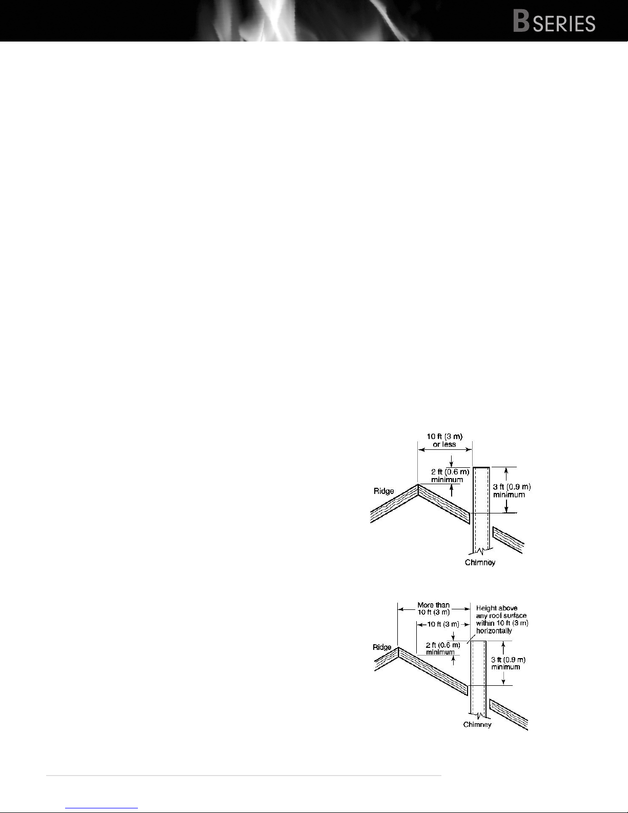
The basic rule is this: the top of the chimney must clear the
roof penetration point (the upper edge) by at least 3 feet
and must clear anything within a 10 foot radius by at least 2
feet. This includes the peak of the house, parapet, dormer,
chimney, or spire. See diagram below.
If the chimney terminates beyond 10 feet from the ridge of
the roof it must clear the upper penetration of the roof by
3 feet. Notice that the flue still terminates 2 feet above the
roof at the 10 foot perimeter:
ATTENTION: DO NOT CONNECT THIS UNIT TO A CHIMNEY
FLUE SERVING ANOTHER APPLIANCE
heatmasterss.com 11
 Loading...