

Heatmaster 25 Tc, 85 TC, 35 TC, 120 TC, 45 TC Installation, Operation And Maintenance Instructions
...
664Y6800 • A
INSTALLATION, OPERATION AND
MAINTENANCE INSTRUCTIONS
25 - 35 - 45 - 70 - 85 - 120 TC
HeatMaster
®
EN
FR
NL
ES
IT
DE
PL
RU
INSTALLATION, OPERATION AND
MAINTENANCE INSTRUCTIONS

en
2
Heat Master TC : 6 64Y6800 • A
EN
FR
NL
ES
IT
DE
PL
RU
TABLE OF CONTENTS
GENERAL RECOMMENDATIONS ...................................................................4
USER'S GUIDE ...............................................................................................5
Instructions for the end user ............................................................................................................................................. 5
Periodic checks ....................................................................................................................................................................5
Control panel ....................................................................................................................................................................... 6
Parameter setting ...............................................................................................................................................................7
APPLIANCE DESCRIPTION ..........................................................................10
Burner description ............................................................................................................................................................12
TECHNICAL CHARACTERISTICS .................................................................13
Burner characteristics .......................................................................................................................................................13
Single gas categories (All models)..................................................................................................................................14
Double gas categories (HM 70 / 85 / 120 TC only)........................................................................................................16
Combustion characteristics.............................................................................................................................................18
Electrical characteristics (HM TC equipped with a standard charging pump)........................................................20
Electrical characteristics (HM TC < 70 kw equipped with a high eciency pump) ...............................................22
Electrical characteristics (HM TC ≥ 70 kw equipped with a high eciency pump)................................................24
Dimensions ........................................................................................................................................................................26
Chimney connection characteristics .............................................................................................................................28
Calculation of the ue pressure drop, or of the corresponding length in meters of straight pipes ...................30
Hydraulic characteristics ..................................................................................................................................................32
DHW performance ............................................................................................................................................................34
Maximum operating conditions .....................................................................................................................................34
INSTALLATION ........................................................................................... 35
Package contents .............................................................................................................................................................. 35
How to move the boiler ...................................................................................................................................................36
Safety instructions for the installation .......................................................................................................................... 37
Recommendations for the prevention of corrosion and scaling ..............................................................................39
Tools required for the installation ..................................................................................................................................41
Boiler preparation ............................................................................................................................................................. 41
DHW connection ...............................................................................................................................................................43
Heating connection ..........................................................................................................................................................44
Gas connection ..................................................................................................................................................................46
Conversion to propane (HM 85 / 120 TC).......................................................................................................................47
Gas circuit connection......................................................................................................................................................48

en
3
Heat Master TC : 6 64Y6800 • A
EN
FR
NL
ES
IT
DE
PL
RU
TABLE OF CONTENTS
STARTING UP .............................................................................................49
Safety instructions for starting up .................................................................................................................................49
Tools required for starting up .........................................................................................................................................49
Checks before starting up ...............................................................................................................................................49
Filling the system .............................................................................................................................................................. 50
Starting up the boiler ....................................................................................................................................................... 51
Checking and adjusting the burner ............................................................................................................................... 52
MAINTENANCE ..........................................................................................53
Safety instructions for the boiler maintenance ...........................................................................................................53
Tools required for maintenance .....................................................................................................................................54
Boiler shut down for maintenance .................................................................................................................................54
Periodic boiler maintenance tasks ................................................................................................................................. 55
Removal, check and reinstallation of the burner electrode.......................................................................................56
Removal and reinstallation of the burner .....................................................................................................................57
Cleaning the exchanger ...................................................................................................................................................58
Removing and cleaning the condensate recovery dish .............................................................................................59
Draining the boiler ............................................................................................................................................................60
Restarting after maintenance .........................................................................................................................................61
In case of problem... ..........................................................................................................................................................62
DECLARATION OF CONFORMITY EC ........................................................63
For specific connection diagrams and the list of associated accessories, the MCBA
parameters and the error codes, refer to the System Control manual provided with
this product.

NOTE
This manual contains important information with respect to the installation, the starting up and the
maintenance of the boiler.
This manual must be provided to the user, who will read it carefully and keep it in a safe place.
We accept no liability should any damage result from the failure to comply with theinstructions
contained in this technical manual.
Essential recommendations for safety
• It is prohibited to carry out any modifications to the appliance without the
manufacturer’s prior and written agreement.
• The product must be installed by a qualified engineer, in accordance with
applicable local standards and regulations.
• The installation must comply with the instructions contained in this manual and
with the standards and regulations applicable to installations.
• Failure to comply with the instructions in this manual could result in personal
injury or a risk of environmental pollution.
• The manufacturer declines all liability for any damage caused as a result of
incorrect installation or in the event of the use of appliances or accessories that are
not specified by the manufacturer.
Essential recommendations for the correct operation of the appliance
• In order to ensure that the appliance operates correctly, it is essential to have it
serviced by a certified installer or maintenance contractor every year.
• In case of anomaly, please call your service engineer.
• Faulty parts may only be replaced by genuine factory parts.
en
4
Heat Master TC : 6 64Y6800 • A
EN
FR
NL
ES
IT
DE
PL
RU
GENERAL RECOMMENDATIONS
If you smell gas:
- Immediately isolate the gas supply.
- Open windows and doors to ventilate the area.
- Do not use any electrical appliances and do not operate any switches.
- Immediately notify your gas supplier and/or your installer.
en
5
Heat Master TC : 6 64Y6800 • A
EN
FR
NL
ES
IT
DE
PL
RU
USER'S GUIDE
INSTRUCTIONS FOR THE END USER
Essential recommendations for safety
• Do not store any flammable or corrosive products, paint, solvents, salts, chloride
products and other detergent products near the appliance.
• This appliance is not intended for use by persons (including children) with reduced
physical, sensory or mental capabilities, or lack of experience and knowledge,
unless supervised or unless they have been given instruction concerning the use
of the appliance by a person responsible for their safety.
PERIODIC CHECKS
Essential recommendations for the correct operation of the appliance
• Make sure that the system water pressure is at least 1 bar when cold.
• If it is required to top up the system to maintain the minimum recommended water
pressure, only add small amounts of water at a time. If a large amount of cold water
is added in a hot boiler, the boiler can be damaged definitively.
• If the system needs to be refilled repeatedly with water, please contact your
installer.
• Regularly check that there is no water on the floor in front of the boiler. If there is,
please call your service engineer.
General remark
• Checking the boiler settings can only be carried out by an ACV-trained installer or
by ACV's maintenance department.

bar
2
1O3
4
2
5
4
1
3
en
6
Heat Master TC : 6 64Y6800 • A
EN
FR
NL
ES
IT
DE
PL
RU
USER'S GUIDE
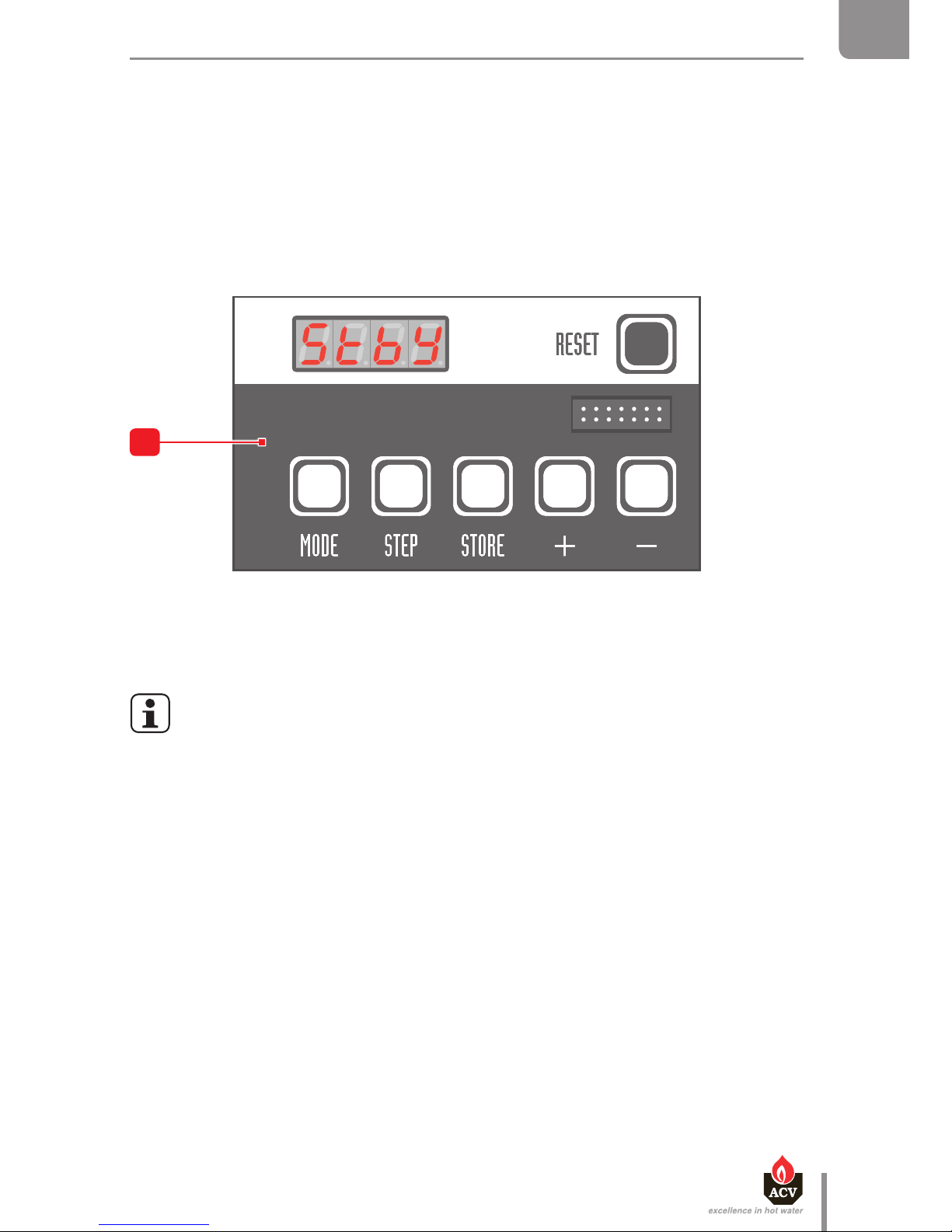
CONTROL PANEL
When the boiler is powered on, it starts in Stand-by mode and displays for 2
seconds before displaying the boiler status.
Description
1. ON/OFF master switch of the boiler - The built-in indicator lights when the appliance is turned on.
2. Summer-winter switch - To activate or deactivate the heating pump. The built-in indicator
lights in winter mode.
3. Pressure gauge - Indicates the primary circuit pressure (min. 1 bar when cold).
4. Pre-cut area - To install an optional Control Unit.
5. User interface of the MCBA controller - Allows to set-up the boiler operation and more
specically, to dene the required temperature of the Domestic Hot Water (DHW) and the Central
Heating (CH) and to activate/deactivate the DHW and heating modes:
• Display : indicates the parameter values, the error codes and the set-up status of
the parameters.
• "Reset" key : to bring the parameters back to the factory-preset values.
• "Mode" key : to toggle the modes and dene various parameters.
• "Step" key : to scroll through the various functions of a mode.
• "Store" key : to save the dened settings.
• "+" key : to increase the displayed value.
• "–" key : to decrease the displayed value.
bar
2
1
O
3
4
5
en
7
Heat Master TC : 6 64Y6800 • A
EN
FR
NL
ES
IT
DE
PL
RU
USER'S GUIDE
To get additional information on how to use the MCBA and the installer-specic settings, refer to the
boiler System Control manual.
General remarks
• The end user is allowed to carry out the set-up mentioned in the following pages.
Any other setup must be carried out by an approved installer.
• If a fault occurs, the MCBA disables the appliance and displays an error code: the
display flashes and the first character is "E" followed by the fault number.
- Reset the appliance by pressing the "RESET" key of the MCBA interface.
- If the error code shows again, contact your installer.
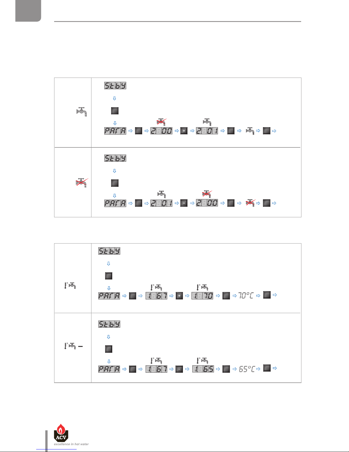
PARAMETER SETTING
The end user is allowed to perform some of the settings: turn on/o the domestic hot water (DHW-)/
heating function and dene the required temperature of the DHW/heating circuits.
Using a special maintenance code to be entered in the MCBA interface, the qualied installers can
access parameters and therefore adjust the boiler settings to specic requirements. The parameters
are normally factory-preset for all normal applications.
en
8
Heat Master TC : 6 64Y6800 • A
EN
FR
NL
ES
IT
DE
PL
RU
USER'S GUIDE
→ Setting the required DHW temperature
DHW mode: When it is enabled through the MCBA, this mode allows to dene the DHW temperature
set-point of the hot water preparation tank. The maximum authorized DHW temperature is 75°C.
→ Enable / disable the DHW mode
2 X
1 X
Mode
Step
X
Mode
Store
1 X
1 X
Stand
by
mode
Stand by mode
ON
2 X
1 X
Mode
Step
2 X
Mode
Store
Stand
by
mode
OFF
2
Stand by mode
1
X
1
X
Mode
Step
2
X
Mode
Store
1
X
Stand
by
mode
1
X
1
X
Mode
Step
2
X
Mode
Store
1
X
Stand
by
mode
+
Stand by mode
Stand by mode

en
9
Heat Master TC : 6 64Y6800 • A
EN
FR
NL
ES
IT
DE
PL
RU
USER'S GUIDE
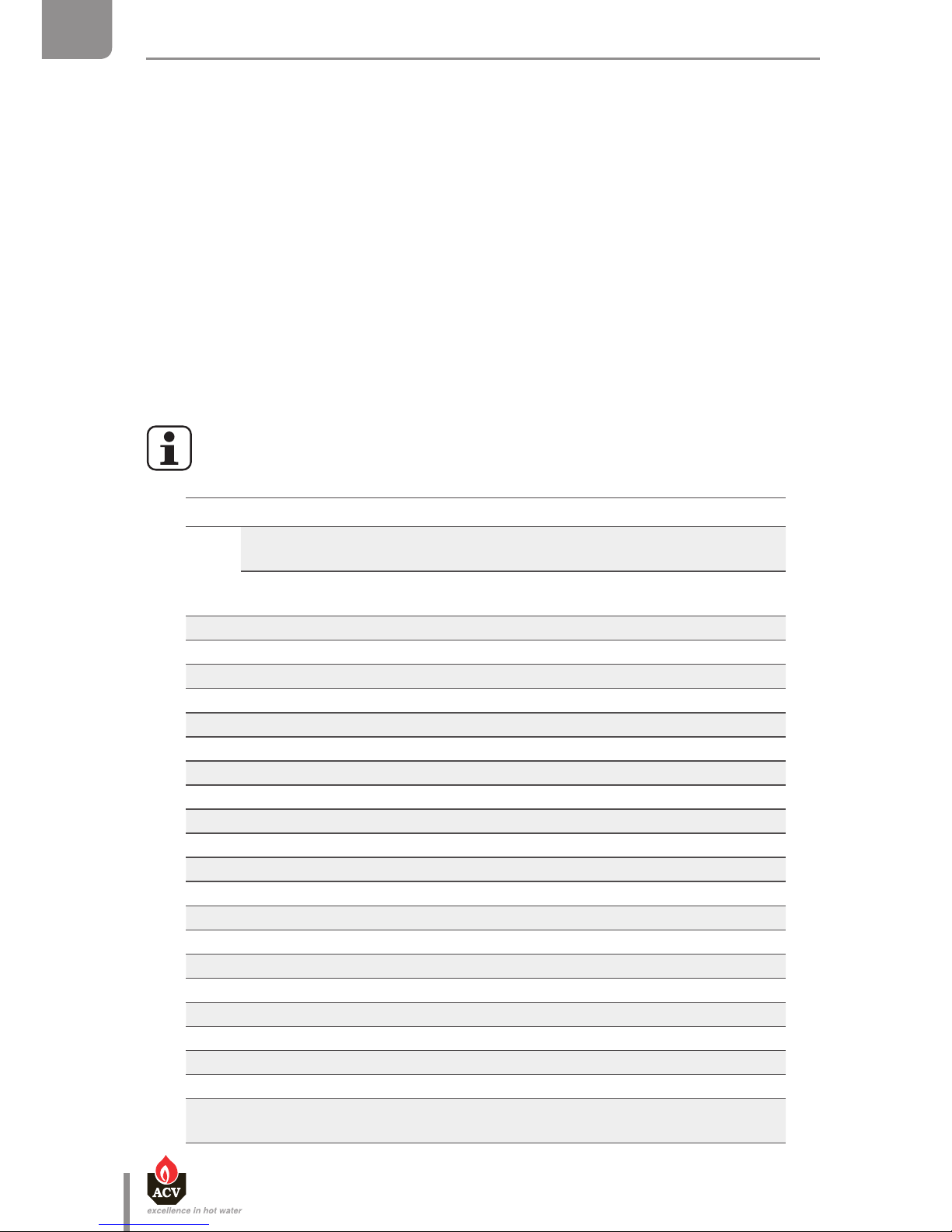
→ Setting the required heating temperature
Central Heating Mode: When it is enabled through the MCBA, this mode allows to dene the
primary circuit temperature set-point for the heating function. The maximum authorized temperature
for the circuit is 90°C.
→ Enable / disable the central heating mode
3 X
1 X
Mode
Step
2 X
Mode
Store
1 X
Stand
by
mode
3 X
1 X
Mode
Step
2 X
Mode
Store
1 X
Stand
by
mode
ON
OFF
Stand by mode
Stand by mode
4
X
1
X
Mode
Step
2
X
Mode
Store
1
X
Stand
by
mode
4
X
1
X
Mode
Step
2
X
Mode
Store
1
X
Stand
by
mode
+
Stand by mode
Stand by mode
en
10
Heat Master TC : 6 64Y6800 • A
EN
FR
NL
ES
IT
DE
PL
RU
APPLIANCE DESCRIPTION
The HeatMaster® TC series combines ACV's "Tank-in-Tank" concept with a double primary circuit to
reach the high performance of a TOTAL CONDENSATION, double-circuit boiler.
The HeatMaster® models are always delivered with an ACV air/gas premix BG 2000-M burner, with low
NOx emissions. During operation, the burner starts automatically as soon as the boiler temperature
gets lower than the preset temperature and stops as soon as the preset temperature is reached.
The appliance is tted with a built-in low water pressure switch that blocks the appliance when the
pressure is not sucient: the heating circuit must be kept under water pressure (at least 1 bar). If the
pressure reading on the pressure gauge is below 0.5 bar, the pressure switch stops the boiler until the
pressure is higher than 0.8 bar again.
The HeatMaster® TC series is tted with a built-in frost protection: as soon as the boiler temperature
[NTC1 sensor] drops below 7°C, the central heating pump is enabled. As soon as the NTC1 temperature
is lower than 3°C, the burner ignites until the temperature exceeds 10°C. The heating pump continues
to run for 10 minutes.
If an outdoor temperature sensor is connected, the pump is started whenever the outdoor temperature
drops below the preset temperature. To allow the boiler to protect the system against frost, all the
radiator and convector valves should be fully open.
Depending on the model, the HeatMaster® TC are equipped with a high efficiency
charging pump, or with a standard charging pump.
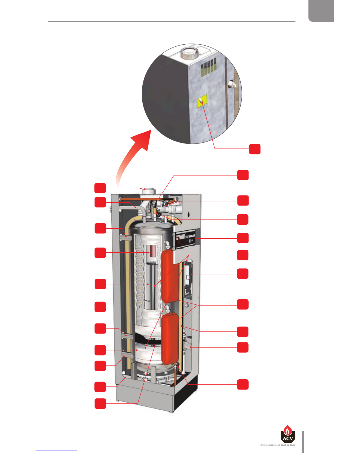
Detail of components
1.
80/125 mm concentric flue pipe connection, that can be transformed into
two 80/80 mm pipes (HM 25 / 35 / 45 TC)
100/150 mm concentric flue pipe connection, that can be transformed into
two 100/100 mm pipes (HM 85/ 120 TC)
2. Domestic hot water outlet
3. Heating circuit outlet
4. Combustion chamber
5. Stainless steel heat exchanger
6. Stainless steel "Tank in Tank" hot water production tank
7. Auxiliary heating circulation loop
8. Indirect water pre-heater
9. Heating circuit inlet
10. Cold water inlet
11. Primary circuit separation disc
12. Gas connection tube
13. Modulating AIR/GAS premix burner
14. Air bleed valve
15. Control panel
16. Heating circuit
17. Electronic board
18. Primary circuit expansion vessel(s) (HM 70 / 85 / 120 TC)
19. Hard expanded polyurethane foam insulation
20. Boiler charging pump (auxiliary circulation loop)
21a. Safety valve (3 bar) (HM TC equipped with a standard pump)
21b Connection + safety valve (3bar) to be installed (HM TC equipped with a
high efficiency pump)
21b
12
13
14
15
16
17
18
19
20
21a
11
10
9
8
7
6
5
4
3
2
1
en
11
Heat Master TC : 6 64Y6800 • A
EN
FR
NL
ES
IT
DE
PL
RU
APPLIANCE DESCRIPTION

en
12
Heat Master TC : 6 64Y6800 • A
EN
FR
NL
ES
IT
DE
PL
RU
APPLIANCE DESCRIPTION
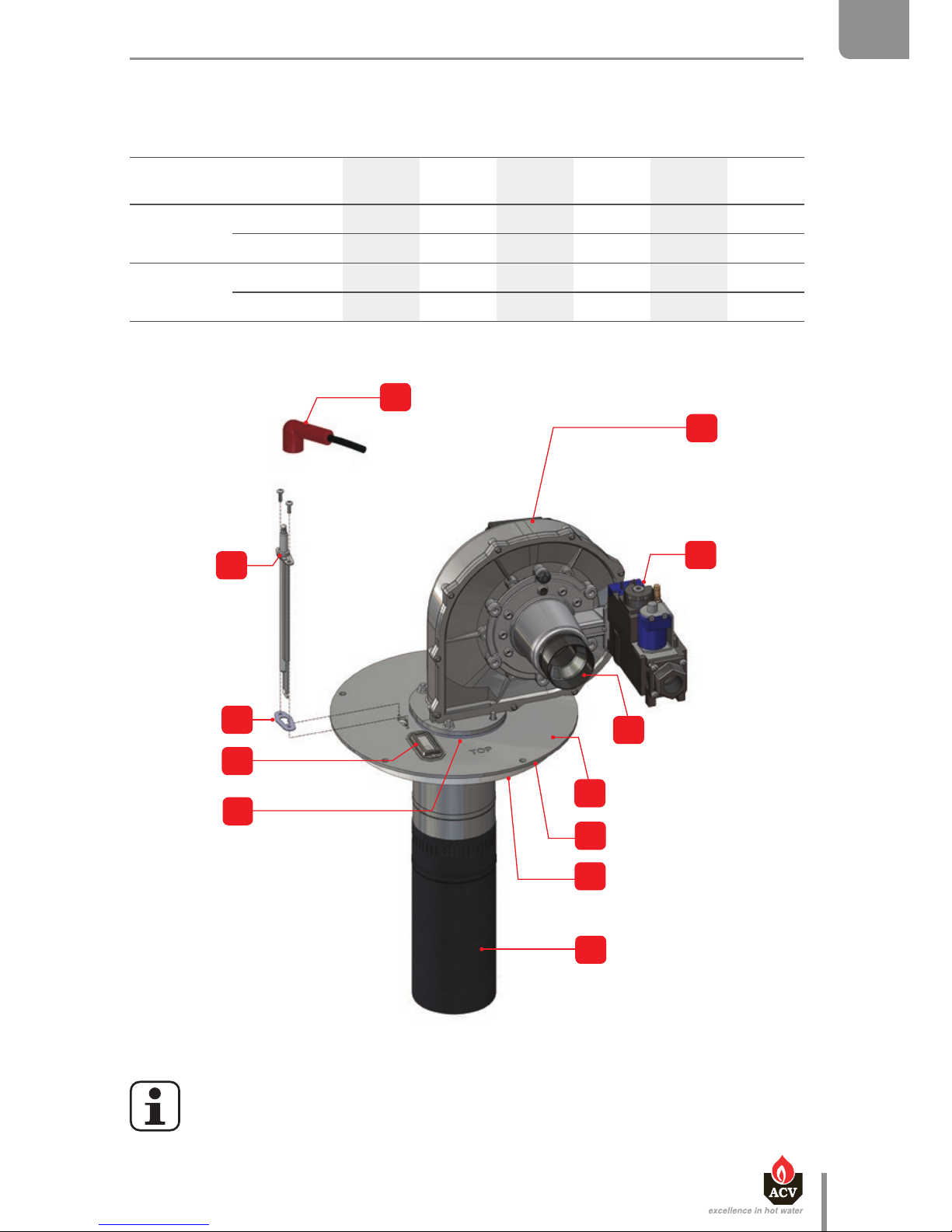
BURNER DESCRIPTION
ACV AIR/GAS premix BG 2000-M burner
Main components of the burner:
- Variable speed fan
- Automatic ignition and ame detection system
- Gas valve/venturi set specially developed for low NOX air/gas premix burners.
The power continually adjusts to demand, which greatly improves the general eciency of the heating
and DHW systems. The burner tube is covered with a metal ber element (NIT) which, besides its
remarkable heat exchange capacity, guarantees longer burner life.
The controller guarantees that the gas pressure at the gas valve outlet is kept equal to the absolute air
pressure at the venturi inlet, corrected by the oset adjustment value. The fan draws the combustion
air through the venturi, whose neck is connected to the gas valve outlet. The pressure dierential
created at the venturi neck by the air ow rate generates a gas intake proportional to its amount (the
higher the air ow rate, the higher the pressure dierential, and therefore the gas intake). The air/gas
mix is then introduced into the burner via the fan.
Detail of components
1.
Fan
2.
Gas valve
3.
Venturi
4.
Burner chamber plate flange
5.
Heat exchanger seal
6.
Insulation
7.
Burner tube
8.
Fan seal
9.
Flame sight glass
10.
Electrode seal
11.
Electrode
12.
Ignition cable (part of the electrode assembly in the HM 45 TC)
12
1
2
3
4
5
6
7
8
10
11
9
en
13
Heat Master TC : 6 64Y6800 • A
EN
FR
NL
ES
IT
DE
PL
RU
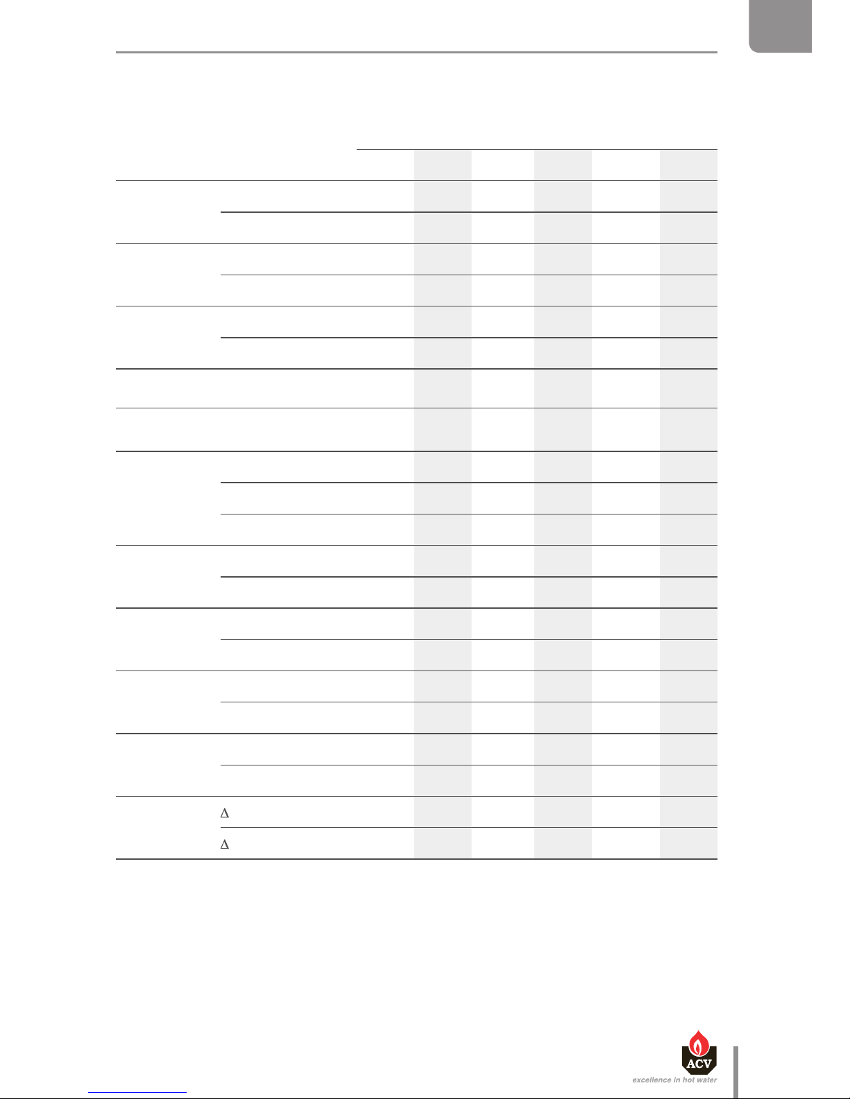
TECHNICAL CHARACTERISTICS
BURNER CHARACTERISTICS
HM 25 TC HM 35 TC HM 45 TC HM 70 TC HM 85 TC HM 120 TC
Gas type
Nat. gas
Propane
Nat. gas
Propane
Nat. gas
Propane
Nat. gas
Propane
Nat. gas
Propane
Nat. gas
Propane
Min fan speed
Nat. gas rpm 1500 2000 1600 1900 1900 1300
Propane rpm 1500 2400 1800 1900 1900 1300
Max. fan speed
Nat. gas rpm 6500 6300 6800 4900 6500 5300
Propane rpm 6100 6500 6900 4500 6000 5300
• The figure shows the HM 120 TC burner. The HM 25 / 35 / 45 / 70 / 85 TC burner
configuration is slightly different.

en
14
Heat Master TC : 6 64Y6800 • A
EN
FR
NL
ES
IT
DE
PL
RU
TECHNICAL CHARACTERISTICS
SINGLE GAS CATEGORIES All models
Gas type G20 G25 G20 / G25 G25.1 G31 G30
Pressure (mbar) 20 25 20-25 25 30 37 50 30 50
Country
code
Category
AT
I
2H
I
3P
I
3B/P
BE
I
2E(S)
*
I
2E(R)
**
I
3P
CH
I
2H
I
3P
I
3B/P
CY
I
2H
I
3B/P
CZ
I
2H
I
3P
DE
I
2E
I
2ELL
I
3P
I
3B/P
DK
I
2H
I
3B/P
EE
I
2H
I
3B/P
ES
I
2H
I
3P
FR
I
2Er
I
3P
I
3B/P
GB
I
2H
I
3P
I
3B/P
GR
I
2H
I
3P
HR
I
2H
I
3P
I
3B/P
HU
I2
HS
I
3B/P
* HM 25 / 35 / 45 / 70 TC
** HM 85 / 120 TC

en
15
Heat Master TC : 6 64Y6800 • A
EN
FR
NL
ES
IT
DE
PL
RU
TECHNICAL CHARACTERISTICS
Gas type G20 G25 G20 / G25 G25.1 G31 G30
Pressure (mbar) 20 25 20-25 25 30 37 50 30 50
Country
code
Category
IE
I
2H
I
3P
IT
I
2H
I
3P
I
3B/P
LT
I
2H
I
3P
I
3B/P
LU
I
2E
I
3B/P
LV
I
2H
NL
I
2L
I
3P
I
3B/P
NO
I
2H
I
3B/P
PL
I
2E
I
3P
I
3B/P
PT
I
2H
I
3P
RO
I
2H
I
2E
I
3P
I
3B/P
SE
I
2H
I
3B/P
SI
I
2H
I
3P
I
3B/P
SK
I
2H
I
3P
I
3B/P
TR
I
2H
I
3B/P

en
16
Heat Master TC : 6 64Y6800 • A
EN
FR
NL
ES
IT
DE
PL
RU
TECHNICAL CHARACTERISTICS
DOUBLE GAS CATEGORIES HM 70 / 85 / 120 TC only
Gas type G20 G25
G20
G25
G31 G30
G30 G31
Pressure (mbar) 20 20 25
20
25
30 37 50 30 50
28 - 30
37
50
67
Country code Category
AT
II
2H3P
II
2H3B/P
CH
II
2H3P
II
2H3B/P
II
2H3+
CY
II
2H3B/P
II
2H3+
CZ
II
2H3P
II
2H3+
DE
II
2E3B/P
II
2ELL3B/P
DK
II
2H3B/P
EE
II
2H3B/P
ES
II
2H3P
FI
II
2H3B/P
FR
II
2Er3P
II
2E+3+
GB
II
2H3P
II
2H3+
GR
II
2H3P
II
2H3+
HR
II
2H3P
II
2H3B/P
HU
II
2H3B/P
IE
II
2H3P
II
2H3+
IT
II
2H3P
II
2H3B/P
II
2H3+

en
17
Heat Master TC : 6 64Y6800 • A
EN
FR
NL
ES
IT
DE
PL
RU
TECHNICAL CHARACTERISTICS
Gas type G20 G25
G20
G25
G31 G30
G30 G31
Pressure (mbar) 20 20 25
20
25
30 37 50 30 50
28 - 30
37
50
67
Country code Category
LT
II
2H3P
II
2H3B/P
II
2H3+
LU
II
2E3B/P
NL
II
2H3B/P
NO
II
2H3B/P
PL
II
2E3B/P
PT
II
2H3P
II
2H3+
RO
II
2H3P
II
2H3B/P
II
2E3B/P
SE
II
2H3B/P
SI
II
2H3P
II
2H3B/P
II
2H3+
SK
II
2H3P
II
2H3B/P
II
2H3+
TR
II
2H3B/P

en
18
Heat Master TC : 6 64Y6800 • A
EN
FR
NL
ES
IT
DE
PL
RU
TECHNICAL CHARACTERISTICS
COMBUSTION CHARACTERISTICS
Main Characteristics
HM 25 TC HM 35 TC HM 45 TC
G20/G25 G31 G20/G25 G31 G20/G25 G31
Input (PCI)
max kW 25.0 25.0 34.9/34.5 31.0 45.6 40.7
min kW 4.7 5 9.8/10.6 10.0 9.0/9.6 8.8
Output at 100%
(80/60°C) kW 24.3 24.3 34.0/33.6 30,2 44.7 39.9
(50/30°C) kW — — — — 47.4 42,3
Eciency at 100%
(80/60°C) % 97.3 97.3 97.3 97.3 98.0 98.0
(50/30°C) % — — — — 103.9 103.9
Eciency at 30% load (EN677) % 108.9 108.9 108.9 108.9 108.9 108.9
Combustion
eciency
at 100% % 98.2 98.2 98.2 98.2 97.9 98.2
NOx (Class 5)
Max. output mg/kWh 74 81 59 72 42 42
Min. output mg/kWh 33 31 33 31 24 24
Weighted mg/kWh 53 53 41 41 38 38
CO
Max. output mg/kWh 44 55,3 89.1/103.9 119.6 61.3/82.2 184
Min. output mg/kWh 23 9 4.6/17.1 20.9 5.9 4.8
CO
2
Max. output %CO29.3 10.7 9.3 10.5 8.9/9.16 11.2
Min. output %CO
2
8.8 10.7 8.4/9.1 9.8 8.7 9.5
Max gas ow rate
G20/G25
20 mbar m³/h 2.64 3.75 4.8
25 mbar m³/h 2.64 4.25 5.7
Max. gas ow rate
G31
30/37/50 mbar Kg/h 2.0 2.0 2.7
30/37/50 mbar m³/h 1.26 1.26 1.66
Standby loss
T = 45 K
W 187 187 187 187 187 187
T = 30 K
W 113 113 113 113 113 113
en
19
Heat Master TC : 6 64Y6800 • A
EN
FR
NL
ES
IT
DE
PL
RU
TECHNICAL CHARACTERISTICS
Main Characteristics
HM 70 TC HM 85 TC HM 120 TC
G20/G25 G31 G20/G25 G31 G20/G25 G31
Input (PCI)
max. kW 69.9 69.9 85.9/85.0 83.6 115/114.6 115
min. kW 24.5 24.5 24.5 24.5 23.2 24.8
Output at 100%
(80/60°C) kW 68.0 68.0 82,.9 83.6 111.6 111.6
(50/30°C) kW — — — — 121.7 121.7
Eciency at 100%
(80/60°C) % 97.3 97.3 97.5 97.5 97.1 97.1
(50/30°C) % — — — — 105.8 105.8
Eciency at 30% load (EN677) % 109.0 109.0 108.4 108.4 108.8 108.8
Combustion
eciency
at 100% % 98.1 98.1 98.0 98.0 97.5 97.5
NOx (Class 5)
Max. output mg/kWh 52 85 72/65 85 57/56 49
Min. output mg/kWh 27 27 27 27 10 42
Weighted mg/kWh 28 28 44 44 56 56
CO
Max. output mg/kWh 56.3 90.0 74.4/118.7 98.8 119.2/121.4 103.0
Min. output mg/kWh 2.0 45.0 5.9/55.0 53.8 7.6/61.8 12.8
CO
2
Max. output %CO29.1 10.9 9.3 10.9 9.3 10.2
Min. output %CO
2
8.6 10.0 8.6 8.5/10.0 8.4 10.0
Max gas ow rate
G20/G25
20 mbar m³/h 7.4 9.0 12.2
25 mbar m³/h 8.6 10.5 14.2
Max. gas ow rate
G31
30/37/50 mbar Kg/h 5.43 5.6 7.5
30/37/50 mbar m³/h 2.86 3.4 4.69
Standby loss
T = 45 K
W 342 342 342 342 342 342
T = 30 K
W 206 206 206 206 206 206
en
20
Heat Master TC : 6 64Y6800 • A
EN
FR
NL
ES
IT
DE
PL
RU
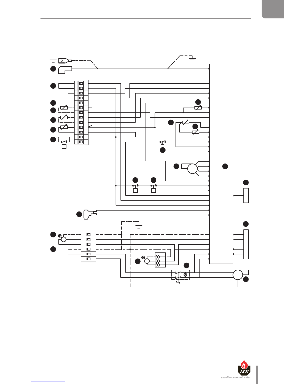
ELECTRICAL CHARACTERISTICS HM TC EQUIPPED WITH A
STANDARD CHARGING PUMP
TECHNICAL CHARACTERISTICS
Description
1. 230 V power supply plug
2. ON/OFF master switch
3. Charging pump
4. Heating pump (option)
5. Gas valve rectifier
6. 230 Volt-24 Volt transformer
7. MCB A
8. Display
9. Low water pressure switch
10. Burner PWM plug
11. Summer/winter switch
12. NTC1 flow sensor
13. NTC2 return sensor
14. NTC5 flue gas temperature sensor
15. Room thermostat (option)
16. NTC3 DHW sensor
17. NTC4 outdoor temperature sensor (option)
18. NTC6 flow sensor for second heating circuit (option)
19. Positive terminal of the ionization current
20. RAM high limit thermostat (option)
21. Ignition and ionization cable
22. 230 Volt burner power supply (HeatMaster® 70 / 85 TC)
23. Gas pressure switch (HeatMaster® 70 / 85 TC)
The ionization current is measured between terminal 19 and ground.
Main Characteristics
HM 25 / 35 TC HM 70 / 85 TC
Rated voltage V~ 230 230
Rated frequency Hz 50 50
Rated current (fuse) A 6 6
Electrical consumption W 176 220 / 230
Input intensity A 0.8 1
IP Class IP 30 IP 30
Br
B
B
V
W
Y/Gr
B
Br
G
R
V
O
R
W
V
R
Bk
B
Bk
O
Br
R
Br
B
R
Br
Bk
Bk
O
Br
B
R
Bk
230V ~ 50Hz
Br
B
Br
B
B
Br
G
R
V
BkB
RB
B
V
G
O
B
BUS B
BUS A
W
Br
Bk
O
Br
R
Bk
Br
G
R
Br
B
Y/Gr Y/Gr
Y/Gr
B
W
L
N
PE
Y/Gr
B
Br
B
B
B
Y/Gr
X12.
P P
X11.
L1
N
PE
M
M
1 2 3 4 5 6 7 8 9 10 11 12 13
1 2 3 4 5 6
X1.6
X1.5
X1.4
X1.3
X1.2
X7
X10.6
X10.7
X10.1
X10.3
X1.1
X2.12
X2.11
X2.10
X2.9
X2.8
X2.7
X2.6
X2.5
X2.4
X2.3
X2.2
X2.1
X3.6
X3.5
X3.4
X3.3
X3.2
X3.1
X4.3
X4.2
X4.1
X5.4
X5.3
X5.2
X5.1
t
V OG
22
23
21
20
19
18
17
16
15
14
13
12
11
10
9
8
7
6
5
4
3
2
1
B. Blue
Bk. Black
Br. Brown
G. Grey
O. Orange
R. Red
V. Violet
W. White
Y/Gr. Yellow/Green
en
21
Heat Master TC : 6 64Y6800 • A
EN
FR
NL
ES
IT
DE
PL
RU
TECHNICAL CHARACTERISTICS
 Loading...