

Page 1
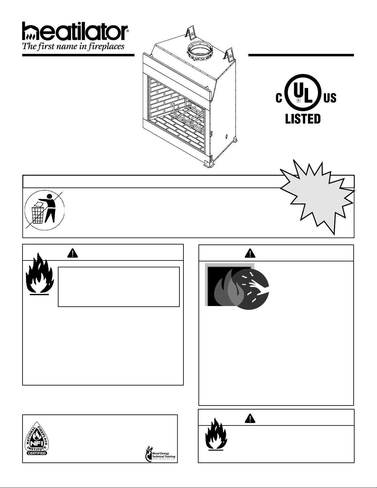
Models:
I80
Woodburning Fireplace
Owner’s Manual
Installation and Operation
CAUTION
DO NOT DISCARD THIS MANUAL
• Important operating
and maintenance
instructions included.
• Read, understand
and follow these
instructions for safe
installation and
operation.
WARNING
If the information in these instructions is not followed exactly, a
fi re may result causing property
damage, personal injury, or death.
• Do not store or use gasoline or other fl am-
mable vapors and liquids in the vicinity of
this or any other appliance.
• Do not overfi re. Overfi ring will void your war-
ranty.
• Comply with all minimum clearances to
combustibles as specifi ed. Failure to
comply may cause house fi re.
DO NOT
DISCARD
• Leave this manual with
party responsible for
use and operation.
WARNING
HOT SURFACES!
Glass and other surfaces are
hot during operation AND
cool down.
Hot glass will cause burns.
• Do not touch glass until it is cooled
• NEVER allow children to touch glass
• Keep children away
• CAREFULLY SUPERVISE children in same room
as fi replace.
• Alert children and adults to hazards of high
temperatures.
High temperatures may ignite clothing or other
fl ammable materials.
• Keep clothing, furniture, draperies and other
fl ammable materials away.
Installation and service of this fi replace should
be performed by qualifi ed personnel. Hearth
& Home Technologies suggests NFI certifi ed
or factory-trained professionals, or technicians
supervised by an NFI certified
professional.
Heatilator • I80 CAN-US • 4013-203 Rev F • 04/08
WARNING
Fire Risk
• For use with solid wood fuel or decorative
gas appliance only.
• Do not install unvented gas logs.
1
Page 2
Read this manual before installing or operating this fi replace.
Please retain this owner’s manual for future reference.
Congratulations!
Congratulations on selecting a Heatilator wood burning fi re-
place. The Heatilator fi replace you have selected is designed
to provide the utmost in safety, reliability and effi ciency.
As the owner of a new fi replace, you’ll want to read and care-
fully follow all of the instructions contained in this owner’s
manual. Pay special attention to all cautions and warnings.
This owner’s manual should be retained for future reference.
We suggest you keep it with your other important documents
and product manuals.
The information contained in this owner’s manual unless noted
otherwise, applies to all models and gas control systems.
Your new Heatilator wood burning fi replace will give you years
of durable use and trouble-free enjoyment. Welcome to the
Heatilator family of fi replace products!
Homeowner Reference Information
We recommend that you record the following pertinent
information about your fi replace:
Model Name: Date purchased/installed:
Serial Number: Location on fi replace:
Dealership purchased from: Dealer phone:
Notes:
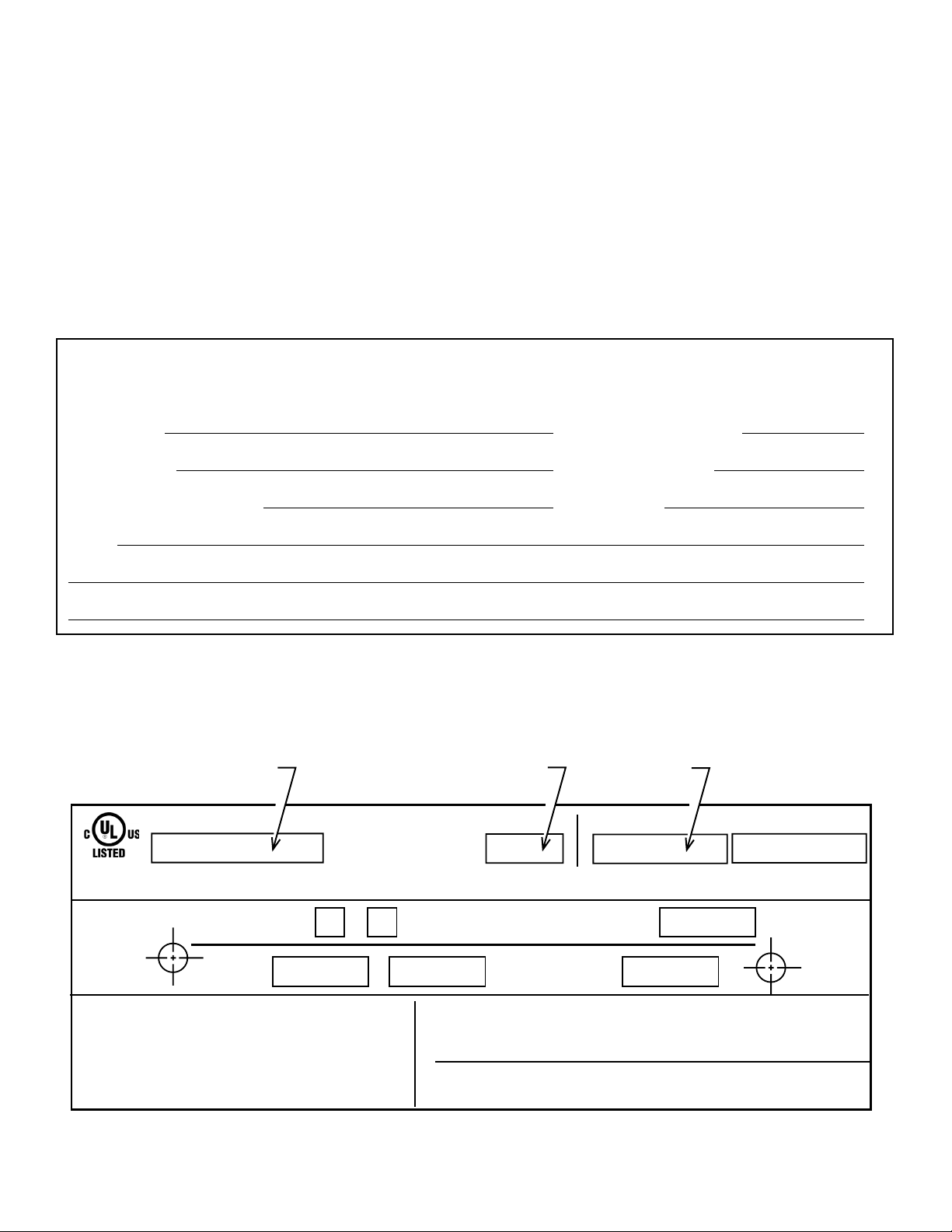
Listing Label Information/Location
The model information regarding your specifi c fi replace can be found on the rating plate located on the smoke shield of the
fi replace.
Serial
Number
Grate
Fireplace
Model
FIREPLACE NO.
FIRECHAMBER INTENDED FOR USE WITH HEARTH & HOME TECHNOLOGIES INC. LISTED FIREPLACE PARTS. SEE INSTALLATION AND
OPERATING INSTRUCTIONS FOR THIS MODEL. ONLY HEARTH & HOME TECHNOLOGIES INC. GLASS DOOR KITS CAN BE INSTALLED ON THIS UNIT.
FIREPLACE ALSO FOR USE
IN MANUFACTURED HOMES
FAN KI T
MODEL NO.
DO NOT OVERFIRE. USE ONLY: SOLID WOOD FUEL OR
LISTED DECORATIVE GAS APPLIANCE. DO NOT USE A
FIREPLACE INSERT OR OTHER PRODUCTS NOT
SPECIFIED FOR USE WITH THIS PRODUCT. IF DOORS
ARE USED OPERATE FIREPLACE WITH DOORS FULLY
OPEN OR CLOSED ONLY. WHEN BURNING A
DECORATIVE GAS APPLIANCE IN THE FIREPLACE,
ADJUST DAMPER TO THE FULLY OPEN POSITION.
2
YES
WARNING: RISK OF
FIRE DAMAGE. REPLACE
GRATE WITH HEARTH & HOME
TECHNOLOGIES INC.
NO
&
Heatilator • I80 CAN-US • 4013-203 Rev F • 04/08
MODEL NO.
CLEARANCE TO
COMBUSTIBLES:
WARNING! THIS FIREPLACE HAS NOT BEEN TESTED WITH AN UNVENTED
GAS LOG SET. TO REDUCE THE RISK OF FIRE OR INJURY, DO NOT
INSTALL AN UNVENTED GAS LOG SET INTO FIREPLACE.
WARNING! THIS APPLIANCE IS NOT FOR USE AS COOKING EQUIPMENT.
IF INSTALLATION OR OPERATING INSTRUCTIONS ARE MISSING
CONTACT: HEARTH & HOME TECHNOLOGIES INC.,
1915 W. SAUNDERS ST., MT. PLEASANT, IA 52641.
CHIMNEY
2 IN. MIN.
RATED AT
115 VOLTS, 50/60 Hz.,
MODEL NO.
FIREBOX
MFG. DATE
IN.
MIN.
AMP.
Page 3

Table of Contents
1 Listing and Code Approvals 4
A. Appliance Certifi cation . . . . . . . . . . . . . . . . . . . . . . . . . 4
2 Getting Started 5
A. Design and Installation Considerations . . . . . . . . . . . . 5
B. Negative Pressure . . . . . . . . . . . . . . . . . . . . . . . . . . . .5
C. Typical Fireplace System . . . . . . . . . . . . . . . . . . . . . . . 7
D. Tools and Supplies Needed . . . . . . . . . . . . . . . . . . . . . 8
E. Inspect Fireplace and Components . . . . . . . . . . . . . . . 8
3 Framing and Clearances 9
A. Selecting Fireplace Location . . . . . . . . . . . . . . . . . . . . 9
B. Clearances . . . . . . . . . . . . . . . . . . . . . . . . . . . . . . . . . 10
C. Sidewalls/Surrounds . . . . . . . . . . . . . . . . . . . . . . . . . 11
D. Frame the Fireplace . . . . . . . . . . . . . . . . . . . . . . . . . . 11
E. Construct the Chase . . . . . . . . . . . . . . . . . . . . . . . . . 12
F. Chimney Requirements . . . . . . . . . . . . . . . . . . . . . . . 12
4 Installation of Fireplace 13
A. Install the Outside Air Kit . . . . . . . . . . . . . . . . . . . . . . 13
B. Secure the Fireplace . . . . . . . . . . . . . . . . . . . . . . . . . 15
C. Install the Refractory . . . . . . . . . . . . . . . . . . . . . . . . . 15
D. Place the Protective Metal Hearth Strips . . . . . . . . . .18
E. Level the Fireplace. . . . . . . . . . . . . . . . . . . . . . . . . . . 18
5 Chimney Assembly 19
A. Chimney Requirements . . . . . . . . . . . . . . . . . . . . . . .20
B. Using Offsets/Returns . . . . . . . . . . . . . . . . . . . . . . . . 21
C. Assemble the Chimney Sections . . . . . . . . . . . . . . . .22
D. Install the Ceiling Firestops . . . . . . . . . . . . . . . . . . . . 22
E. Install the Attic Insulation Shield . . . . . . . . . . . . . . . . 23
F. Double-check the Chimney Assembly . . . . . . . . . . . .24
G. Secure the Chimney . . . . . . . . . . . . . . . . . . . . . . . . .24
6 Complete the Enclosure 25
A. Chimney Termination . . . . . . . . . . . . . . . . . . . . . . . . .25
B. Chase Top . . . . . . . . . . . . . . . . . . . . . . . . . . . . . . . . . 27
C. Install the Termination Cap . . . . . . . . . . . . . . . . . . . . 27
7 Accessories 29
A. Gas Log/Lighter Provisions . . . . . . . . . . . . . . . . . . . . 29
8 Finishing 30
A. Hearth Extension . . . . . . . . . . . . . . . . . . . . . . . . . . . .30
B. Finishing Material . . . . . . . . . . . . . . . . . . . . . . . . . . . . 32
C. Mantel . . . . . . . . . . . . . . . . . . . . . . . . . . . . . . . . . . . .33
D. Sidewalls/Surrounds . . . . . . . . . . . . . . . . . . . . . . . . .33
E. Glass Doors . . . . . . . . . . . . . . . . . . . . . . . . . . . . . . . . 33
9 Operating Instructions 34
A. General Information . . . . . . . . . . . . . . . . . . . . . . . . . . 34
B. Outside Air . . . . . . . . . . . . . . . . . . . . . . . . . . . . . . . . . 35
C. Clear Space Near the Fireplace. . . . . . . . . . . . . . . . . 35
D. Flue Damper . . . . . . . . . . . . . . . . . . . . . . . . . . . . . . .35
E. Firescreen . . . . . . . . . . . . . . . . . . . . . . . . . . . . . . . . . 35
F. Glass Doors . . . . . . . . . . . . . . . . . . . . . . . . . . . . . . . . 35
G. Grate . . . . . . . . . . . . . . . . . . . . . . . . . . . . . . . . . . . . . 36
H. Wood Fuel . . . . . . . . . . . . . . . . . . . . . . . . . . . . . . . . . 36
I. Starting a Fire . . . . . . . . . . . . . . . . . . . . . . . . . . . . . . 37
10 Troubleshooting 38
A. Understanding Vent Problems . . . . . . . . . . . . . . . . . . 38
B. Diagnostics and Problem Solving . . . . . . . . . . . . . . . 39
11 Maintenance and Servicing the Fireplace 41
A. Disposal of Ashes . . . . . . . . . . . . . . . . . . . . . . . . . . . 41
B. Chimney Inspection/Cleaning . . . . . . . . . . . . . . . . . . 41
C. Firebox Refractory . . . . . . . . . . . . . . . . . . . . . . . . . . . 41
D. Maintenance Task List . . . . . . . . . . . . . . . . . . . . . . . . 42
E. Chimney Fire . . . . . . . . . . . . . . . . . . . . . . . . . . . . . . . 42
12 Reference Materials 43
A. Fireplace Dimensions . . . . . . . . . . . . . . . . . . . . . . . .43
B. Fireplace Components . . . . . . . . . . . . . . . . . . . . . . . . 44
C. Chimney Components . . . . . . . . . . . . . . . . . . . . . . . . 45
D. Service Parts . . . . . . . . . . . . . . . . . . . . . . . . . . . . . . . 50
E. Limited Warranty . . . . . . . . . . . . . . . . . . . . . . . . . . . . 55
F. Contact Information . . . . . . . . . . . . . . . . . . . . . . . . . . 56
Note: An arrow (¨) found in the text signifi es change in content.
Heatilator • I80 CAN-US • 4013-203 Rev F • 04/08
3
Page 4
1
Listing and Code Approvals
1
A. Appliance Certifi cation
This fi replace system has been tested and listed in accor-
dance with UL 127 and ULC-S610 standards by Underwriters Laboratories Inc. for installation and operation in the
United States and Canada.
This fi replace has been tested and listed for use with the op-
tional components specifi ed in this manual. These optional
components may be purchased separately and installed at
a later date. Installation of an outside air kit will require signifi cant reconstruction and is best if installed at the time of
fi replace installation.
Heatilator is a registered trademark of Hearth & Home Technologies Inc.
WARNING
Fire Risk
WARNING
Improper installation, adjustment, alteration, service
or maintenance can cause injury or property damage.
Refer to the owner’s information manual provided with
this fi replace. For assistance or additional information
consult a qualifi ed installer, service agency or your
dealer.
Not intended for use as a primary heat source.
This fi replace is tested and approved as a decorative fi re-
place. It should not be factored as a primary heat source
in residential heating calculations.
• Do not install or operate damaged fi replace.
• Do not modify fi replace.
• Installation other than as instructed by Hearth & Home
Technologies Inc. is strictly prohibited.
• Do not operate the fi replace without fully assembling
all components.
• Do not overfi re.
• Do not install an unvented gas log set. This fi replace
has not been tested for use with unvented gas log
sets.
• Installation and/or use of any component part not
approved by Hearth & Home Technologies.
Hearth & Home Technologies disclaims any responsibility
for, and the warranty and agency listing will be voided by
the above actions.
4
Heatilator • I80 CAN-US • 4013-203 Rev F • 04/08
Page 5
2
Getting Started
2
A. Design and Installation Considerations
CAUTION
Check building codes prior to installation.
• Installation MUST comply with local, regional,
state and national codes and regulations.
• Consult insurance carrier, local building inspector,
fi re offi cials or authorities having jurisdiction about
restrictions, installation inspection and permits.
When planning a fi replace installation, it is necessary to de-
termine the following information before installing:
• Where the fireplace is to be installed. See Sections
3 and 4.
• The vent system confi guration to be used. See Sections
5 and 6.
• Gas supply piping. See Section 7.
• Framing and fi nishing details. See Sections 3, 6 and 8.
• Whether optional accessories—devices such as a fan, wall
switch or remote control —are desired. See Section 12.
Draft is the pressure difference needed to vent fi replaces
successfully. Considerations for successful draft include:
• Preventing negative pressure
• Location of fi replace and chimney
WARNING
Asphyxiation Risk
Negative pressure can cause spillage of
combustion fumes and soot. Fire needs to draft
properly for safe operation.
B. Negative Pressure
Negative pressure results from the imbalance of air available for the fi replace to operate properly. Causes for this
imbalance include:
• Exhaust fans (kitchen, bath, etc.).
• Range hoods.
• Combustion air requirements for furnaces, water heaters
and other combustion appliances.
• Clothes dryers.
• Location of return-air vents to furnace or air
conditioning.
• Imbalances of the HVAC air handling system.
• Upper level air leaks: recessed lighting, attic hatch
opening, duct leaks.
To minimize the effects of negative air pressure, the following must be considered:
• Install the outside air kit. Install the intake on the side of
the house towards prevailing winds during the heating
season.
• Ensure adequate outdoor air is supplied for combustion
appliances and exhaust equipment.
• Ensure furnace and air conditioning return vents are not
located in the immediate vicinity of the fi replace.
• Avoid installing the fi replace near doors, walkways or small
isolated spaces.
• Recessed lighting should be a “sealed can” design; attic
hatches weather stripped or sealed; attic mounted duct
work and air handler joints and seams taped or sealed.
• Basement installations should be avoided due to stack
effect. Stack effect creates negative pressure in lower
levels. Hearth & Home Technologies recommends the
use of direct vent fi replaces in basements.
Heatilator • I80 CAN-US • 4013-203 Rev F • 04/08
5
Page 6
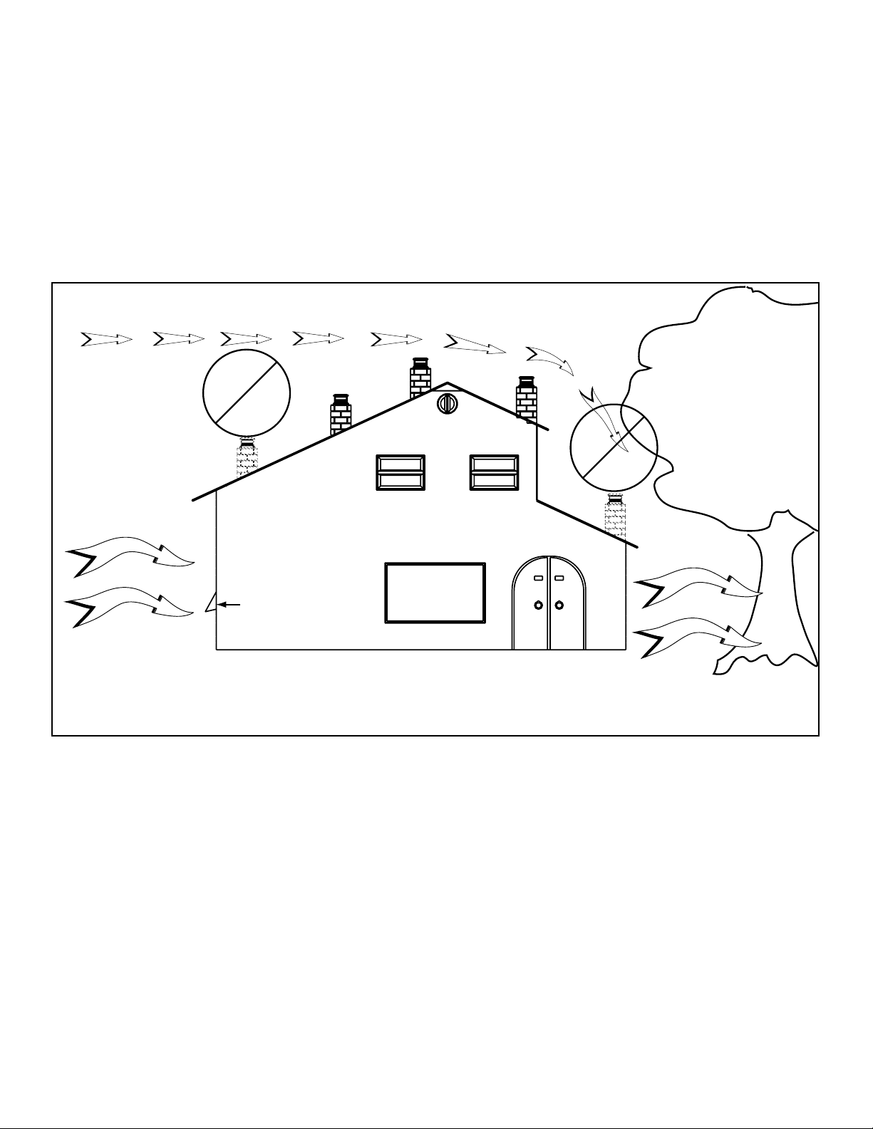
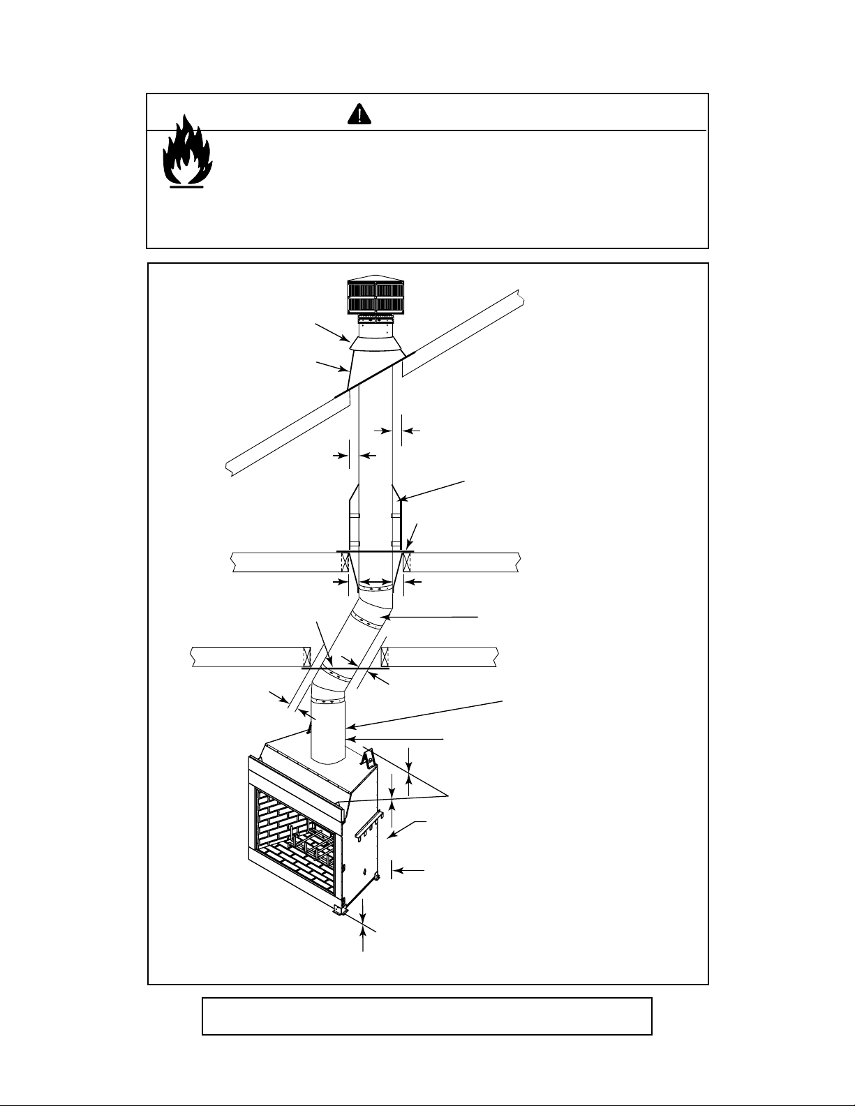
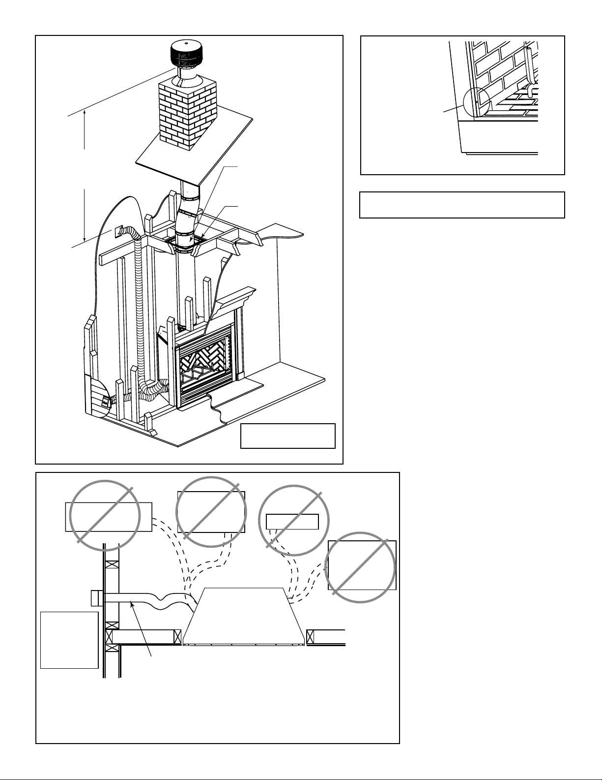
Location of the fi replace and chimney will affect performance.
As shown in Figure 2.1 the chimney should:
• Be installed through the warm airspace enclosed by the
building envelope. This helps to produce more draft,
especially during lighting and die-down of the fi re.
• Penetrate the highest part of the roof. This minimizes the
effects of wind turbulence.
• Be located away from trees, adjacent structures, uneven
roof lines and other obstructions.
Offsets can restrict draft so their use should be minimized.
Consider the fi replace location relative to fl oor and ceiling
and attic joists.
Windward
Location
Not
Recommended
Outside Air Intake
Marginal
Location
Recommended
Location
Multi-level Roofs
Recommended
Location
Location
Not
Recommended
Leeward
Figure 2.1 Recommended Chimney Locations
6
Heatilator • I80 CAN-US • 4013-203 Rev F • 04/08
Page 7
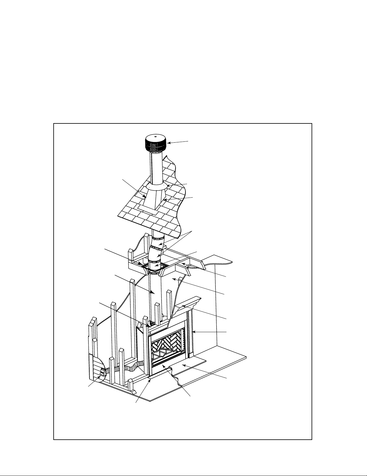
C. Typical Fireplace System
The Heatilator fi replace system consists of the following:
• Fireplace/integral grate/refractory/outside air system
• Refractory
• Chimney termination cap
• Chimney system (SL1100 series pipe is NOT approved for Canada)
• Hearth extension
Optional components include:
• Glass doors
• Chimney air kit (required in Canada)
• SLA10 - 11-10 in./279-254mm adaptor (required in Canada)
Additional lateral
support for chimney
above roof (or enclosed
in chase) if needed
Non-combustible
roof flashing maintains
minimum clearance
around chimney
Support straps
on rafter supports
chimney (not shown)
Ceiling firestop
on floor of attic
Termination cap
Storm Collar
Chimney penetrates roof
preferably without affecting
roof rafters
Offset/Return (with hanger straps)
Attic insulation shield (not shown) must
be used here to keep insulation away
from chimney if attic is insulated
Chimney system
Combustible
framing/header
on top of
V-shaped
standoffs
(spacers)
Outside
combustion air
Protective metal
hearth strip(s)
Figure 2.2 Typical Fireplace System
Framing headed off
in ceiling joists
Enclosed space above
and around fireplace
Mantel and surround
Decorative facing
and trim
Hearth extension
Factory-built fireplace
Heatilator • I80 CAN-US • 4013-203 Rev F • 04/08
7
Page 8
D. Tools and Supplies Needed
E. Inspect Fireplace and Components
Before beginning the installation be sure the following tools
and building supplies are available:
Reciprocating saw Framing material
Pliers High temp caulking material
Hammer Gloves
Phillips screwdriver Framing square
Flat blade screwdriver Electric drill and bits
Plumb line Safety glasses
Level Tape measure
1/2-3/4 in. length, #6 or #8 self-drilling screws
Misc. screws and nails
CAUTION
• Keep fi replace dry.
• Mold or rust may cause odors.
WARNING
Fire Risk
Explosion Risk
Inspect fireplace and components for
damage. Damaged parts may impair safe
operation.
• Do NOT install damaged components.
• Do NOT install incomplete components.
• Do NOT install substitute components
Report damaged parts to dealer.
• Carefully remove the fi replace and components from the
packaging.
• The vent system components and doors are shipped in
separate packages.
• Report to your dealer any parts damaged in shipment.
• Read all the instructions before starting the installation.
Follow these instructions carefully during the
installation to ensure maximum safety and benefi t.
8
Heatilator • I80 CAN-US • 4013-203 Rev F • 04/08
Page 9
3
Framing and Clearances
3
WARNING
Fire Risk
Provide adequate clearances.
• Around air openings
• To combustibles
• For service access.
Locate fi replace away from traffi c areas.
A. Selecting Fireplace Location
Several options are available to you when choosing a location for your fi replace. This fi replace may be used as a room
divider, installed along a wall, across a corner or used in an
exterior chase. See Figure 3.1.
21-1/2 in.
(546 mm)
46-3/8 in.
(1178 mm)
As a room
divider
48 in.
(1219 mm)
min.
65-5/8 in.
(1667 mm)
Across a
corner
51-1/2 in.
1308 mm)
92-3/4 in. (2356 mm)
28-1/2 in.
(724 mm)
A
In an exterior chase
or projecting into a
garage
Along a wall
Note:
• Illustrations and photos refl ect typical installations
and are FOR DESIGN PURPOSES ONLY.
• Illustrations/diagrams are not drawn to scale.
• Actual installation/appearance may vary due to
individual design preference.
• Hearth & Home Technologies reserves the right to
alter its products.
Locating the fi replace in a basement, near frequently opened
doors, central heat outlets or returns, or other locations of
considerable air movement can affect the performance and
cause intermittent smoke spillage from the front of the fi re-
place. Consideration should be given to these factors before
deciding on a location. See Sections 2 and 10.
1-1/2 in. (38 mm) min.
28-1/2 in.
(724 mm)
Note:
distance from sides & back
of fireplace to combustible
materials. 1/2 in. (13 mm)
min. at nailing flanges.
A
24 in.
(610 mm)
min.
24 in.
(610 mm)
min.
A
5/8 in. (16 mm)
all configurations
28-1/2 in. (724 mm)
In addition to these
Note:
framing dimensions,
also reference the
following sections:
• Clearances (Section
3.B.)
• Mantel Projections
(Section 8.C)
• Fireplace Dimensions
(Section 12.A.)
(610 mm)
¨
Figure 3.1 Fireplace Locations
24 in.
min.
Heatilator • I80 CAN-US • 4013-203 Rev F • 04/08
I80 A
With Outside
Air
Without
Outside Air
in. 59-1/2
mm 1511
in. 51-1/2
mm 130 8
9
Page 10
B. Clearances
WARNING
Fire Risk
• Comply with all minimum clearances to combustibles as specifi ed.
• Framing or fi nishing material used on the front of, or in front of, the
appliance closer than the minimums listed, must be constructed entirely
of noncombustible materials (i.e., steel studs, concrete board, etc.).
Failure to comply may cause fi re.
Storm Collar
(roof)
Roof Flashing
2 in. min.
2 in. min.
(51 mm)
(attic)
(51 mm)
Attic
Insulation
Shield
Ceiling Firestop
2 in. min.
Ceiling Firestop
2 in. min.
(51 mm)
(51 mm)
(ceiling)
2 in. min.
(51 mm)
0 in.
from floor
(ceiling)
2 in. min.
(51 mm)
Offset/Return with
hanger straps
Must have 2 in. (51 mm)
minimum clearance
to header
Adaptor attached here (not shown)
0 in. to level
of standoffs
1-1/2 in. (38mm) from
back of appliance
1-1/2 in. (38mm) from
side of appliance
(except at nailing flanges
where it is 1/2 in. (13 mm)
10
Figure 3.2 Clearances to Combustible Materials
Note: Chimney air kit and 11-10 in./279-254mm adaptor are not shown,
but are required in Canada.
Heatilator • I80 CAN-US • 4013-203 Rev F • 04/08
Page 11
C. Sidewalls/Surrounds
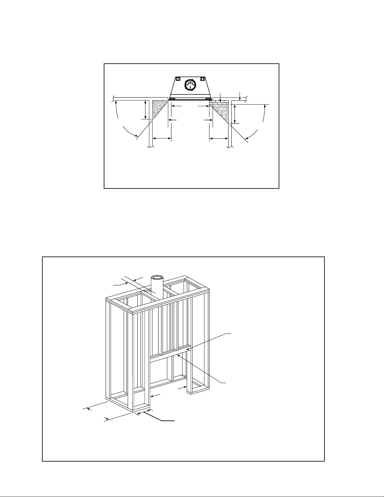
Adjacent combustible side walls must be located a minimum of 24 in. (610 mm) from the fi replace opening. See Figure 3.3.
If you are using a decorative surround constructed of combustible material, it must be located within the shaded area defi ned in Figure 3.3. Short stub walls are also acceptable if they are contained within the shaded area.
4 in.
(102 mm)
19-3/4 in.
(502 mm)
39°
FLUSH FRONT
23 in.
(584 mm)
50°
24 in.
(610 mm)
Figure 3.3 Sidewalls and Surrounds
¨
BRICK
FRONT
42 in.
(1067 mm)
50-1/2 in.
(1283 mm)
24 in.
(610 mm)
D. Frame the Fireplace
Figure 3.4 shows a typical framing (using 2 x 4 lumber) of the fi replace, assuming combustible materials are used. All re-
quired clearances to combustibles around the fi replace must be adhered to. See Figure 3.2. Any framing across the top of
the fi replace must be above the level of the top standoffs.
2 in. (51 mm)
minimum air
space clearance
to the enclosure.
28-1/2 in.
(724 mm)
51-1/2 in.
(1308 mm)
8 in. (203 mm) extra space needed for outside
air connection. If outside air duct has no bend,
this dimension may be reduced as long as
minimum clearances are met.
Note: Fireplace header
cannot be positioned until
after the fireplace
assembly is in place.
Use only noncombustible
material below the top of
the front standoffs.
¨
Figure 3.4 Framing the Fireplace
Heatilator • I80 CAN-US • 4013-203 Rev F • 04/08
11
Page 12
E. Construct the Chase
A chase is a vertical boxlike structure built to enclose the fi re-
place and/or its vent system. Vertical chimneys that run on
the outside of a building must be installed inside a chase.
Construction of the chase may vary with the type of building. These instructions are not substitutes for the requirements of local building codes. Local building codes MUST
be checked.
Chases should be constructed in the manner of all outside
walls of the home to prevent cold air drafting problems. The
chase should not break the outside building envelope in any
manner. All outer walls need to be insulated.
Building codes require false ceiling and ceiling fi restops at
each fl oor of the chase or every 10 ft (3.05 m) of clear space
to control spread of fi re.
Walls, ceiling, base plate and cantilever fl oor at the fi rst level
of the chase should be insulated. See Figure 3.5. Vapor and
air infi ltration barriers should be installed in the chase as per
regional codes for the rest of the home. Additionally, Hearth
& Home Technologies recommends that the inside surfaces be sheet rocked and taped (or the use of an equivalent
method) for maximum air tightness.
Gas line holes and other openings should be caulked with
high temperature caulk or stuffed with unfaced fi berglass in-
sulation. If the fi replace is being installed on a cement slab,
we recommend that in cold climates, a sheet of plywood or
other raised platform be placed underneath to prevent conducting cold up into the room.
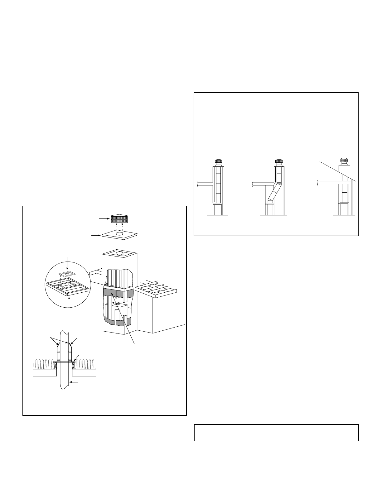
Three examples of chase applications are shown in Figure 3.6.
1. Fireplace and chimney enclosed in an exterior chase.
2. Chimney offset through exterior wall and enclosed in
chase.
3. Chase constructed on roof.
All outside walls should be insulated.
Round Termination Cap
Metal Chase Top
Ceiling
Firestop
False Ceiling
Attic
Tabs
Insulation
False Ceiling
Figure 3.5 Chase Assembly
Insulation
Shield
Ceiling
Firestop
Insulation
False Ceiling
Chimney
Insulation in the
outside walls
of the chase
12 3
Figure 3.6 Chase Constructions
F. Chimney Requirements
When planning your fi replace location, the chimney con-
struction and necessary clearances must be considered.
The fi replace system and chimney components have been
tested to provide fl exibility in construction. Vertical distances
are measured from the base of the fi replace as shown in
Figure 5.2.
ft m
• Minimum overall straight height 18 5.5
• Minimum height with offset/return 18.5 5.6
•Maximum height 90 27.4
• Maximum chimney length between an offset and
return
• Maximum distance between chimney stabilizers 35 10.7
• Double offset/return minimum height 24 7.3
• Maximum unsupported chimney length between the
offset and return
• Maximum straight unsupported chimney height
above the fi replace
• Maximum unsupported chimney above roof 6 1.8
20 6
61.8
35 10.7
12
Note: A maximum of two pairs of offsets and returns may
be used.
Heatilator • I80 CAN-US • 4013-203 Rev F • 04/08
Page 13
4
Installation of Fireplace
4
CAUTION
Sharp Edges
• Wear protective gloves and safety glasses
during installation.
¨
A. Install the Outside Air Kit
The outside air assembly is factory installed on the left side
of the fi replace. The kit is an optional component and its use
is highly recommended to minimize the effect of negative
pressure within the structure.
• Use short duct run.
• A small dip in the duct will create a cold air trap.
• Position the outside air inlet in a manner that will now allow
snow, leaves, etc. to block the inlet. See Figure 4.3.
• You may run the duct vertically; refer to Figure 4.2.
• Locate outside air kit on left side of fireplace. See
Figure 4.1.
• Check the operation of the outside air inlet by moving the
control handle up and down. See Figure 4.4.
• Mark and cut out a 4 in. (102 mm) hole in the building side
for air entry.
• Install the hooded air inlet in the sidewall of the structure,
fl ush with the building’s exterior.
• Assemble the fl exible duct (not supplied) between the
collar and the air inlet. Secure into position with the
supplied wire ties.
• Check for light leaks with a fl ashlight and seal with duct
tape and/or insulation.
WARNING
Fire Risk
Asphyxiation Risk
Do not draw outside combustion air from:
• Wall, fl oor or ceiling cavity.
• Enclosed space such as an attic or
garage.
• Close proximity to exhaust vents or
chimneys.
Fumes or odor may result.
CAUTION
Risk of Smoke Spillage
Outside air inlet must be located to prevent blockage
from:
• Leaves
• Snow/ice
• Other debris
Blockage may cause combustion air starvation.
Flexible Duct
(not supplied)
Outside Air
Shield
Figure 4.1 Outside Air Installation
Heatilator • I80 CAN-US • 4013-203 Rev F • 04/08
2 Wire Ties
Inlet Ring
13
Page 14
3 ft min. from top of
uppermost chimney
section to air inlet.
Attic insulation shield
must be used to keep
insulation away from
chimney.
Handle up - open
Handle down - closed
Figure 4.4 Locating the Outside Air Control
Figure 4.2 Typical Outside Air Inlet Locations
Ceiling firestop
on floor of attic.
11-10 in./279-254mm
adaptor not shown
Note: Chimney air kit and 11-10 in./279-254mm
adaptor are required in Canada.
NO
NO
Outlet blocked by
snow, leaves, etc.
Garage or
combustible
liquids storage
YES
Clear area
outside
house or in
ventilated
crawl space
Use only duct materials specified
by manufacturer (preferably with
short run or mainly straight duct,
except small dip for cold air trap
which will help prevent flow of cold air).
Figure 4.3 Outside Combustion Air Placement
14
Heatilator • I80 CAN-US • 4013-203 Rev F • 04/08
NO
Attic space
NO
Outlet placed
higher than 3 ft
below the
termination cap
Factory-built
fireplace
Page 15
B. Secure the Fireplace
• Position the Fireplace
This fi replace may be placed on either a combustible or
noncombustible continuous fl at surface. Follow the in-
structions for framing in Section 3.D. Slide the fi replace
into position. Be sure to provide the minimum air clearance at the sides and back of the fi replace assembly.
See Section 3.B.
• Remove smoke shield by removing fi ve screws. See
Figure 4.7. Smoke shield is located at top of fi replace
front.
• Remove screens by removing screw from the end of each
screen rod. See Figure 4.8.
Smoke Shield
Front Face
WARNING
Fire Risk!
• Prevent contact with sagging, loose
insulation.
• Do NOT install against vapor barriers or
exposed insulation.
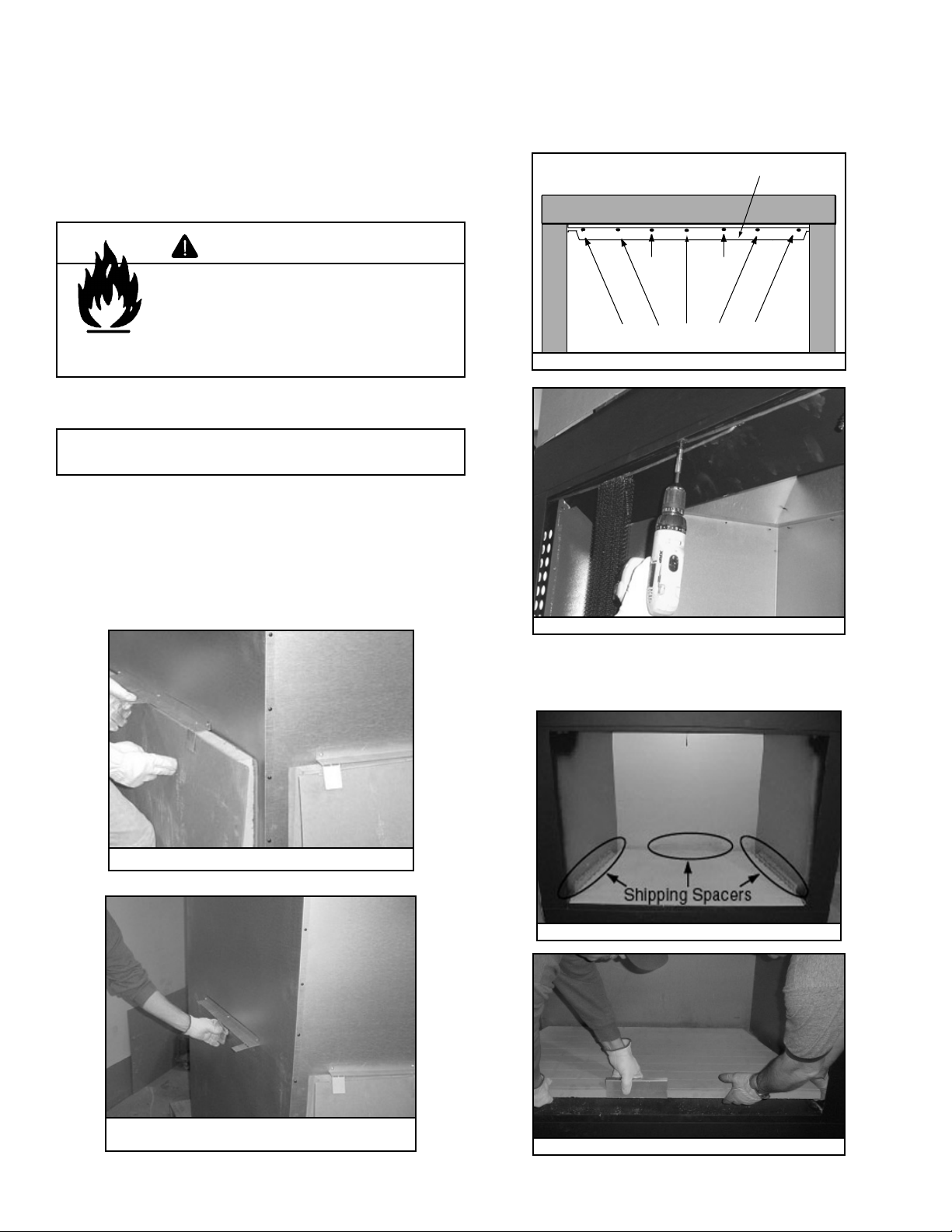
C. Install the Refractory
We recommend two installers for hearth stone and refractory installation!
• Remove back refractory from outside of fi replace by
bending tabs up and lifting refractory out of brackets.
See Figure 4.5. Bend tabs back down out of the way.
See Figure 4.6. Do not remove screws or brackets from
fi replace. If brackets are removed, fi ll holes in outer
shell with screws. Repeat this process to remove side
refractories.
Skip
Remove these screws.
Figure 4.7 Removing Smoke Shield
Figure 4.8 Removing the Screen Rods
Skip
• Remove hearth stone by removing three corrugated
shipping spacers (Figure 4.9). Lift hearth stone out of
fi replace. See Figure 4.10.
Figure 4.5 Unpacking Back Refractory
Figure 4.6 Bending Refractory Shipping Tabs
Back Down
Heatilator • I80 CAN-US • 4013-203 Rev F • 04/08
Figure 4.9 Shipping Spacers
Figure 4.10 Lifting Out the Hearth Stone
15
Page 16
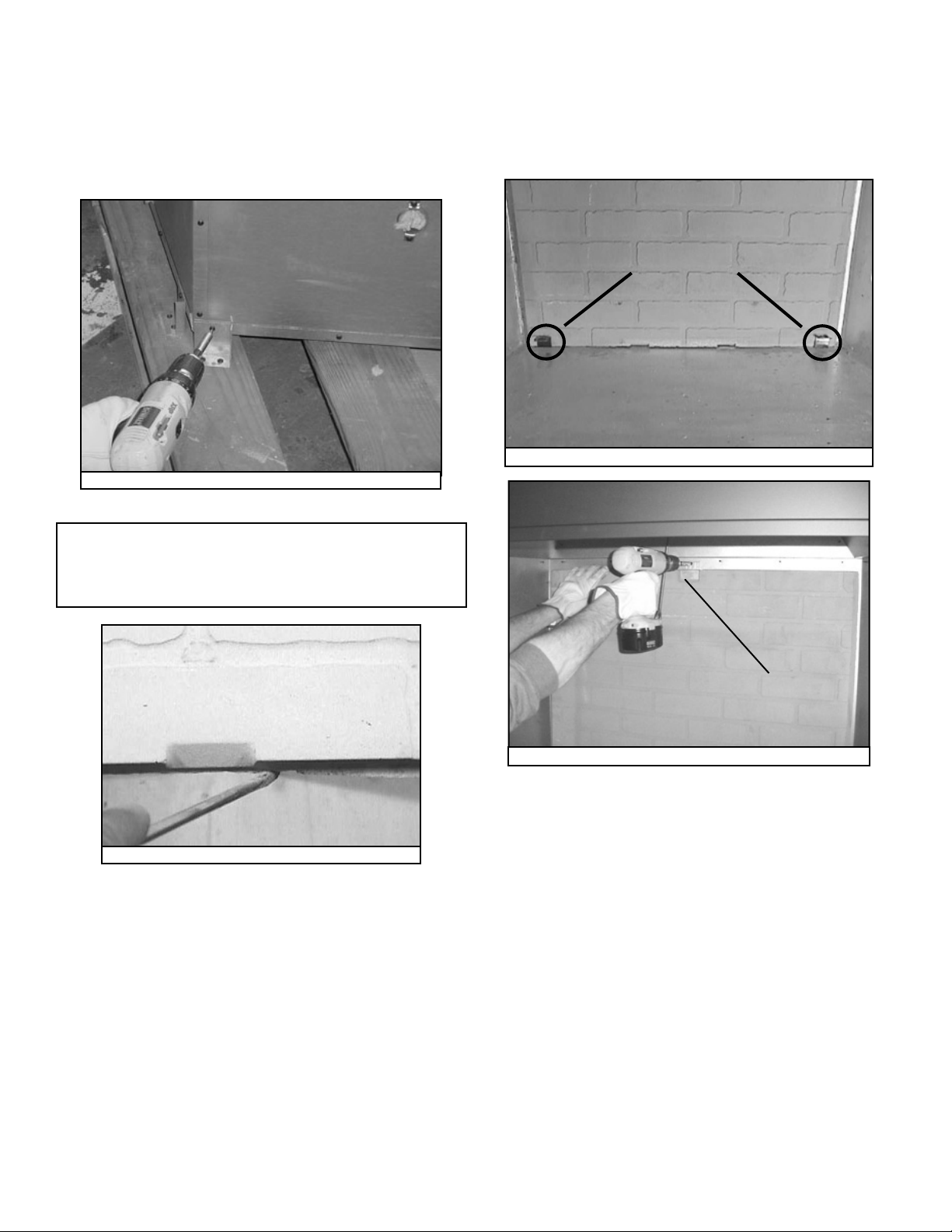
• Remove fi replace from pallet. The fi replace is attached
to pallet with two brackets on each side and rear of outer
shell. See Figure 4.11. Remove screws from bracket, pallet
and fi replace. Replace screws removed from fi replace.
Slide fi replace into position (brackets can be used to
anchor fi replace in position). Once fi replace has been put
into position, install refractories.
Figure 4.11 Removing Shipping Brackets
• Install back refractory, making sure refractory is
centered and notches are to the bottom of fi rebox. Place
grate brackets in outer two notches of refractory. See
Figure 4.13.
• Secure back refractory in place with a screw and bracket
supplied in hardware package. See Figure 4.14.
GRATE BRACKETS
Figure 4.13 Back Refractory with Grate Brackets in Place
Note: Before installing refractories and hearth stone, be
sure all back edges of each piece are smooth to ensure
proper fi t. Scrape away excess with a regular screwdriver.
See Figure 14.12.
Figure 4.12 Scrape Away Rough Edges
REFRACTORY
BRACKET
Figure 4.14 Attaching Back Refractory
16
Heatilator • I80 CAN-US • 4013-203 Rev F • 04/08
Page 17
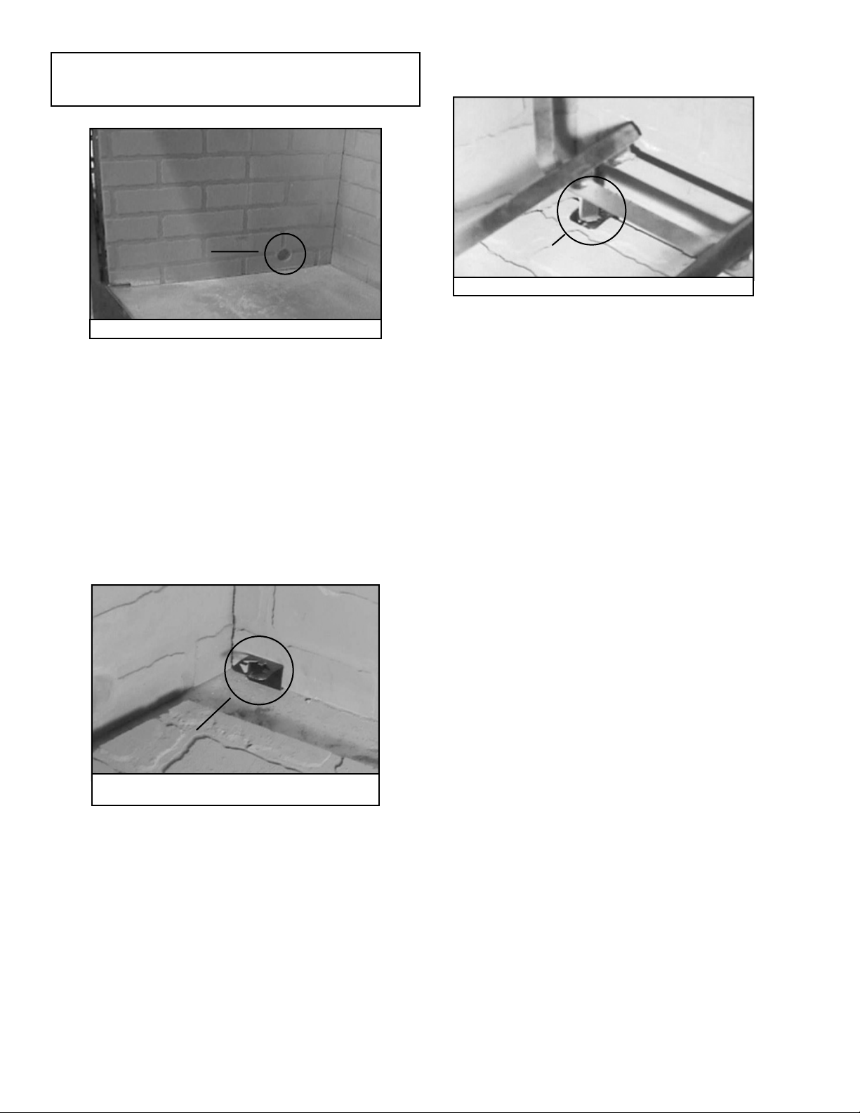
Note: To ensure proper installation, gas knockouts in the side
refractory should be positioned towards back of fi replace. See
Figure 4.15.
• Place grate into grate brackets. See Figure 4.17.
• Replace smoke shield.
GAS
KNOCKOUT
Figure 4.15 Gas Knockout
• Tilt top of side refractory towards center of fi rebox when
placing it into fi replace. Push side refractory towards
back corner of fi replace until it fi ts tightly against back
refractory.
• Secure side refractory in place with a screw and bracket
provided in the hardware package.
• Repeat these two steps for installation of the other side
refractory.
• When placing hearth stone into fi replace, slide it back
until it fi ts tightly against back refractory (underneath grate
brackets). See Figure 4.16.
GRATE
BRACKET
Figure 4.17 Grate Secured in Grate Bracket
• Replace left and right screens.
GRATE
BRACKET
Figure 4.16 Sliding Bottom Refractory Towards
Back of Fireplace
Heatilator • I80 CAN-US • 4013-203 Rev F • 04/08
17
Page 18

D. Place the Protective Metal Hearth Strips
WARNING
Fire Risk!
• Metal hearth strips MUST be installed.
Sparks or embers may ignite fl ooring.
Included with your fi replace you will fi nd two metal hearth strips
measuring approximately 26 in. x 4 in. (660 mm x 102 mm).
These strips are used to provide added protection where the
fi replace and the hearth extension meet.
Slide each metal strip 2 in. (51 mm) under the front edge of
the fi replace. The individual pieces must overlap each other
by 1 in. (25 mm) minimum in the middle of the fi replace to
provide continuous coverage of the fl oor. See Figure 4.18.
These metal strips should extend from the front and sides of
the fi replace opening by 2 in. (51 mm).
Note: When elevating the fi replace above the hearth exten-
sion the front of the elevated platform must be protected with
a protective metal hearth strip as shown in Figure 4.19.
1 in. overlap
Metal strips are placed 2 in. (51 mm) under the front
of the fireplace and must extend beyond the front
and sides of fireplace opening by 2 in. (51 mm)
Figure 4.18 Position the Protective Metal Hearth Strips
.
E. Level the Fireplace
Level fi replace side-to-side and front-to-back. Shim with
noncombustible material, such as sheet metal, as necessary. Secure fi replace (using nailing fl anges located on ei-
ther side of fi replace) to the vertical framing.
Important: To e n s u r e p r oper fi t of the glass doors, check
fi replace opening for square. Measure diagonal distances
of the opening to make sure they are equal. If they are not,
continue to shim fi replace until those diagonals are equal.
Top piece must overlap
bottom piece
Raised Platform
2 in.
(51 mm)
Floor
2 in.
(51 mm)
Figure 4.19 Protect the Front of an Elevated Platform
1 in. (25 mm) min.
overlap
18
Heatilator • I80 CAN-US • 4013-203 Rev F • 04/08
Page 19

5
Chimney Assembly
5
Chimney must extend
beyond combustible
roof structure
Maintain minimum
height of chimney
above roof
Install roof flashing
according to minimum
requirements
Offsets/returns
may not exceed
30° from vertical
Lock chimney
sections together
firmly to resist
movement
Termination Cap
Additional
support for
tall chimneys
Storm Collar
Maintain minimum
clearances to
combustibles as
specified
Support straps for offsets/
returns must be secured
to adequate framing
Ceiling firestops
are required where
chimney passes
through ceiling or
floor
Figure 5.1 Typical Chimney System - Guidelines for Chimney System Installation
NOTE:
• Chimney performance may vary.
• Trees, buildings, roof lines and wind conditions affect
performance.
• Chimney height may need adjustment if smoking or
overdraft occurs.
Heatilator • I80 CAN-US • 4013-203 Rev F • 04/08
19
Page 20

A. Chimney Requirements
Vertical distances are measured from the base of the fi re-
place as shown in Figure 5.2.
ft m
• Minimum overall straight height 18 5.5
• Minimum height with offset/return 18.5 5.6
•Maximum height 90 27.4
• Maximum chimney length between an offset and
return
• Maximum distance between chimney stabilizers 35 10.7
• Double offset/return minimum height 24 7.3
• Maximum unsupported chimney length between the
offset and return
• Maximum straight unsupported chimney height
above the fi replace
• Maximum unsupported chimney above roof 6 1.8
20 6
61.8
35 10.7
Note: A maximum of two pairs of offsets and returns may
be used.
WARNING
Fire Risk
• Must maintain 2 in. (51 mm) air clearance
to insulation and other combustible
materials.
To determine the chimney components needed to complete
your particular installation, follow the steps below:
• Determine the total vertical height of the fireplace
installation. This dimension is measured from the base of
the fi replace assembly to the point where the smoke exits
the termination cap.
• Subtract the effective height of the fi replace assembly from
the overall height of the fi replace installation (measured
from the base of the fireplace to the bottom of the
termination cap).
• Refer to Table 5.1 to determine what components must
be selected to complete the fi replace installation.
• Determine the number of ceiling fi restops, stabilizers,
roof flashing, etc. required to complete the fireplace
installation.
6 ft (1.8 m) max.
unsupported chimney
above roof
6 ft (1.8 m) max.
unsupported run
20 ft (6 m) max.
pipe between an
offset & return
Table 5.1
HEIGHT OF CHIMNEY
COMPONENTS in. mm
US Canada
Chimney Stabilizer
SL11 SL4 4-3/4 121
Ceiling Firestops
FS538 FS538 0 0
FS540 FS540 0 0
Offsets/Returns
SL1130 SL430 14-1/2 368
Roof Flashing
RF570 RF570 0 0
RF571 RF571 0 0
Chimney Sections*
SL1106 SL406 4-3/4 121
SL1112 SL412 10- 3/4 27 3
SL1118 SL418 16 - 3/4 42 5
SL1136 SL436 34-3/4 883
SL1148 SL448 46-3/4 1187
n/a SLA10 16-3/4 425
* Dimensions refl ect ef fective height.
Ceiling Firestop
11-10 in./279-254mm
adaptor required in
Canada
55-1/2 in.
(1410 mm)
Effective Height
(bottom of fireplace
to top of starter collar)
Figure 5.2 Chimney Requirements
35 ft (10.7 m)
max. straight
unsupported
chimney height
18.5 ft (5.6 m) min. height/single offset-return
24 ft. (7.3 m) min. height/double offset-return
90 ft (27.4 m) max. height
CAUTION
• Do NOT connect this fireplace to a chimney flue
servicing another appliance.
• Do NOT connect to any air distribution duct or
system.
20
Heatilator • I80 CAN-US • 4013-203 Rev F • 04/08
Page 21

B. Using Offsets/Returns
To bypass any overhead obstructions, the chimney may be
offset using an offset/return.
An offset and return may be attached together or a chimney
section(s) may be used between an offset and return.
Perform the following steps to determine the correct chimney component combination for your particular installation:
WARNING
Fire Risk
• Draft will be restricted if offset/return
greater than 30° are used.
Table 5.2
• Measure how far the chimney needs to be shifted to enable
it to avoid the overhead obstacle. See Figure 5.3. Use
dimension “A” to determine chimney section required to
achieve the needed shift.
• After determining the offset dimension, refer to Table 5.2
and fi nd the “A” dimension closest to but not less than the
distance of shift needed for your installation.
• The “B” dimension that coincides with the “A” dimension
represents the required vertical clearance that is needed
to complete the offset and return.
• Read across the chart and fi nd the number of chimney
sections required and the model number of those particular
chimney parts.
• Whenever the chimney penetrates a fl oor/ceiling, a ceiling
fi restop must be installed.
• The effective height of the fi replace assembly is measured
from the base of the fi replace to the top of the starter collar.
See Dimensions in Section 12.
AB
4 7/812417 7/8454-----
7 1/418422 5591----
9 3/4 248 26 1/8 664 2 - - - -
10 1/4 260 27 1/4 69 2 - 1 - - -
12 3/4 324 31 3/8 797 1 1 - - -
13 1/4 337 32 3/8 822 - - 1 - -
15 3/4 400 36 5/8 930 - 2 - - -
18 1/8 460 40 3/4 1035 1 2 - - -
18 3/4 476 41 3/4 1060 - 1 1 - -
21 3/4 552 47 1194 - - 2 - -
22 1/456548 1219---1-
24 3/4 629 52 1/8 1324 1 - - 1 -
27 3/4 705 57 3/8 1457 - 1 - 1 -
28 1/471858 3/81483----1
30 3/478162 1/215881---1
33 3/4 857 67 3/4 1721 - 1 - - 1
36 3/4 933 73 1854 - - 1 - 1
39 3/4 1010 78 1/8 1984 - - - 2 -
41 1/8 1045 82 3/8 2092 1 - - 2 -
45 3/4116288 1/22248---11
48 1/8 1222 92 3/4 2356 1 - - 1 1
51 3/4131498 7/82511----2
Proper assembly of air cooled chimney par ts results in an overlap of chimney joints
of 1-1/4 in. (32 mm). Effective length is built into this table.
SL1106
SL406
SL1112
SL412
SL1118
SL418
SL1136
SL436
SL1148
SL448in. mm in. mm
A
B
1-1/4 in. (32 mm)
OVERLAP
Figure 5.3 Chimney Offset/Return
Example: Your “A” dimension from
Figure 5.3 is 14 1/2 in. (368 mm).
Using Table 5.2 the dimension closest to, but not less than 14 1/2 in.
(368 mm) is 15 3/4 in. (400 mm) using
a 30° offset/return. It is then determined from the table that you would
need 36 5/8 in. (930 mm) (Dimension
“B”) between the offset and return.
The chimney components that best
fi t your application are two SL1112s
or SL412s.
Heatilator • I80 CAN-US • 4013-203 Rev F • 04/08
21
Page 22

C. Assemble the Chimney Sections
Attach either a straight chimney section or an offset to the
top of the fi replace (depending on your installation require-
ment, US only). Chimney sections are locked together by
pushing downward until the top section meets the stop bead
on the lower section.
The inner fl ue is placed to the inside of the fl ue section below
it. The outer casing is placed outside the outer casing of the
chimney section below it. See Figure 5.4.
Note: The ceiling fi restop MUST be nailed to the bottom
of the ceiling joists EXCEPT when the space above is
uninsulated and the attic insulation shield is not being used
(see Figure 5.5). When the attic insulation shield is used
the ceiling fi restop may be above or below the joist of an
insulated ceiling.
ROOM ABOVE (non-insulated ceiling)
B
A
Ceilng firestop from
bottom
ATTIC ABOVE (insulated ceiling)
Ceiling firestop from
top
When attic insulation
shield not used
Figure 5.4 Assembling Chimney Sections
Note: Inner fl ue and outer liner sections cannot be disas-
sembled once locked together. Plan ahead to ensure the
proper installation height is achieved with the selected
chimney components.
WARNING
Fire Risk
Do NOT install substitute or damaged
chimney components.
• MUST use chimney system described in
this manual.
• NO OTHER chimney components may
be used.
Substitute or damaged chimney components
may impair safe operation.
D. Install the Ceiling Firestops
• Mark and cut an opening in the ceiling for the ceiling
fi restop being used. See Figure 5.5.
• Frame the opening with the same size lumber used in the
ceiling joists.
• Install the ceiling fi restop.
Note: Use same dimensional lumber for framing
ceiling firestop and joists.
AB
Catalog #
FS538 17 432 17 432
FS540 17 432 26 660
Figure 5.5 Installing the Ceiling Firestop
in.mmin.mm
Note: You must provide support for the pipe during construction and check to be sure inadvertent loading has not
dislodged the chimney section from the fi replace or at any
chimney joint.
CAUTION
• Ceiling fi restops must be used at ceiling/fl oor.
• Chase construction requires ceiling fi restops at each
fl oor or every 10 ft (3.05 m) of clear space.
• Use same dimensional lumber as joists.
Ceiling fi restop slows spread of fi re and reduces cold air
infi ltration.
22
Heatilator • I80 CAN-US • 4013-203 Rev F • 04/08
Page 23

E. Install the Attic Insulation Shield
WARNING
Pipe
Tabs bent in to
rest against pipe
Fire Risk
• DO NOT pack insulation or other
combustibles: between ceiling fi restops;
between chimney and attic insulation
shield.
• ALWAYS maintain specifi ed clearances
around chimney and ceiling firestop
systems.
• Install ceiling fi restops as specifi ed.
Failure to keep insulation or other material
away from chimney pipe may cause fi re.
An insulation shield must be installed when there is a possibility of insulation coming into contact with the factory built
chimney system. Installation of a ceiling fi restop is required
(see Figures 5.7 and 5.8).
• Roll the shield (around the chimney if already installed)
until you have a 3 in. (76 mm) overlap and the three holes
on each side match up (large holes on top).
• Insert three screws into the matching holes to form a
tube.
• Bend three tabs on the bottom of the tube inward to 90°
to maintain chimney clearance. See Figure 5.6.
• Rest the insulation shield on the ceiling fi restop below.
• Bend the three short tabs at the top of the shield inward
to 90° to maintain the 2 in. (51 mm) clearance from the
chimney.
• Bend the remaining top tabs to just meet the pipe.
Attic Insulation Shield
17 in. (432 mm)
6 Tabs bent
in 90°
Insulation
13 in.
(330 mm)
Figure 5.7 Install Attic Insulation Shield Above the Ceiling
13 in.
(330 mm)
Pipe
Pipe
6 Tabs bent
in 90°
Pipe
diameter
Ceiling Firestop
Insulation
Tabs bent in to
rest against pipe
Attic Insulation Shield
17 in. (432 mm)
diameter
InsulationInsulation
Ceiling Firestop
Bend remaining tabs
to rest against pipe to
Bend inward
90°
prevent insulation
from falling in.
3 in. (76 mm)
overlap
Figure 5.6 Prepare Attic Insulation Shield
Heatilator • I80 CAN-US • 4013-203 Rev F • 04/08
Insert three
screws
Figure 5.8 Install Attic Insulation Shield Below the Ceiling
If you wish to make a custom shield or barrier, follow these
guidelines:
• Metal is preferred, although any material stiff enough to
hold up against the insulation can be used.
• The shield or barrier must be tall enough to extend above
the insulation and prevent blown-in insulation from spilling
into the cavity.
• Maintain specifi ed cleaances around chimney.
• Check instructions and local codes for further details.
23
Page 24

F. Double-check the Chimney Assembly
Continue assembling the chimney sections up through the
ceiling fi restops as needed. While doing so, be aware of the
height and unsupported chimney length limitations given under Section 5.A. Chimney Requirements.
Check each section by pulling up slightly from the top to ensure proper engagement before installing the succeeding
sections. If they have been connected correctly, they will not
disengage when tested.
G. Secure the Chimney
When offsets and returns are joined to straight pipe sections,
they must be locked into position with the screws provided*
(outer only), using the predrilled holes. To prevent gravity
from pulling the chimney sections apart, the returns and the
chimney stabilizers have hanger straps for securing these
parts to joists or rafters. See Figure 5.9.
* or equivalent #6 or #8 sheet metal screw no longer than
3/4 in. (19 mm).
WARNING
Fire Risk
• Secure offsets with screws (not to exceed
3/4 in./19 mm in length).
• Secure returns with strapping.
• Straight chimney sections may be secured with screws
(not to exceed 3/4 in./19 mm in length) at the joints.
Keep chimney sections from separating or twisting.
Straps
Optional
Additional
Support
Figure 5.9 Secure the Chimney
Ceiling
Firestop
Joint
Band
(Optional)
24
Heatilator • I80 CAN-US • 4013-203 Rev F • 04/08
Page 25

6
Complete the Enclosure
6
A. Chimney Termination
Chimney Termination Requirements (See Figure 6.1)
• Must have a cap approved and listed for this fi replace system
• Must not be located where it will become plugged by snow or other material
• Must terminate at least 3 ft (914 mm) above the roof and at least 2 ft (610 mm) above any portion of the roof within 10 ft
(3.05 m)
• Must be located away from trees or other structures
Slanted Roofs
Chimney must extend 2 ft (.6 m)
Chimney must
extend 3 ft (.9 m)
above the roof
above any portion of the roof or
adjacent structures within
10 ft (3 m) of the chimney
Flat Roofs
Chimney must
extend 3 ft (.9 m)
above the roof
Termination Requirements
Gas, Wood or Fuel
Oil Termination
18 in.
(457 mm)
Gas
Termination
Chimney must extend 2 ft (.6 m)
above any portion of the roof or
adjacent structures within
10 ft (3 m) of the chimney
Gas, Wood or Fuel
Oil Termination
See
illustration
A
above for wood
B
Wood
Gas
Fuel Oil
Termination
20 in. min. *
(508 mm)
See
illustration
above for wood
Termination Caps Staggered Height
A Gas Termination Wood or Fuel Oil Termination
B 6 in.
Multiple Chimney Locations
Figure 6.1 Termination Requirements
¨
(152 mm) min. 20 in. (508 mm) min.
Heatilator • I80 CAN-US • 4013-203 Rev F • 04/08
Termination Caps Same Height
* If using decorative cap cover(s), this distance may
need to be increased. Refer to the installation instruc tions supplied with the decorative cap cover.
25
Page 26

Mark the Exit Point of the Roof
Locate the point where the chimney will exit the roof by
plumbing down to the center of the chimney. Drive a nail
up through the roof to mark the center. See Figure 6.2.
Cut Out the Hole in the Roof
Measure to either side of the nail and mark the 17 in.
x 172 in. (432 mm x 432 mm) opening required. This is
measured on the horizontal; actual length may be larger
depending on the pitch of the roof. Cut out and frame the
opening. See Chapter 25 of the Uniform Building Code
for roof framing details.
WARNING
Fire Risk
• Must maintain 2 in. (51 mm) air clearance
to insulation and other combustible
materials.
Assemble the Chimney Sections Through the
Roof
Continue to add chimney sections through the roof opening, maintaining at least a 2 in. (51 mm) air space to combustible materials.
Install the Roof Flashing
If a roof fl ashing is to be used, install the roof fl ashing
appropriate to the roof pitch and install a round termination
cap and storm collar following the instructions shipped with
the cap.
Install the Chimney Air Kit (required in Canada)
When installing the chimney air kit, follow the instructions
provided with this accessory.
Figure 6.2 Ceiling/Attic Construction
26
Heatilator • I80 CAN-US • 4013-203 Rev F • 04/08
Page 27

B. Chase Top
A metal chase top is required to seal the top of the chase
around the chimney pipe. The top should include a turndown and drip edge to prevent water from seeping into the
chase. Provide a 1/8 in. (3 mm) gap around the fl ue pipe
and slope the top downward away from the penetration. See
Figure 6.3.
• All seams must be caulked to prevent leaks.
• A chase installation must use a chase top. Chase tops
are available from your Heatilator dealer or may be fi eld
constructed.
• Attach the chase top to the top of the chase.
Termination Cap
2 in. (51 mm) Collar
Caulk
on Chase Top
Storm Collar
• Install the chimney sections up through the chase
enclosure. When using a TR11 or TR444 Round
Termination Cap, the uppermost top section of pipe must
extend 6 in. (152 mm) above the top of the fl ashing collar
to allow installation of the storm collar and termination cap.
See Figure 6.4.
Minimum 1-1/2 in. (38 mm) overlap of cap over pipe
Storm Collar
2 in. (51 mm) min.
6 in. (152mm) min.
Flashing Collar
Figure 6.4 Installing a TR11 or TR444 Round Termination Cap
2 in. (51 mm) min. collar
Slope Downward
Turn-down
Drip Edge
Chase
(Chimney)
.018 (26 ga) min.
Galvanized
Chase Top
Figure 6.3 Chase Top Construction
C. Install the Termination Cap
Note: To protect against the effect of corrosion on those
parts exposed to the weather, the termination cap can be
painted with a rust-resistant paint.
WARNING
• For installations utilizing a TR11T or TR442 Round
Telescoping Termination Cap, the uppermost chimney
section must be below the top of the chase top, but not
more than 14-1/2 in. (368 mm) below the top of the chase
top. Minimum overlap of chimney and termination cap
must be 1-1/2 in. (38 mm). See Figure 6.5.
Storm Collar
Flashing Collar
Top of Pipe
Figure 6.5 Installing a TR11T or TR442 Round Telescoping Termi-
nation
Cap
2 in. (51 mm) min.
14-1/2 in. (368mm) max.
1-1/2 in. (38 mm) min.
overlap
Fire Risk
• The minimum overlap of cap to pipe
MUST be met or chimney may separate
from cap.
Separation allows sparks, heat and embers
to escape.
Heatilator • I80 CAN-US • 4013-203 Rev F • 04/08
27
Page 28

• For installations utilizing an ST1175 or ST475 Square
Termination Cap the last chimney section must not be
more than 4-1/2 in. (114 mm) below the chase top. See
Figure 6.6.
Flashing Collar
Cap Standoff
2 in. (51 mm) min.
• For chase installations you can use a TR11 or TR444
Round Termination Cap, a TR11T or TR442 Round
Telescoping Termination Cap, an ST1175 or ST475 Square
Termination Cap, or a TCT1175 Terra Cotta Termination
Cap.
• For installations utilizing a European Copper Series
Termination Cap, See Figure 6.8.
1-1/2 in.
(38 mm) min.
overlap
Figure 6.6 Installing an ST1175 or ST475 Square Termination Cap
•
For installations utilizing an TCT1175 Terra Cotta Cap the
Top of Pipe
4-1/2 in.
(114 mm)
max.
last chimney section must be between 7 in. (178 mm) below
the chase top and 2 in. (51 mm) above. See Figure 6.7.
The last section of pipe
must stop between the
1-1/2 in. (38 mm)
min. overlap
distances given below.
2 in. (51 mm) above top
of the chase.
{
7 in. (178 mm) below top
Top of Pipe
of the chase.
Cap Base
(cap inner flue)
bracket (8)
screw (8)*
chimney top
chase
top
(metal or masonry)
Figure 6.8 Installing a European Copper Series Termination Cap
SL pipe
inner flue
(CT11-King shown, available in US only)
2 - 6 in.
(51-152 mm)
2 in. (51 mm)
typical
Figure 6.7 Installing a TCT1175 Terra Cotta Cap (available is US
only)
• Install termination caps following instructions provided
with them.
28
Heatilator • I80 CAN-US • 4013-203 Rev F • 04/08
Page 29

7
Accessories
7
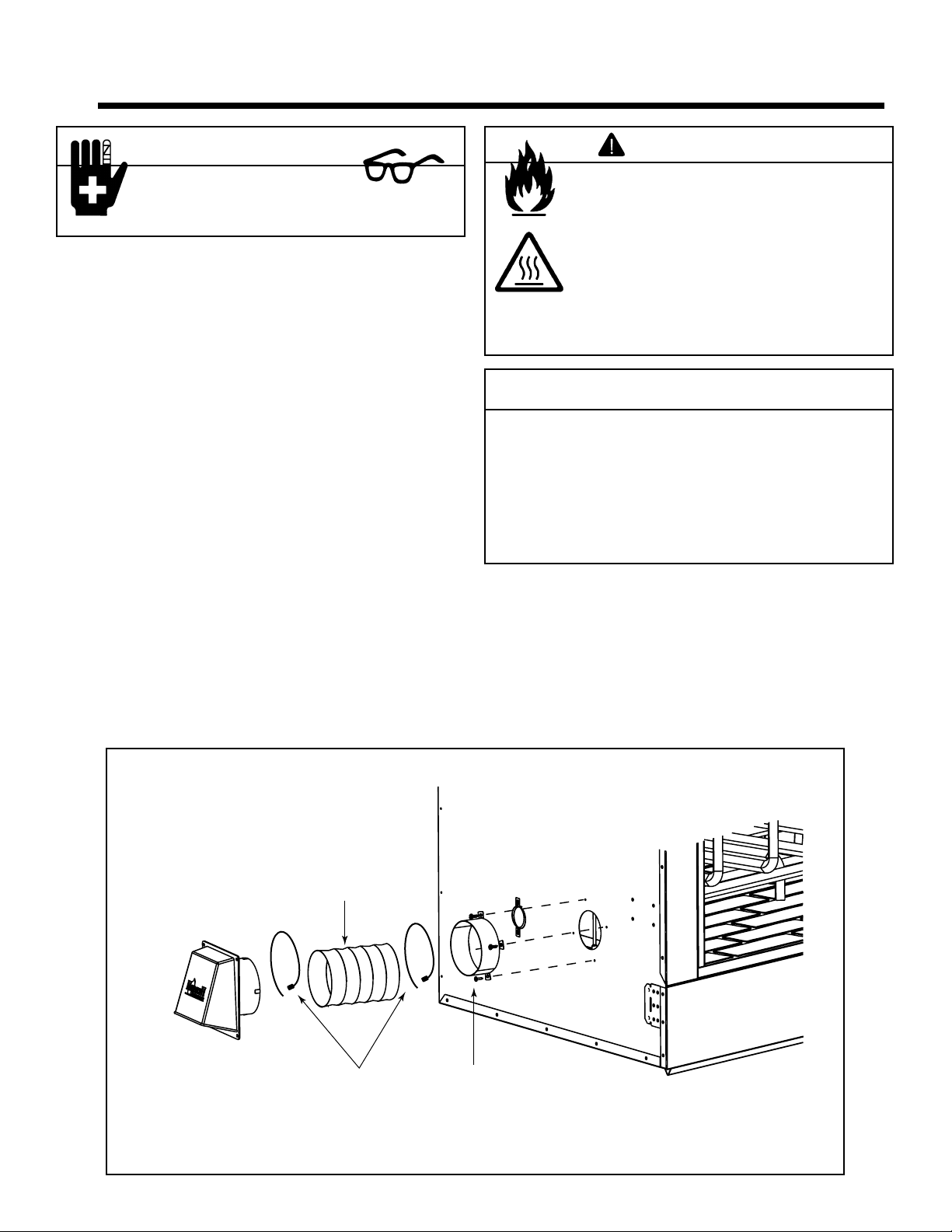
A. Gas Log/Lighter Provisions
A certifi ed gas log lighter or decorative gas log set can be
installed in this fi replace.
• Maximum input is 100,000 BTU/hr.
• Decorative gas appliance must be certifi ed to ANSI Z21.60
“Standard for Decorative Gas Appliances for Installation
in Vented Fireplaces”.
• Must be installed in accordance with the National Fuel
Gas Code, ANSI Z223.1.
• A log set must incorporate a gas shutoff.
• Log set requires the damper to be locked fully open.
Knockouts are provided on both sides of the fi replace and in
refractories for 1/2 in. (13 mm) iron pipe.
• We recommend you seal refractory around pipe with
fi replace mortar or high temperature, noncombustible
sealant.
• Repack insulation from the knockout around the pipe.
• Maintain 1-1/2 in. (38 mm) air space around the pipe for
4 in. (102 mm) beyond the fi replace.
• See Figure 7.1.
Outer Shell
Firebox
of Fireplace
Maintain air clearance
to combustibles.
WARNING
Asphyxiation Risk
• Damper must be locked open when gas logs
installed.
Gas fi re generates fumes.
WARNING
Fire Risk
• For use with solid wood fuel or decorative
gas appliance only.
• DO NOT install unvented gas logs.
WARNING
Fire Risk
Explosion Risk
Inspect appliance and components for
damage. Damaged parts may impair safe
operation.
• Do NOT install damaged components.
• Do NOT install incomplete components.
• Do NOT install substitute components
Report damaged parts to dealer.
Refractory
Seal with
fireplace mortar
or high temp
noncombustible
sealant
Gas Line
Repack
Insulation
Knockout
Figure 7.1 Gas Line Installation
Gas Line
4 in.
(102 mm)
Combustible
Materials
1-1/2 in.
(38 mm)
air space
Combustible materials
may be located at zero
clearance to gas line
beyond 4 in. (102 mm)
from fireplace side.
Heatilator • I80 CAN-US • 4013-203 Rev F • 04/08
29
Page 30

8
Finishing
8
A. Hearth Extension
A hearth extension must be installed with all fi replaces to
protect the combustible fl oor in front of the fi replace from
both radiant heat and sparks. See Figures 8.1 -8.5.
High temperature
(300°F min.) continuous,
HX3 or HX4
Hearth Ext
or equivalent
insulation
(see Table below)
non-combustible sealant
Tile, stone or other
non-combustible material
Protective
Fireplace
Metal Hearth
Strip
2 in. (51 mm)
Floor constructed of wood or
other combustible material
Figure 8.1 Hearth Extension Construction
required
WARNING
Fire Risk
• Metal hearth strips MUST be installed.
Sparks or embers may ignite fl ooring.
This fi replace has been tested and approved for use with a
hearth extension insulated to a minimum R value of 1.03.
To substitute materials for the factory-available hearth extensions, calculate insulation alternatives as per Table 8.1
and the following formulas:
• Thermal conductivity per inch thickness = k
• k = (BTU)(inch) / (foot2)(hour)(°F)
• Required thickness = Rk
• Thermal resistance per inch thickness = r
• r = (foot2)(hour)(°F) / (BTU)(inch)
• Required thickness = R / rB.
1 in. overlap
Metal strips are placed 2 in. (51 mm) under the front
of the fireplace and must extend beyond the front
and sides of fireplace opening by 2 in. (51 mm)
Figure 8.2 Positioning the Protective Metal Hearth Strips
.
WARNING
Fire Risk
• Hearth extensions must be installed
exactly as specifi ed.
High temperatures or hot embers may ignite
concealed combustibles.
Table 8.1
Hearth Extension Insulation Alternatives-Total minimum R Value must equal 1.03
Material
Hearth & Home HX3, HX4 (Micore 300™) 0.49 2.06 1/2 in.
USG Micore 160™ 0.39 2.54 1/2 in.
USG Durock™ Cement Board 1.92 0.52 2 in.
Cement Mortor 5.0 0.20 5-1/8 in.
Common Brick 5.0 0.20 5-1/8 in.
Ceramic Tile 12.50 0.08 12-1/4 in.
Armstrong™ Privacy Guard Plus 0.46 2.18 1/2 in.
Marble 14.3-20.0 0.07-0.05 14-5/8 in. - 20-3/8 in.
30
k per inch
thick
Heatilator • I80 CAN-US • 4013-203 Rev F • 04/08
r per inch
thick
Minimum
thickness
required
Page 31

A
Figure 8.3 Hearth Extension Dimensions
12 in.
Min.
12 in.
C
20 in.
Min.
Min.
CAT. # A B C
HX3 in 52 16 8
mm 1321 40 6 203
HX4 in 66 20 12
mm 1676 508 305
B
Note: Maximum height from floor
under fireplace to top of finished
hearth extension is 7-5/8 in. (195 mm)
20 in.
(508 mm) Min.
Floor
Micore
Hearth Extension
Hearth Strip
Noncombustible Material
Figure 8.4 Raised Hearth Extension
12 in.
Min.
12 in.
Min.
Figure 8.5 Flush Hearth Extension
30 in. min.
Note: Maximum height from floor
under fireplace to top of finished
hearth extension is 7-5/8 in.
Floor
Micore
30 in. Min.
Hearth Extension
Noncombustible Material
Hearth Strip
Heatilator • I80 CAN-US • 4013-203 Rev F • 04/08
31
Page 32

B. Finishing Material
• Combustible Material
Material which is made of or surfaced with wood,
compressed paper, plant fi bers, plastics, or any material
capable of igniting and burning, whether fl ame proofed or
not, plastered or not plastered.
• Non-Combustible Material
Material which will not ignite and burn. Such materials are
those consisting entirely of steel, iron, brick, tile, concrete,
slate, glass or plasters, or any combination thereof.
Materials that are reported as passing ASTM E 136,
Standard Test Method for Behavior of Materials in a
Vertical Tube Furnace at 750° C, shall be considered
non-combustible materials.
• Non-Combustible Sealant Material
Sealants which will not ignite and burn: Rutland, Inc.
Fireplace Mortar #63 (or equivalent), Rutland 76R, Nufl ex
302, GE RTV116, GE RTV106 (or equivalent).
After completing the framing and applying the facing material
(drywall) over the framing, a bead of non-combustible sealant must be used to close off any gaps at the top and sides
between the fi replace and facing to prevent cold air leaks.
Large gaps can be bridged with fi berglass rope gasket.
Only non-combustible materials may be used to cover the
metal fi replace front.
WARNING
Fire Risk
• Maintain clearances.
• Use only non-combustible material below
standoffs, material such as cement board is
acceptable.
• Framing or fi nishing material used on the front of, or
in front of, the appliance closer than the minimums
listed, must be constructed entirely of noncombustible
materials (i.e., steel studs, concrete board, etc.).
Check for proper
chimney alignment
Maintain clearance (air
spaces) to insulation and
framing as specified
Secure fireplace to
framing and make plumb
Provide firm support
for entire system
Install outside air
(as required)
Keep framing and
combustibles at
assigned clearances
(do not notch framing)
Seal with noncombustible material at
top edge of fireplace.
Maintain clearances
to combustibles
around fireplace
Use only noncombustible materials
over facing around
opening (unless
otherwise specified)
Do not cover air
grilles or openings
Install protective
metal sealing strip(s)
Figure 8.6 Guidelines for Framing and Enclosing
32
Heatilator • I80 CAN-US • 4013-203 Rev F • 04/08
Extend hearth extension materials
to specified distance - use materials that meet or exceed minimum
required insulating values
Page 33

C. Mantel
A combustible mantel may be positioned no lower than
12 in. (305 mm) above the top of the fi replace opening. The
combustible mantel may have a maximum depth of 12 in.
(305 mm). Combustible trim pieces that project no more
than 1-1/2 in.(38 mm) from the face of the fi replace can
be placed no closer than 6 in. (152 mm) from the top of the
fi replace opening. See Figure 8.7. Combustible trim must
not cover the metal surfaces of the fi replace. This mantel
clearance is in accordance with Section 7-3.3.3 of ANSI/
NFPA211.
D. Sidewalls/Surrounds
Adjacent combustible side walls must be located a minimum
of 24 in. (610 mm) from the fi replace opening. If you are us-
ing a decorative surround constructed of combustible material, it must be located within the shaded area defi ned in
Figure 8.8. Short stub walls are also acceptable if they are
contained within the shaded area.
WARNING
Fire Risk
Do NOT obstruct air inlets.
Do NOT modify air inlets.
• Modifying or covering air inlets could cause
temperature rise and fi re hazard.
Finishing materials must not interfere with:
• Air inlets
• Access for service
4 in.
(102 mm)
19-3/4 in.
(502 mm)
39°
FLUSH FRONT
23 in.
(584 mm)
50°
24 in.
(610 mm)
Figure 8.8 Sidewalls/Surrounds
¨
BRICK
FRONT
42 in.
(1067 mm)
50-1/2 in.
(1283 mm)
24 in.
(610 mm)
WARNING
Fire Risk
Finish all edges and fronts to clearances and
specifi cations.
• Metal fireplace front may be covered with noncombustible material only.
• Do NOT overlap combustible materials onto fi replace
front.
• Install combustible materials up to specifi ed clearances
on top front and side edges.
• Seal joints between the fi nished wall and fi replace top
and sides using only a 300° F minimum sealant.
E. Glass Doors
This fi replace has been tested and listed for use with doors
as specifi ed in Section 12.B. Fireplace Components. Please
refer to the manual packed with each set of doors for installation instructions.
12 in.
12 in. MIN.
Gas Knockout
Figure 8.7 Mantel Specifi cations
55-1/2 in.
Effective
Height
Heatilator • I80 CAN-US • 4013-203 Rev F • 04/08
33
Page 34

9
Operating Instructions
9
WARNING
Fire Risk
• Do not operate fireplace before
reading and understanding operating
instructions.
Failure to operate fi replace properly may
cause fi re.
A. General Information
Fireplaces, as well as other woodburning appliances, have
been used safely for many years. It has been our experience
that most problems are caused by improper installation and
operation of the fi replace. Make certain that installation and
operation of the fi replace system is in accordance with these
instructions.
It is extremely important that the fi re be supervised when-
ever the fi replace is in use. It is also recommended that an
annual inspection be performed on the fi replace system to
determine if the fl ue system needs to be cleaned, or as in
the case of any appliance, if minor repairs are required to
maintain the system in top operating condition.
WARNING
HOT SURFACES!
Glass and other surfaces are
hot during operation AND cool
down.
Hot glass will cause burns.
• Do not touch glass until it is cooled
• NEVER allow children to touch glass
• Keep children away
• CAREFULLY SUPERVISE children in same room as
fi replace.
• Alert children and adults to hazards of high
temperatures.
High temperatures may ignite clothing or other
fl ammable materials.
• Keep clothing, furniture, draperies and other
fl ammable materials away.
WARNING
Fire Risk
• For use with solid wood fuel or decorative gas
appliance only.
• Do not install unvented gas logs.
34
DAMPER
UP = open
DOWN = close
AIR KIT
UP = open
DOWN = closed
Figure 9.1 General Operating Parts
Heatilator • I80 CAN-US • 4013-203 Rev F • 04/08
Page 35

B. Outside Air
A source of air (oxygen) is required in order for combustion
to take place. Whatever air is consumed by the fi re must be
replaced through cracks around windows, under doors, etc.
Most newly constructed houses or existing homes fi tted with
tightly sealed doors and windows are relatively air tight. In
this case, an outside air source must be made available to
feed combustion air from outside the home.
An outside air control handle allows you control of the outside air inlet if your fi replace is equipped with this option.
Use of outside air for combustion is highly recommended to
conserve heated air within the structure and to provide make
up air to keep the fi replace venting properly.
This fi replace will operate correctly only if adequate ventila-
tion is provided to allow proper draft to the fi replace sys-
tem.
See Figure 9.1 for location and operation.
CAUTION
Outside air control handle is HOT. Adjust before lighting
fi re.
C. Clear Space Near the Fireplace
Combustible materials must not be stored on the hearth extension. Room furnishings such as drapes, curtains, chairs
or other combustibles must be at least 4 ft (1.22 m) from the
open front of the fi replace.
E. Firescreen
A fi rescreen is always provided to control sparks. It must
be closed whenever the fi replace is in use. Glass doors or
fi rescreens must not be used to hold burning material inside the fi replace. Only those glass doors specifi cally tested
and listed for use with the specifi c fi replace model should be
used. Screens should be closed when the glass doors are
closed.
WARNING
Fire Risk
• Close fi rescreen when burning fi replace.
• Do not use fi rescreen or glass doors to
hold burning material in fi replace.
Firescreen controls sparks.
Glass may break or burning material may
roll out.
F. Glass Doors
Most effi cient fi replace operation using glass doors is with
the doors open. When the doors are open the screen must
be closed. Only Hearth & Home Technologies glass doors
may be used. See Figure 9.2 for proper glass door operation.
FULLY OPEN
CORRECT
PARTLY OPEN
INCORRECT
D. Flue Damper
The fl ue damper must be in full open position, and is oper-
ated by moving the handle up toward the top of the fi replace.
Before lighting the fi re, verify this by looking up from the in-
side of the fi replace. Always operate this fi replace with the
damper fully open. Please note: Down drafts, obstructions,
damaged or poor (wet) fuels can cause smoke spillage.
See Figure 9.1 for location and operation.
WARNING
Asphyxiation Risk
Fire Risk
• Open damper to operate fi replace.
Closed damper will over-fi re fi replace and
prevent venting of combustion gases.
FULLY CLOSED
CORRECT
Figure 9.2 Proper Operating Positions of Bi-fold Doors
PARTLY CLOSED
INCORRECT
WARNING
Fire Risk
Smoke Risk
• Doors must be fully opened or fully closed
when operating fi replace.
Partially opened doors may draw fl ame, smoke
or heat from fi replace.
Heatilator • I80 CAN-US • 4013-203 Rev F • 04/08
35
Page 36

G. Grate
The factory installed integral grate must be used to hold the
logs from falling out of an open fi replace and to allow air to
pass between the burning logs. It is important to keep the fi re
off the hearth and to allow the ashes to collect beneath the
fi re, thereby forming a layer of additional heat protection.
WARNING
Fire Risk
• Use only factory installed integral grate.
May cause overfi re.
H. Wood Fuel
Firewood
Your fi replace performance depends on the quality of the
fi rewood you use. All seasoned wood, regardless of spe-
cies, contains about 8,000 BTU’s per pound, and hardwoods have a greater density than soft woods. A piece
of hardwood will contain about 60% more BTU’s than
an equal size piece of soft wood. Firewood is commonly
sold by the cord (128 cu. ft.). A cord of seasoned oak
(hardwood) would contain about 60% more potential energy than a cord of seasoned pine (soft wood).
Examples of soft wood trees are Douglas fi r, pine, spruce,
and cedar, poplar, aspen and alder. Soft woods require
less time to dry, burn faster and are easier to ignite than
hardwoods.
Examples of hardwood trees are oak, maple, apple, and
birch. Hardwoods require more time to season, burn
slower and are usually harder to ignite than soft woods.
The best wood fuel is a combination of soft wood and
hardwood. Start the fi re with soft wood; the fi re will give
off quick heat to bring the fi replace up to operating tem-
perature, and then the hardwood can be added for slow,
even heat and longer burn time.
Moisture
Regardless of which species of wood you burn, the single
most important factor that effects the way your fi replace
operates is the amount of moisture in the wood. The majority of the problems fi replace owners experience are
caused by trying to burn wet, unseasoned wood.
Freshly cut wood can be as much water as it is wood,
having a moisture content of around 50%. Imagine a
wooden bucket that weighs about eight pounds. Fill it
with a gallon of water, put it in the fi replace and try to burn
it. This sounds ridiculous but that is exactly what you are
doing if you burn unseasoned wood.
Seasoning
Seasoned fi rewood is nothing more than wood that is
cut to size, split and air dried to a moisture content of
around 20%. The time it takes to season wood varies
from around nine months for soft woods to as long as
eighteen months for hardwoods. The key to seasoning
wood is to be sure it has been split, exposing the wet
interior and increasing the surface area of each piece. A
tree that was cut down a year ago and not split is likely
to have almost as high a moisture content now as it did
when it was cut.
The following guideline will ensure properly seasoned
wood:
• Stack the wood to allow air to circulate freely around
and through the woodpile.
• Elevate the woodpile off the ground to allow air
circulation underneath.
• The smaller the pieces, the faster the drying process.
Any piece over 6 in. (152 mm) in diameter should be
split.
• Cover the top of the woodpile for protection from
rain and snow. Avoid covering the sides and ends
completely. Doing so may trap moisture from the
ground and impede air circulation.
The problems with burning wet, unseasoned wood are
twofold: First, you will receive less heat output from wet
wood because it requires energy in the form of heat to
evaporate the water trapped inside. This is wasted energy that should be used for heating your home. Secondly,
this moisture evaporates in the form of steam which has
a cooling effect in your fi replace and chimney system.
When combined with tar and other organic vapors from
burning wood it will form creosote which condenses in
the relatively cool fi replace and chimney.
WARNING
Fire Risk
• Do NOT burn wet or green wood.
• Store wood in dry location.
• Stack wood so both ends are exposed to
air.
Wet, unseasoned wood can cause
accumulation of creosote.
WARNING
Fire Risk
Do NOT store wood:
• Closer than required clearances to
combustibles to fi replace.
• Within space required for loading or ash
removal.
36
Heatilator • I80 CAN-US • 4013-203 Rev F • 04/08
Page 37

I. Starting a Fire
Check the fl ue damper to be certain it is in the full open po-
sition. Place crumpled or twisted paper under the fi replace
grate. Loosely arrange kindling or small pieces of wood to
form a layer above the paper.
The fi res must be built on the fi replace grate, without danger
of the burning fuel falling out of the fi replace opening.
Light the paper and add small pieces of wood until a hot bed
of embers has been established.
After establishing the fi re bed, and the small fi rewood is burn-
ing briskly, add a minimum of three average sized pieces of
split fi rewood, place the wood in such a manner to allow
combustion air and fl ames between them.
Note: When fi rst lighting your fi replace, it may be neces-
sary to pre-warm the fl ue to establish a draft. This is done
by holding a rolled up piece of burning newspaper under
the fl ue damper for a few moments. This will help reduce
smoke spillage during start-up.
Note: The fi rst three or four fi res should be of moderate
size to allow the oils and binders to be burned from the
fi replace and the refractory and paint to cure. You may
notice an industrial odor the fi rst few fi res. This is consid-
ered normal.
CAUTION
Odors and vapors released during initial
operation.
• Curing of high temperature paint.
• Open windows for air circulation.
Odors may be irritating to sensitive individuals.
WARNING
Fire Risk
Keep combustible materials, gasoline and
other fl ammable vapors and liquids clear of
fi replace.
• Do NOT store fl ammable materials close
to the fi replace.
• Do NOT use gasoline, lantern fuel,
kerosene, charcoal lighter fl uid or similar
liquids to start or “freshen up” a fi re in this
fi replace.
• Keep all such liquids well away from the
fi replace while it is in use.
Combustible materials may ignite.
Heatilator • I80 CAN-US • 4013-203 Rev F • 04/08
37
Page 38

10
10
Troubleshooting
This fi replace will operate correctly only if adequate ventila-
tion is provided to allow proper draft to the fi replace system.
Hearth & Home Technologies assumes no responsibility for
the improper performance of the fi replace system caused
by inadequate draft due to environmental conditions, down
drafts, tight sealing construction of the structure, or mechanical exhausting devices which will create a negative air pressure within the structure where the fi replace is located.
A. Understanding Vent Problems
If smoke spillage occurs from a fi replace opening when the
door is open and the proper chimney height, fl ue size, and
confi guration requirements for the installation have been
met, there is either a leakage in the fl ue, a blockage in the
?
n
o
i
t
a
n
i
m
r
e
t
y
e
n
m
i
h
c
d
n
u
o
r
a
s
d
n
i
w
g
n
o
r
t
S
Another appliance in
home also exhausting
air (furnace, fan,
dryer, etc.)?
Unsealed
can lights?
fl ue, or some condition is in effect to draw smoke from the
fi replace into the house. Understanding and differentiating
the conditions which can cause each of these kinds of spillage problems is essential to their solution.
• Flue Leakage
Check for improperly connected fl ue joints or a damaged
fl ue joint in the chimney system. Such leakage would
reduce draft (air would be drawn in through the leaks rather
than through the fi replace). The result might be diffi cult
start-up and smoky fi res that might spill if other adverse
draft conditions accompany this problem.
• Flue Blockage
The damper should be open.
Overhanging
tree?
Bird's nest
or leaves in
termination
cap?
Structural
changes in
chimney area?
Overhead fan
operating?
Air register from
furnace near
fireplace?
Doors opening
and closing?
Window closed
for start-up?
Figure 10.1 Factory-built Fireplaces: Troubleshooting
38
Heatilator • I80 CAN-US • 4013-203 Rev F • 04/08
Creosote buildup
in flue?
Damper closed?
Outside air
closed?
Page 39

B. Diagnostics and Problem Solving
I can’t get a good fi re going. What am I doing wrong?
Diagnostic Questions Possible Causes of Condition Solutions
Is the damper open? • No draft Open damper.
Is there enough paper/starter? • Insuffi cient heat to ignite kindling Use more paper/starter.
Is there enough kindling?
Is the kindling dry?
Is there enough or too much
wood? Is it too large? Is it dry
enough?
Are there adequate air spaces
between fuel pieces?
Is the chimney pre-warmed? • Exposed, cold chimney down drafting Use lighted rolled newspaper at throat or fl ue opening to start
Is there smoke in the house? • Damper closed Check damper; have chimney checked if it worked previously;
Does the kindling, wood not
ignite?
Does the kindling ignite, but the
fuel doesn’t?
Does the fuel ignite, but not
burn well?
• Insuffi cient heat to ignite fuel Use more dry kindling.
• Insuffi cient heat to establish draft Use small split wood that is well seasoned (split, covered on top at
• Insuffi cient air passage
• Insuffi cient surface area
• Ignition temperature high due to moisture
• Insuffi cient combustion air and exposed
surface area
• Obstruction in chimney
• Down draft from chimney temperature or
from negative house pressure
• Condition, amount, arrangement of kindling
and fuel
• Amount of kindling Use more kindling; use smaller, dry wood.
• Condition of fuel
• Condition of fuel Use well-seasoned wood and suffi cient amount; turn exhaust fans
• Draft problem
least 6 months, preferably a year).
Arrange kindling and wood for air movement.
upward movement.
pre-warm chimney, shut off exhaust devices, open window slightly.
Use more, drier, well-spaced kindling and fuel.
off; open window slightly. Perform Simplifi ed House Pressure Test.
I don’t get enough/any heat from the fi replace. What can I do about it?
Diagnostic Questions Possible Causes of Condition Solutions
How much wood is used for
fi re?
How well seasoned is the
wood?
Do you have a blower (where
possible)?
How much heat output do you
expect?
• Insuffi cient fuel Make larger fi res.
• Condition of fuel Burn seasoned wood: covered on top, split and stacked for 9
• Yes: Turning blower on too early or setting
too high, cooling fi rebox
No: Need for all heat boosts possible
• Unrealistic expectations Explanation of decorative nature of fi replace; suggestion of
months to 2 years.
Yes: Wait until fi re established and leave on lower speed.
No: Add blower if available.
approved fi replace insert.
Heatilator • I80 CAN-US • 4013-203 Rev F • 04/08
39
Page 40

The fi replace burns the wood too fast. What can I do?
Diagnostic Questions Possible Causes of Condition Solutions
Do you have glass doors? • Need to slow air intake Add glass doors.
What is the condition of the
wood?
• Extremely dry wood Mix in less seasoned wood after fi re established.
I smell smoke in the house during operation. What’s causing that?
Diagnostic Questions Possible Causes of Condition Solutions
Does the fi re start and burn
well?
No:
• Damper not fully open Open damper; check and clean chimney if needed; use adequate
• Chimney obstruction
• Not enough kindling and/or fuel to establish
draft
• Inadequate combustion air
Yes:
• Fire too close to front Build fi re farther back. Do not use exhaust fans during startup
• Competition with exhaust devices
kindling and fuel; open glass doors or open window, check for
need for balanced air make-up.
and/or check for need for balanced air make-up system.
I smell smoke in the house after we’ve had a fi re in the fi replace. What is the cause/what can we do?
Diagnostic Questions Possible Causes of Condition Solutions
Is the damper closed? • No: Down draft or negative pressure Close the damper at end of burn.
• Yes: Negative pressure from exhaust fans
and/or house stack effect.
Check for need for glass doors. Check for need for balanced air
make-up system or raising chimney.
Is the chimney clean? • No: Creosote odor Have chimney cleaned.
• Yes: Damper closed too early Wait until fi re completely out before closing damper.
40
Heatilator • I80 CAN-US • 4013-203 Rev F • 04/08
Page 41

11
11
Maintenance and Servicing the Fireplace
A. Disposal of Ashes
Ashes should be placed in a metal container with a tight-fi t-
ting lid. The closed container of ashes should be placed on
a noncombustible fl oor or on the ground, well away from all
combustible materials, pending fi nal disposal. If the ashes
are disposed of by burial in soil or otherwise locally dispersed, they should be retained in the closed container until
all embers have thoroughly cooled.
WARNING
Fire Risk
Disposal of ashes
• Ashes should be placed in metal container with tight
fi tting lid.
• Do not place metal container on combustible
surface.
• Ashes should be retained in closed container until all
embers have thoroughly cooled.
WARNING
B. Chimney Inspection/Cleaning
Inspect the chimney internally for obstructions and construction damage. Flue pipe joints and seams must be continuous and mechanically tight.
The chimney should be inspected once every two months
during the heating season.
If creosote has accumulated, it should be removed to reduce
the risk of a chimney fi re.
Refer to Figure 11.1 to remove/reinstall termination caps.
C. Firebox Refractory
Check fi rebox refractory for excessive cracks or gaps. If
cracks exceed 1/4 in. (6 mm) in width the refractory should
be replaced. See Section 12 for replacement information.
WARNING
Fire Risk
• Inspect fi replace refractory annually.
Crumbling, deteriorated refractory can allow
overheating of surrounding materials.
Fire Risk
Prevent creosote buildup
• Inspect chimney once every two months during heating
season.
• Remove creosote to reduce risk of chimney fi re.
• Ignited creosote is extremely HOT.
Remove 8 screws
(9 for King), lift top
cover.
Cap Top
(Be sure
holes in
cap top
and cap
base are
aligned.)
Cap Base
European Copper Series
Termination Cap
(CT-King shown)
Available US only
Figure 11.1 Chimney & Termination Cap Cleaning
Remove screws,
lift top cover.
Chimney
TR11/TR11T
TR444/TR442
Round Termination Cap
Top Cover
Cap
Note: As you use the fi replace, expansion and contraction
will cause minor cracking of the refractory. This is normal,
unavoidable, and will not affect the performance of the
fi replace. If the cracks become large enough that the metal
behind the refractory is exposed or large pieces fall out, the
panels should be replaced.
Remove 4 screws
and lift top pan off.
Cap
Slip
Section
ST1175
ST475
Square Termination Cap
Remove 2 screws from
the front and back and
lift the top off.
TCT1175
Terra Cotta
Termination Cap
Available US only
Heatilator • I80 CAN-US • 4013-203 Rev F • 04/08
41
Page 42

CAUTION
WARNING
Handle glass assembly with care.
When cleaning glass door:
• Avoid striking, scratching or slamming
glass.
• Do NOT use abrasive cleaners.
• Use a hard water deposit glass cleaner on
white fi lm.
• Do NOT clean glass when it is hot.
Asphyxiation Risk
Fire Risk
Annual inspection by qualified technician
recommended.
Check:
• Condition of doors, surrounds and fronts
• Condition of glass and glass assembly
• Obstructions of combustion and ventilation
air
WARNING
Fire Risk
• Do not use chimney cleaners or fl ame
colorants in your fi replace.
Will corrode chimney.
• Gas connections and fi ttings (if present)
• Obstructions of termination cap
• Refractory panels
Clean:
• Glass
• Air passageways, grilles
D. Maintenance Task List
Inspect Maintenance Tasks
Screens 1. Assess condition of screen and replace as necessary. Screens are required.
2. Verify maintenance of proper clearance to combustible household objects.
Glass Doors 1. Inspect glass panels for cracks. Replace if this condition is present.
2. Confi rm there is no damage to glass or glass frame. Replace as necessary.
3. Clean glass using a non-abrasive cleaner such as Brasso©.
Circulation Compartment 1. Remove any foreign objects.
2. Verify unobstructed air circulation.
Firebox 1. Inspect condition of refractory. Replace if crumbly, deteriorated, or if cracks exceed 1/4 in. (6 mm).
Chimney 1. Inspect for blockage or obstruction such as bird nests, leaves, etc.
2. Confi rm that termination cap remains clear and unobstructed by plants, etc.
3. Verify that termination cap clearance to subsequent construction (building additions) has been maintained.
4. Inspect for corrosion or separation.
5. Verify weather stripping, sealing and fl ashing remain intact.
6. Inspect for creosote and remove as needed. (See Sections 10 and 11)
Grate 1. If grate burns out, it should be replaced only with the grate specifi ed on the rating plate and in the replacement
parts list for this fi replace.
E. Chimney Fire
In the event of a chimney fi re:
• Have the chimney and adjacent structure inspected by
qualifi ed professionals. Hearth & Home Technologies
recommends that NFI or CSIA certifi ed professionals, or
technicians under the direction of certifi ed professionals,
conduct a minimum of an NFPA 211 Level 2 inspection
of the chimney.
42
Heatilator • I80 CAN-US • 4013-203 Rev F • 04/08
• Replace components of the chimney and fi replace as
specifi ed by the professionals.
• Ensure all joints are properly engaged and the chimney
is properly secured.
A chimney fi re can permanently damage your chimney sys-
tem. Failure to replace damaged components and make
proper repairs creates risk of fi re.
Page 43

12
12
Reference Materials
A. Fireplace Dimensions
27-1/2 in.
(699 mm)
34-1/2 in.
(876 mm)
50-1/2 in.
(1283 mm)
9-1/2 in.
(241 mm)
Outside
Gas
Knockout
8-5/8 in.
(219 mm)
9-5/8 in.
(244 mm)
Figure 16.1 Dimensions
Air
9-1/4 in.
(235 mm)
9-1/2 in.
(241 mm)
59-1/4 in.
(1505 mm)
49-5/8 in.
(1260 mm)
7-5/8 in.
(194 mm)
42 in.
(1067 mm)
28-1/2 in.
(724 mm)
49-1/8 in.
(1248 mm)
55-1/2 in.
(1410 mm)
(Efective Height
Gas
Knockout
8-5/8 in.
(219 mm)
18-1/2 in.
(470 mm)
Heatilator • I80 CAN-US • 4013-203 Rev F • 04/08
43
Page 44

B. Fireplace Components
Catalog # Description
I80H Fireplace with Integral Grate, Outside air Kit, Hear th Protection Strips and Herringbone Pattern
Refractory
I80CT Fireplace with Integral Grate, Outside air Kit, Hearth Protection Strips and Colored Traditional Brick
Pattern Refractory
DM8042 Glass Doors - Bi-fold, Clear-View - Black
DM8042B Glass Doors - Bi-fold, Clear-View - Polished Bradd
DM8042S Glass Doors - Bi-fold, Clear-View - Stainless Steel
HX4 Hearth Extension
GR29 Integral Grate (included with fi replace)
GR29
Integral Grate
Bi-fold Glass Doors
Outside Air
Shield
(1676 mm)
1/2 in.
(13 mm)
Flexible Duct
(not supplied)
2 Wire Ties
AK22 Outside Air Kit
66 in.
Inlet Ring
Herringbone Pattern Refractory
20 in.
(508 mm)
HX4 Hearth Extension
Traditional Brick Pattern Refractory
44
Heatilator • I80 CAN-US • 4013-203 Rev F • 04/08
Page 45

C. Chimney Components
The following pictures show only those chimney components which may be safely used with this fi replace.
Catalog #
DescriptionUS CAN
CAK5A CAK5A Chimney Air Kit
ID4 ID4 Insulated Duct/Outside Air
UD4 UD4 Uninsulated Duct/Outside Air
SL1106 SL406 Chimney Section - 6 in. (152 mm) long
SL1112 SL412 Chimney Section - 12 in. (305 mm) long
SL1118 SL418 Chimney Section - 18 in. (457 mm) long
SL1136 SL436 Chimney Section - 36 in. (914 mm) long
SL1148 SL448 Chimney Section - 48 in. (1219 mm) long
SL11 SL4 Chimney Stabilizer
SL1130 SL430 Chimney Offset /Return - 30 deg
FS538 FS538 Ceiling Firestop - Straight
FS540 FS540 Ceiling Firestop - 30 deg
AS10 AS10 Straight Attic Insulation Shield, 24 in. (610 mm)
JB577 JB577 Chimney Joint Band
CB576 CB576 Chimney Bracket
RF570 RF570 Roof Flashing - Flat to 6/12 Pitch
RF571 RF571 Roof Flashing - 6/12 to 12/12 Pitch
TR11 TR444 Round Termination Cap
TR11T TR442 Round Telescoping Termination Cap
TCT1175
ST1175 ST475 Square Termination Cap
CT56 CT56 Chase Top
LDS33 LDS33 Decorative Shroud - 3 ft x 3 ft (.91 m x .91 m)
LDS46 LDS46 Decorative Shroud - 4 f t x 6 ft (1.22 m x 1.83 m)
LDS-BV LDS-BV
CT-11A n/a European Copper Cap Adapter
CT11-King n/a European Copper Termination Cap - King Style
CT11-Queen n/a European Copper Termination Cap - Queen Style
CT11-Bishop I n/a European Copper Termination Cap - Bishop Style
CT11-Bishop II n/a European Copper Termination Cap - Bishop Style
CT11-Knight I n/a European Copper Termination Cap - Knight Style
CT11-Knight II n/a European Copper Termination Cap - Knight Style
CT11-Pawn n/a European Copper Termination Cap - Pawn Style
Terra Cotta Termination Cap
Decorative Shroud - 26 in. x 26 in.
(660 mm x 660 mm)
Field Constructed Shrouds (See “Woodburning
Termination Cap”)
14 in.
14 in.
(356 mm)
(356 mm)
ID4 Insulated Duct
4 in. (102 mm) i.d.
42 in.
(1067 mm)
UD4 Uninsulated Duct
4 in. (102 mm) i.d.
42 in.
(1067 mm)
A
10 in.
(254mm)
B
Chimney Sections
Catalog # A B
US CAN in mm in mm
SL1106 SL406 6 152 4-3/4 121
SL1112 SL412 12 305 10-3/4 273
SL1118 SL418 18 4 57 16 -3/4 425
SL1136 SL436 36 914 34-3/4 883
SL1148 SL448 48 1219 46-3/4 1187
A = Actual Length
B = Effective Length (length of
chimney part after it has
been snapped to another)
20-3/4 in.
(527 mm)
SL4 - 10 in. (254 mm)
SL11 - 11 in. (279 mm)
18 in.
(457 mm)
13 in.
(330mm)
Inside Diameter
5-1/4 in.
(133 mm)
13 in.
(330 mm)
CAK5A Chimney Air Kit
(Required in Canada)
4 in. (102 mm)
SLA10 Adaptor
(Required in Canada)
Heatilator • I80 CAN-US • 4013-203 Rev F • 04/08
Outside Diameter
13 in. (330 mm)
SL11/SL4 Chimney Stabilizer
45
Page 46

21 in.
(533 mm)
Inside Diameter
SL1100 - 11 in. (279mm)
SL400 - 10 in. (254mm)
Outside Diameter
13 in. (330 mm)
SL1130/SL430 Offset/Return
A
B
Catalog # A B
FS538 0-deg. 17 in. 432 mm
FS540 30-deg. 26 in. 660 mm
17 in. (432 mm)
Ceiling Firestop
15-1/4 in.
(387 mm)
Assembled
Diameter: 17 in./432 mm
Height: 24 in./610 mm
AS10 Straight Attic Insulation Shield
13 in.
(330 mm)
JB577 Chimney Joint Band
2 in.
(51 mm)
29 in.
(737 mm)
39-7/8 in.
(1013 mm)
25-1/4 in.
(641 mm)
RF570 Roof Flashing
15-1/4in.
(387 mm)
28 in.
(711 mm)
RF571 Roof Flashing
46
13 in.
(330 mm)
CB576 Chimney Joint Band
Heatilator • I80 CAN-US • 4013-203 Rev F • 04/08
Page 47

15-3/4 in.
(400 mm)
TR11/TR444 Round Termination Cap
34-3/4 in.
(883 mm)
32-1/2 in.
(826 mm)
13-3/8 in.
(340 mm)
C
D
72 in.
(1829 mm)
CT56 Chase Top
A
36 in.
(914 mm)
2 in.
(51 mm)
B
TR11T/TR442 Round Telescoping Termination Cap
14-3/4 in.
(375 mm)
23 in.
(584 mm)
ST1175/ST475 Square Termination Cap
20 in.
(508 mm)
23 in.
(584 mm)
17 in.
(432 mm)
9-3/8 in.
(238 mm)
9-1/4 in.
(235 mm)
Decorative Shroud
LDS33/LDS46
ABCD
Catalog #
LDS33 36 914 36 914 8-1/2 216 11 279
LDS46 48 1219 72 1829 8-1/2 216 11 279
in.mmin.mmin.mmin.mm
E
D
C
B
A
LDS-BV Decorative Shroud
Catalog # A B C D E
LDS-BV
in. 26 12-1/2 15-1/2 22 23
mm 660 318 394 533 584
TCT1175 Terra Cotta Cap
(Available US only)
Heatilator • I80 CAN-US • 4013-203 Rev F • 04/08
47
Page 48

European Copper Caps (Available in US only)
21 in.
(533 mm)
47-3/4 in.
(1213 mm)
18-1/4 in.
(464 mm)
41-1/8 in.
(1045 mm)
20-3/4 in.
(527 mm)
38-5/8 in.
(981 mm)
24 in.
(610 mm)
CT11-King
16 in.
(406 mm)
38-3/8 in.
(975 mm)
20 in.
(508 mm)
CT11-Queen
20 in.
(508 mm)
CT11-Bishop
21 in.
(533 mm)
25-3/4 in.
(654 mm)
48
16 in.
(406 mm)
CT11-Knight
20-5/8 in.
(524 mm)
CT11-Pawn
Heatilator • I80 CAN-US • 4013-203 Rev F • 04/08
Page 49

Shroud
TS345/T445
(Top Vent)
Woodburning Termination Cap
TV342
TR342/TR344*
TR342/TR344
TR442/TR444
OPEN TOP with solid sides and 3 in. (76 mm) opening at the bottom
TR442/TR444*
(* with TR-TVK installed) TR11/TR11T
TV11/TV11T
TR11/TR11T*
(* with TR-TVK installed)
Mnimum Base
Dimensions
Minimum Top
Dimensions
Minimum Base
Dimensions
Minimum Height N/A
Minimum Base
Dimensions
23 in. x 23 in.
(584 x 584 mm)
20 x 20 in.
(508 x 508 mm)
N/A
ROOFED STYLE with 12 x 22 in. (264 sq. in.) (305 x 559 mm) opening on each side and 3 in. (76 mm) space between the
N/A
28 x 28 in.
(711 x 711 mm)
with Radiation Shield
25 x 25 in.
(635 x 635 mm)
MAILBOX ST YLE with open ends and 3 in. (76 mm) opening at the bottom of the sides.
26.5 x 28 in.
(673 x 711 mm)
with Radiation Shield
28 1/4 in.
(718 mm)
27 x 27 in.
(686 x 686 mm)
with Radiation Shield
26 x 26 in.
(660 x 660 mm)
23 x 23 in.
(584 x 584 mm)
28 x 30 in.
(711 x 762 mm)
27 1/2 in.
(699 mm)
radiation shield and chase top.
27 x 27 in.
(686 x 686 mm)
with Radiation Shield
32 x 32 in.
(813 x 813 mm)
with Radiation Shield
29 x 29 in.
(737 x 737 mm)
34 x 34 in.
(864 x 864 mm)
with Radiation Shield
28 1/4 in.
(718 mm)
34 x 34 in.
(864 x 864 mm)
with Radiation Shield
(660 x 660 mm)
(584 x 584 mm)
with Radiation Shield or
(864 x 864 mm)
(864 x 864 mm)
with Radiation Shield
26 x 26 in.
23 x 23 in.
28 x 30 in.
(711 x 762 mm)
34 x 34 in.
27 1/2 in.
(699 mm)
34 x 34 in.
Minimum Height N/A
Minimum Height is measured from the bottom of the termination cap:
Minimum height is established with the bottom of the termination cap 7 in. (178 mm) above the chase top. Minimum height must increase accordingly for any height above 7 in. (178 mm).
23 in.
(584 mm)
All dimensions are INSIDE dimensions.
23 in.
(584 mm)
23 in.
(584 mm)
23 in.
(584 mm)
Heatilator • I80 CAN-US • 4013-203 Rev F • 04/08
49
Page 50

¨
D. Service Parts
Service Parts
ICON I80CT & I80H
Service Parts List
42 in. Woodburning Fireplace
2
Beginning Manufacturing Date: N/A
Ending Manufacturing Date: Active
5
1
4
3
9
7
8
6
50
Heatilator • I80 CAN-US • 4013-203 Rev F • 04/08
Page 51

Service Parts
ICON I80CT & I80H
Service Parts List
42 in. Woodburning Fireplace
# Description of Part Serial # Cutoff I80CT I80H
1 Damper Blade Assembly 29964 29964 1
Damper Weight 19785A 19785A 1
2 Damper Control 20549 20549 1
3 Front Top Standoff 11864i 11864i 2
4 Rear Top Standoff 19228 19228 2
5 Starter Section Assembly 22072B 22072B 1
6 Firescreen Assembly 29958 29958 2
Firescreen Handle 4021-150 4021-150
7Smoke Shield 29946 29946 1
8Grate GR29 GR29 1
9 Upper Front 4013-207 4013-207 1
Outside Air Kit AK22 AK22 1
Fastener Pack 17916B 17916B 1
Long Cable Tie 19954A 19954A 2
Outside Air Shield 33271 33271 1
Beginning Manufacturing Date: N/A
Ending Manufacturing Date: Active
Qty.
req.
1 ea.
4 in. Outside Air Inlet Ring 25692 25692 1
Refractory Retainer Kit 34584 34584 1
Refractory Retainer 11847 11847 3
Grate Retainer 34555 34555 2
Dusky Rose Brick Hearth Refractory Assembly 33696 33696 1
Dusky Rose Brick Left Side Refractory 33694 33677 1
Dusky Rose Brick Right Side Refractory 33694 33676 1
Dusky Rose Brick Back Refractory Assembly 33695 33687 1
Colored Traditional Brick Hearth Refractory
Colored Traditional Brick Side Refractory
Colored Traditional Brick Back Refractory
Nailing Flange 31190 31190 4
Firescreen Rod 28404 28404 2
Screen Cover (top only) 29926 29926 2
Smoke Shield Kit 35406 35406 1
Rear Smoke Shelf 35597 35597 1
Grate Retainer 34430 34430 2
Strip Protector 18320 18320 2
Side Trim 31326 31326 2
Installation Instructions & Owner’s Manual 4013-203 4013-203 1
Powder Coat Touch-Up Paint 71479 71479 1
Pre AK994403 4013-058 1
Post AK994403 4013-226
Pre AK994403 4013-193 2
Post AK994403 4013-224
Pre AK994403 4013-195 1
Post AK994403 4013-227
Heatilator • I80 CAN-US • 4013-203 Rev F • 04/08
51
Page 52

This page intentionally left blank.
52
Heatilator • I80 CAN-US • 4013-203 Rev F • 04/08
Page 53

This page intentionally left blank.
Heatilator • I80 CAN-US • 4013-203 Rev F • 04/08
53
Page 54

This page intentionally left blank.
54
Heatilator • I80 CAN-US • 4013-203 Rev F • 04/08
Page 55

E. Limited Warranty
HEATILATOR WOODBURNING FIREPLACE
Limited Warranty
As part of its
20-YEAR BUYER PROTECTION PROGRAM
AS PART OF ITS 20 YEAR BUYER PROTECTION PROGRAM (“PROGRAM”), HEARTH & HOME TECHNOLOGIES
INC. (“HHT”) is pleased to offer a Limited Warranty and a Replacement Parts Advantage covering specifi c components of your Heatilator®
woodburning fi replace system ( the “Fireplace”), installed in the United States of America or Canada. Dealers and employees of HHT have no
authority to make any warranty or authorize any remedies in addition to or inconsistent with the terms of this Program.
Limited Warranty
HHT warrants the following components of your Heatilator woodburning fi replace to be free from original defects in material and workmanship
during the applicable periods described: fi ve years for the fi rebox assembly, chimney system and roof termination; two years for refractory fi rebox
liners; and one year for the grate, wire mesh screens, fan system, outside air system, and glass doors. All limited warranty periods run from the
date of initial installation of your Fireplace (the “Installation Date”). The Limited Warranty is subject to the conditions, exclusions and limitations of
liability listed below.
Replacement Parts Advantage
Under HHT’s Replacement Parts Advantage, for a period of twenty years from your Installation Date of your Fireplace, if available, HHT will provide
you with repair or replacement parts for defective components which are no longer under their applicable Limited Warranty, at 50% of the then
current retail list price for such components. HHT shall have no responsibility for freight and labor charges related to such parts.
Conditions, Exclusions, & Limitations of Liability
A. Both the Limited Warranty and Replacement Parts Advantage supplied by HHT apply only while the Fireplace is in its location of original
installation. HHT’s obligation under this warranty does not extend to damages resulting from (1) installation, operation or maintenance of
the Fireplace not in accordance with the Installation Instructions, Operating Instructions, and the Listing Agent Identifi cation Label furnished
with the Appliance; (2) installation which does not comply with local building codes; (3) shipping, improper handling, improper operation,
abuse, misuse, accident or unworkmanlike repairs; (4) environmental conditions, inadequate ventilation or drafting caused by tight sealing
construction of the structure, air handling devices such as exhaust fans or forced air furnaces, or other causes; (5) use of fuels other than
those specifi ed in the Operating Instructions; (6) installation or use of components not supplied with the Fireplace or any other components
not expressly authorized and approved by HHT; and/or (7) modifi cation of the Fireplace not expressly authorized and approved by HHT in
writing. This warranty is limited to only the component parts manufactured or supplied by HHT.
B. During the fi rst year of the Limited Warranty, HHT will, at its sole option, repair or replace any covered defective component and will provide
replacement parts at no charge. And will pay reasonable labor and freight costs. During the second through the fi fth years of the Limited
Warranty (if applicable), HHT will provide replacement parts free of charge for any covered defective component, but will not pay for freight
or labor costs related to the shipment of the parts or the actual repair or replacement. After the fi fth anniversary of the Installation date,
HHT’s sole obligation and your exclusive remedy is set forth in HHT’s Replacement Parts Advantage described above. In no event shall
HHT be liable for any incidental or consequential damages caused by defects in your Fireplace.
C. EXCEPT TO THE EXTENT PROVIDED BY LAW, HHT MAKES NO EXPRESS WARRANTIES OTHER THAN THE WARRANTY
SPECIFIED HEREIN. THE DURATION OF ANY IMPLIED WARRANTY IS LIMITED TO DURATION OF THE WARRANTY SPECIFIED
ABOVE.
D. Some states do not allow exclusions or limitations of incidental or consequential damages, so those limitations may not apply to you. This
warranty gives you specifi c rights; you may also have other rights which vary from state to state.
How to Obtain Service
1. To obtain service under this warranty you must:
2. Send written notice of the claimed condition to Heatilator Technical Service Department, Hearth & Home Technologies, 1915 W. Saunders
Street, Mt.. Pleasant, Iowa 52641-1563. You may also register your claim online at www.heatilator.com.
3. Provide proof of purchase, model number, serial number, and manufacturing date code to HHT.
4. Provide HHT reasonable opportunity to investigate the claim, including reasonable opportunity to inspect the Appliance prior to any repair or
replacement work and before the Appliance or any component of the Appliance has been removed from the place of original installation.
5. Obtain HHT’s consent to any warranty work before the work is done.
ADDITIONAL INFORMATION: If you would like information on current HEATILATOR products or want to locate a dealer in your area, call
1-800-927-6841.
©2003 Heatilator is a Registered Trademark of Hearth & Home Technologies Inc.
Heatilator • I80 CAN-US • 4013-203 Rev F • 04/08
55
Page 56

F. Contact Information
Please contact your Heatilator dealer with any questions or concerns.
For the number of your nearest Heatilator dealer, please visit www.heatilator.com.
Hearth & Home Technologies Inc.
1915 W. Saunders Street
Mt. Pleasant, Iowa 52641
www.heatilator.com
– NOTES –
CAUTION
DO NOT
DISCARD
DO NOT DISCARD THIS MANUAL
• Important operating
and maintenance
instructions included.
This product may be covered by one or more of the following patents: (United States) 4593510, 4686807, 4766876,
4793322, 4811534, 5000162, 5016609, 5076254, 5113843, 5191877, 5218953, 5263471, 5328356, 5341794, 5347983,
5429495, 5452708, 5542407, 5601073, 5613487, 5647340, 5688568, 5762062, 5775408, 5890485, 5931661, 5941237,
5947112, 5996575, 6006743, 6019099, 6048195, 6053165, 6145502, 6170481, 6237588, 6296474, 6374822, 6413079,
6439226, 6484712, 6543698, 6550687, 6601579, 6672860, 6688302B2, 6715724B2, 6729551, 6736133, 6748940,
6748942, 6769426, 6774802, 6796302, 6840261, 6848441, 6863064, 6866205, 6869278, 6875012, 6880275, 6908039,
6919884, D320652, D445174, D462436; (Canada) 1297749, 2195264, 2225408, 2313972; (Australia) 780250, 780403,
1418504 or other U.S. and foreign patents pending.
56
Heatilator • I80 CAN-US • 4013-203 Rev F • 04/08
• Read, understand
and follow these
instructions for safe
installation and
operation.
• Leave this manual with
party responsible for
use and operation.
 Loading...