


This appliance may be constructed with a vertical or horizontal direct vent termination system.
Heatilator
1915 W. Saunders Street
Mt. Pleasant, IA 52641
A Division of Hearth Technologies Inc.
GC150 HEAT CIRCULATING SERIES GAS APPLIANCE
OWNER’S MANUAL
AND INSTALLATION INSTRUCTIONS
MODELS: GC150, GC150L, GC150E, GC150LE
|
|
|
|
This manual must be used for installation of the |
|
WARNING: If the information in |
|
|
|
|
|
|
GC150 Series Gas Appliance and retained by the |
|
|
these instructions is not followed |
|
|
|
|
|
|
homeowner for operating and maintenance |
|
|
exactly, a fire or explosion may result |
|
|
|
|
|
|
instructions. |
|
|
causing property damage, personal |
|
|
|
|
|
|
|
|
|
injury or death. |
|
|
|
|
||||
|
|
|
|
|
-Do not store or use gasoline or other flam- |
|
|
||
mable vapors and liquids in the vicinity of |
|
|
||
this or any other appliance. |
|
|
||
-WHAT TO DO IF YOU SMELL GAS |
|
|
||
|
lDo not try to light any appliance. |
|
|
|
|
lDo not touch any electrical switch. |
|
|
|
|
lDo not use any phone in your |
|
|
|
|
building. |
|
|
|
|
lImmediately call your gas supplier |
|
|
|
|
from a neighbor’s phone. Follow |
|
|
|
|
the gas supplier’s instructions. |
|
|
|
|
lIf you cannot reach your gas sup- |
|
|
|
|
||||
|
plier, call the fire department. |
|
|
|
-Installation and service must be performed |
|
|
||
by a qualified installer, service agency or |
|
|
||
the gas supplier. |
|
|
||
|
|
|
|
|
Electrician: Please refer to page 14 for wiring instructions.
Plumber: Please refer to page 6 and 13 for gas connection information.
Framer: Please refer to page 7 for framing specifications.

|
GC150 SERIES DIRECT VENT GAS APPLIANCE |
|
|
Table of Contents |
|
I. |
Listings and Code Approvals..................................................................................................................... |
3 |
II. |
Description of the Fireplace System.......................................................................................................... |
3 |
III. Fireplaces System Components and Dimensions..................................................................................... |
4 |
|
IV. |
Pre-Installation Preparation....................................................................................................................... |
6 |
|
A. Gas Pressure ............................................................................................................................ |
6 |
|
B. High Altitude Installation............................................................................................................ |
6 |
|
C. Fireplace Locations and Space Requirements ......................................................................... |
6 |
|
D. Clearances ................................................................................................................................ |
6 |
|
E. Framing The Fireplace .............................................................................................................. |
7 |
|
F. Finishing Materials ................................................................................................................... |
7 |
V. |
Step-By-Step Installation of the Fireplace System .................................................................................... |
8 |
|
A. Horizontal Termination .............................................................................................................. |
8 |
|
B. Vertical Termination ............................................................................................................... |
11 |
VI. |
Operating Instructions ............................................................................................................................. |
19 |
|
A. Standing Pilot Operation ........................................................................................................ |
22 |
|
B. Electronic Ignition Operation .................................................................................................. |
23 |
VII. |
Maintenance Instructions ........................................................................................................................ |
24 |
VIII. |
Trouble Shooting ..................................................................................................................................... |
25 |
IX. |
Replacement Parts.................................................................................................................................. |
27 |
|
Safety Precautions |
|
1.Please read these installation instructions completely before beginning installation procedures. Failure to follow them could cause a fireplace malfunction resulting in serious injury and/or property damage.
2.Always check your local building codes prior to installation. This installation must comply with all local, regional, state and national codes and regulations.
3.Installation and repair should be done by a qualified service person. This appliance should also be inspected annually by a qualified service person. More frequent inspections/cleaning may be required due to excessive lint from carpeting, bedding material, etc. It is imperative that the control compartment, burners and circulating air passage ways of the appliance be kept clean.
4.The GC150 fireplace is a vented gas fireplace. Do not burn wood or other material in this appliance.
5.NEVER leave children unattended when there is a fire burning in the fireplace.
6.This fireplace may be vented horizontally through an outside wall or vertically above the roof line and must not be connected to a chimney flue servicing a solid fuel burning appliance.
7.NEVER use gasoline, gasoline-type lantern fuel, kerosene, charcoal lighter fluid, or similar liquids in this fireplace. Keep any flammable liquids a safe distance from the fireplace.
8.While servicing this fireplace, always shut off all electricity and gas to the fireplace. This will prevent possible electrical shock or burns. Also, make sure
the unit is completely cooled before servicing.
9.During any pressure testing of the gas supply piping system that exceeds test pressures of 1/2 psig, this appliance and its individual shut-off valve must be disconnected from the piping system. If test pressures equal to or less than 1/2 psig are used in pressure testing the gas supply piping system, this appliance must be isolated from the piping system by closing its individual manual shut-off valve during testing.
10.Do not use this appliance if any part has been under water. Immediately call a qualified service technician to inspect the appliance and to replace any part of the control system and any gas control which has been under water.
11.Be sure to provide adequate clearances around the air openings into the combustion chamber and adequate accessibility clearances for servicing and proper operation.
12.The appliance and its individual shutoff valve must be disconnected from the gas supply piping system during any pressure testing of that system at test pressures in excess of 1/2 psi (3.5 kPa).
13.Provisions shall be made to provide adequate combustion and ventilation air.
14.The appliance area shall be kept clear and free from combustible materials, gasoline and other flammable vapors and liquids.
15.The flow of combustion and ventilation air should not be obstructed.
2-99 |
2 |
21322L |
GC150 SERIES DIRECT VENT GAS APPLIANCE
I. LISTINGS AND CODE APPROVALS
Certification
The GC150 Series Vented Gas Fireplace has been tested in accordance with the ANSI standard ANSI Z21.50-1998lCGA 2.22-M98 and has been listed by Warnock Hersey for installation and operation as described in these Installation and Operating Instructions. All components are A.G.A. or UL safety certified.
Local codes
Check with your local building code agency prior to installing this appliance to ensure compliance with local codes, including the need for permits and follow-up inspections. This installation must conform with local codes or, in the absence of local codes, with the National Fuel Gas Code, ANSI Z223.1-latest edition, in the U.S.A. and the CAN/CGA B149, Installation Codes, in Canada.
A manufactured home installation must conform with the Manufactured Home Construction and Safety Standard, Title 24 CFR, Part 3280, or, when such a standard is not applicable, the Standard for Manufactured Home Installations, ANSI Z225.1/NFPA 501A.
Optional components
This gas appliance has been tested and listed for use
with the optional components listed on page 4. Many optional components may be purchased separately and installed at a later date. However, installation of a remote control or fan kit will require electrical power. To avoid costly reconstruction, electrical power should be connected to the unit at the time of the initial fireplace installation for possible addition of these accessories at a later date.
Fuel
Any additions, changes or conversions required in order for the appliance to satisfactorily meet the application needs must be made by a Heatilator distributor using factory specified and approved parts.
This product is manufactured to use natural gas and is available in propane gas. In the event your appliance must be converted to either natural gas from propane or to propane gas from natural you must use a proper conversion kit.
If any assistance is required during installation please contact your local dealer or contact Heatilator Technical Services Department, 1915 W. Saunders Street, Mt. Pleasant, Iowa 52641.
HEATILATOR® is a registered trademark of Heatilator, a Division of Hearth Technologies Inc.
II. DESCRIPTION OF THE FIREPLACE SYSTEM
The GC150 is a vented gas fireplace. Combustion air is supplied from outside, not from inside the house as with other types of fireplaces. While a significant amount of heat is created by the GC150, it is not intended to be and, therefore, should not be used as a heater.
This HEATILATOR fireplace system consists of the following:
1.Fireplace
2.Venting System
3.Termination
Optional components include:
1.Trim kits
2.Fan kit
3.Remote control
Note: Illustrations throughout these instructions reflect typical installations and are for design purposes only. Actual installation may vary slightly due to individual design preferences. However, minimum and maximum clearances must be maintained at all times.
The illustrations and diagrams used throughout these installation instructions are not drawn to scale.
Tools and building supplies normally required for installation:
Tools: |
Building Supplies: |
Saw |
Wall-finishing materials |
Pliers |
Framing material |
Hammer |
Fireplace surround |
Phillips screwdriver |
High Temp. Caulking |
Tape measure |
Material (300° F+) |
Plumb line |
|
Level |
|
Drill and Bits |
|
Square |
|
Note: Operation of a direct vent fireplace may be sporadic in high wind situations.
1-99 |
3 |
21322L |
GC150 SERIES DIRECT VENT GAS APPLIANCE
III. FIREPLACE SYSTEM COMPONENTS
The table below is a list of only those components which may be safely used with this fireplace. An
illustration of each component can be found on page 5.
|
|
|
|
|
|
Catalog Number |
|
Description |
|
|
GC150 |
34" natural gas, standing pilot, heat circulating fireplace |
|
|
|
GC150E |
34" natural gas, electronic ignition, heat circulating fireplace |
|
|
|
|
(Natural gas models may be converted to propane gas using the CKP |
|
|
|
|
conversion kit) |
|
|
|
CKP |
Natural gas to propane gas conversion kit |
|
|
|
BC10 |
Fan motor rheostat control |
|
|
|
BC11 |
Automatic Variable Blower Control |
|
|
|
CS |
Direct vent cap shield (for horizontal termination) |
|
|
|
CV7 |
Vertical termination cap |
|
|
|
EL45 |
45 degree elbow |
|
|
|
FK4 |
Fan kit |
|
|
|
FS6 |
Firestop spacer (for vertical termination) |
|
|
|
RC4 |
Remote control (standing pilot) |
|
|
|
RC5 |
Remote control (electronic ignition) |
|
|
|
RF6 |
Roof Flashing (for vertical termination) |
|
|
|
1243S |
Steep Pitch Roof Flashing |
|
|
|
TA2 |
Horizontal termination kit including one termination cap, one starter elbow (15942), |
|
|
|
|
one VK24 (chimney section) and one wall shield |
|
|
|
TK100A |
Trim kit, antique brass finish (hood and 1 louver bar) |
|
|
|
TK100B |
Trim kit, polished brass finish (hood and 1 louver bar) |
|
|
|
TKFFB |
Trim kit, full face brass finish |
|
|
|
VK5 |
90 degree elbow |
|
|
|
VK12 |
12" length vent section |
|
|
|
VK24 |
24" length vent section |
|
|
|
VK36 |
36" length vent section |
|
|
|
VK48 |
48" length vent section |
|
|
|
VS4 |
Vertical vent support |
|
|
|
WS6 |
Wall shield to ensure horizontal clearances |
|
|
|
100CG |
Ceramic glass kit |
}if elbow used, 1st elbow must be one of these |
|
|
VE12 |
Starter elbow |
|
|
|
VE16 |
16” extended elbow |
|
|
|
VE20 |
20” extended elbow |
|
|
|
|
|
|
|
|
|
|
|
|
Fireplace Dimensions - Please refer to page 7 for framing dimensions.
12-98 |
4 |
21322K |

GC150 SERIES DIRECT VENT GAS APPLIANCE
WS6
Wall Shield
RF6
Roof Flashing
15942B, Starter Elbow
(Must be the elbow closest to unit when horizontal venting begins.)
|
|
|
|
|
|
FS6 |
CV7 |
|
Firestop Spacer |
Vertical Termination Cap |
|
EL45 VK5
|
|
A |
|
Vent Section |
Actual |
Useable |
|
length |
length |
||
|
|||
VK12 |
12" |
103⁄4" |
|
VK24 |
24" |
223⁄4" |
|
VK36 |
36" |
343⁄4" |
|
VK48 |
48" |
463⁄4" |
Vent Sections
TA2
Horizontal Termination Kit
VK24
Vent Section
Termination Cap
4-99 |
5 |
21322M |
GC150 SERIES DIRECT VENT GAS APPLIANCE
IV. PRE-INSTALLATION PREPARATION
INSTALLATION AND REPAIR SHOULD BE DONE BY A QUALIFIED SERVICE PERSON. THE APPLIANCE SHOULD BE INSPECTED BEFORE USE AND AT LEAST ANNUALLY BY A QUALIFIED SERVICE PERSON. MORE FREQUENT CLEANING MAY BE REQUIRED DUE TO EXCESSIVE LINT FROM CARPETING, BEDDING MATERIAL, ETC. IT IS IMPERATIVE THAT CONTROL COMPARTMENTS, BURNERS AND CIRCULATING AIR PASSAGEWAYS OF THE APPLIANCE BE KEPT CLEAN.
DUE TO HIGH TEMPERATURES, THE APPLIANCE SHOULD BE LOCATED OUT OF TRAFFIC AND AWAY FROM FURNITURE AND DRAPERIES.
WARNING!
THIS APPLIANCE MAY ONLY USE THE DIRECT VENT CHIMNEY SYSTEM DESIGNED FOR USE WITH THE UNIT AND MUST NOT BE CONNECTED TO A CHIMNEY FLUE SERVICING A SEPARATE SOLID FUEL OR GAS FUEL BURNING APPLIANCE.
A. GAS PRESSURE
For natural gas, the minimum inlet gas supply pressure is 4.5 inches water column, and the maximum inlet gas pressure is 7.0 inches water column, for the purpose of input adjustment. Input rate is 22,500 Btu/hr. For propane gas, the inlet gas supply pressure must be at least 11.0 inches water column and a maximum 14.0 inches water column. (See CKP Natural Gas to Propane Gas Conversion Kit installation instructions.)
A 1/8" NPT plugged tapping is provided on the gas control valve, near the outlet to the main burner immediately upstream of the gas supply connection to the appliance, accessible for a test gage connection .
Optimum manifold pressure is 3.5 inches water column for natural gas and 10.5 inches water column for propane gas.
B. HIGH ALTITUDE INSTALLATION
For U.S. installation, units are tested and approved for elevations from 0-2000 feet.
When installing this unit at an elevation above 2000 feet, United States codes require a decrease of the input rating by changing the existing burner orifice to a smaller size. Input should be reduced 4 percent for each 1000 feet above sea level. Check with the local gas utility for proper orifice size identification. This unit uses a .093in. /2.36
mm.orifice size on natural gas versions and a .056 in./1.42 mm. orifice size on propane gas converted versions.
Consult your local gas company for assistance in determining the proper orifice for your location or refer to ANSI Z223.1-latest edition, Appendix F.
CAUTION:
DO NOT EXPOSE THE UNIT TO THE
ELEMENTS (SUCH AS RAIN, ETC.).
C. FIREPLACE LOCATIONS AND SPACE REQUIREMENTS
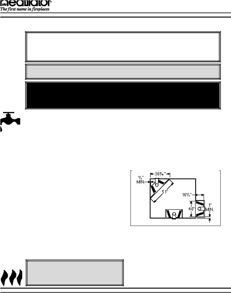
This appliance may be installed along a wall, across a corner or use an exterior chase. The GC150 Series may be installed at a height level with the floor, or it can be raised up from the floor to enhance its visual impact. Figure 1 illustrates a variety of ways the appliance may be located in a room. These appliances are also certified for installation in a bedroom or bed/sitting room in the U.S.
Figure 1
Fireplace Locations and Clearances
D. CLEARANCES
The following clearances to combustibles must be maintained: Minimum clearances to the top standoffs of the unit - 0", floor - 0", back - 1/2", sides - 1/2", top of the hood to ceiling - 30". Minimum clearances to venting are as follows: Horizontal runs require a 3" minimum air space on the top and a 1" minimum air space on the sides and bottom of the vent section. Vertical rise sections require a 1" minimum air space completely around the vent sections.
2-99 |
6 |
21322L |
GC150 SERIES DIRECT VENT GAS APPLIANCE
E. FRAMING THE FIREPLACE
Note: If an optional fan (FK4) or hand held remote control (RC4 or RC5) are to be used, wiring must be done prior to finishing to avoid reconstruction.
Note: The remote wall switch must be wired prior to applying the finishing material in order to avoid reconstruction.
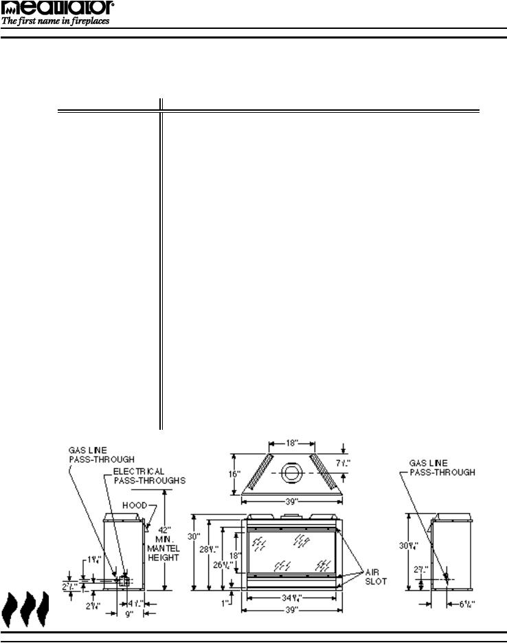
The GC150 Series Gas Appliance will fit a framed opening of 40" w X 161⁄2" d X 301⁄8" h.
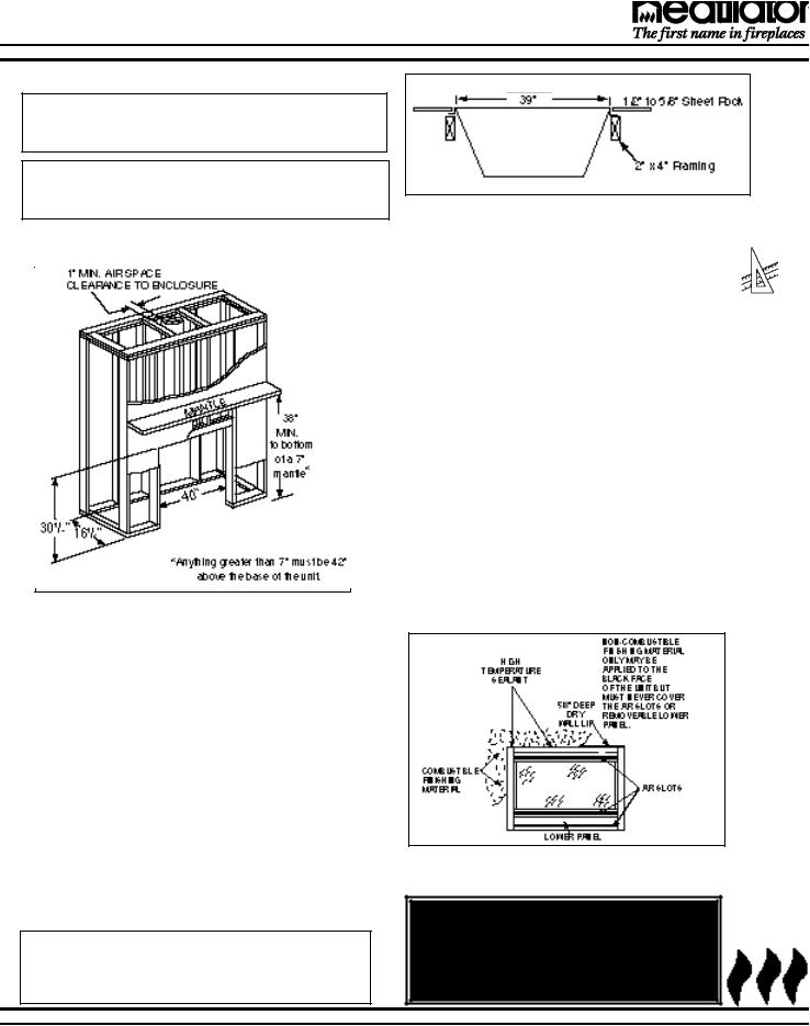
Figure 2 - Framing the Fireplace
Figures 2 and 2a show a typical framing of this fireplace assuming combustible materials are used. All required clearances to combustibles around the fireplace must be adhered to. A 1/2" air clearance must be maintained at the back and sides of the firebox assembly. A minimum of 38” is required to the bottom of a 7” mantle. Anything greater than 7” must be 42” above the base of the unit. Any framing on top of the fireplace must be above the top standoffs. Vent sections for a horizontal run require a 3" minimum air space on top and a 1" minimum air space on the sides and bottom. Vertical rise sections require a 1" minimum air space completely around the vent sections.
Flue outside diameter: 8"
Minimum firestop framing: 10" X10"
Face of header to the center of the firestop spacer (FS6) framing: 87/8"
Note: The outside walls of the home around the fire place should be insulated and finished as one would any other outside wall, while maintaining the 1/2"air clearance around the firebox.
Figure 2a
Framing the Fireplace
F. FINISHING MATERIALS
Only non-combustible materials may be used to cover the black surfaces of the fireplace front.
Combustible Finishing Material. Material made of or surfaced with wood, compressed paper, plant fibers, plastics, or any material capable of igniting and burning, whether flame proofed or not, plastered or unplastered.
Non-combustible Finishing Material. Material which will not ignite and burn. Such materials are those consisting entirely of steel, iron, brick, tile, concrete, slate, glass or plasters, or combination thereof.
High Temperature Sealant Material. Sealants that will withstand high temperatures (300° F+); General Electric RTV103 (Black), or equivalent. Rutland, Inc. Fireplace Mortar #63, or equivalent.
After completing the framing and applying the finishing material (dry wall) over the framing, a non-com- bustible sealant, one-half inch wide maximum, must be used to close off any gaps at the top and sides between the fireplace and facing to prevent cold air leaks. See Figure 3.
Figure 3
Finishing Materials
WARNING!
AIR SLOTS ON THIS APPLIANCE CANNOT, IN ANY WAY, BE COVERED AS IT MAY CREATE A FIRE HAZARD.
12-98 |
7 |
21322K |
GC150 SERIES DIRECT VENT GAS APPLIANCE
V. STEP-BY-STEP INSTALLATION OF
THE FIREPLACE SYSTEM
WARNING!
BEFORE STARTING, DO THE FOLLOWING:
1.WEAR GLOVES AND SAFETY GLASSES FOR PROTECTION.
2.KEEP HAND TOOLS IN GOOD CONDITION. SHARPEN CUTTING EDGES AND MAKE SURE TOOL HANDLES ARE SECURE.
3.ALWAYS MAINTAIN THE MINIMUM AIR SPACE REQUIRED TO THE ENCLOSURE TO PREVENT FIRE.
STEP 1 - Positioning the Firebox |
|
|
|
|
This fireplace may be placed on a smooth combustible or non- |
|
|
|
|
combustible continuous, flat surface. When the appliance is |
|
|
|
|
installed directly on carpeting, tile or other combustible material |
|
|
|
|
other than wood flooring, the appliance shall be installed on a |
|
|
|
|
metal or wood panel extending the full width and depth of the appli- |
|
|
|
|
ance. Slide the unit into position and level the fireplace from side- |
|
|
|
|
to-side and front-to-back. Shim with non-combustible material, |
|
|
|
|
such as sheet metal, as necessary. |
|
|
|
|
Secure the fireplace by bending out the nailing flanges located on |
|
|
|
|
each side of the fireplace and nailing the unit to the framing. See |
A |
|
|
B |
Figure 4. |
|
|
|
|
|
Figure 4 |
|||
STEP 2 - Termination |
|
|||
|
Nailing Flanges |
|||
|
|
|||
Two types of termination are available for this appliance, horizontal and vertical. For vertical termination, skip section A and advance to section B on page 11.
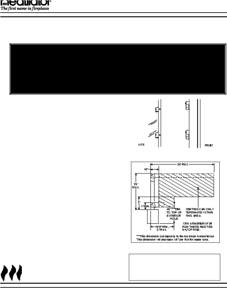
A. Horizontal Termination
Minimum combustible clearances to the vent on a horizontal run is 3" on top and 1" on the bottom and sides. These clearances must be maintained at all times. The maximum horizontal run allowed for venting is 26 feet. The maximum vertical rise allowed for horizontal termination is 25 feet. See Figure 5.
1. Assembling vent sections. Attach either a VE12 (starter elbow), VE16, VE20 or straight vent section (depending upon your specific installation) to the top of the appliance. Secure with the three screws supplied. Use only vent supplied and listed for use with this appliance and the appropriate number of direct vent sections. MAINTAIN MINIMUM CLEARANCES OR GREATER AROUND THE VENT SYSTEM. Do not pack air spaces with insulation or other material.
a. Using elbows. The first elbow used with horizontal termination must be starter elbow 15942. The maximum horizontal distance this vent system may reach is 26'.No more than 3 elbows may be used. A single vertical-to-horizontal elbow is already calculated into the allowable 26' run. Each additional elbow reduces the maximum horizontal distance by three feet. Example, by using three total elbows, the maximum horizontal distance has been reduced to twenty feet (3 - 1 = 2 elbows X 3' = 6'; 26' max. - 6' of elbows = 20' of horizontal run).
Figure 5 - Horizontal Length
Note: The horizontal run of vent must have a 1/4" rise for every 1 ft. of run towards the termination. Never allow the vent to run downward. This could cause high temperatures and may present the possibility of a fire.
1-99 |
8 |
21322L |
GC150 SERIES DIRECT VENT GAS APPLIANCE
b. Amount of venting required. Due to the many different combinations that can be used when constructing venting, the number of vent sections required can only be determined by the installer.
Note: Horizontal runs will require the use of one Vent Support (VS4) for every 3' of vent.
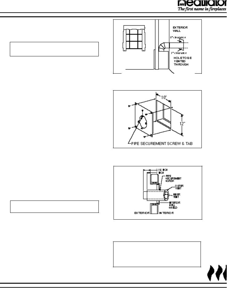
2. Preparing the wall for interior wall shield. A hole measuring 10" wide X 12" high must be cut and framed in the exterior wall where venting will be terminated. If the wall being penetrated is constructed of non-combustible material, i.e. masonry block or concrete, a 9" diameter port is acceptable.
The hole must be positioned so the vent system will have a 1/4" rise for every 12" of run AND be perpendicular to the wall. See Figure 6. The height of the hole must be located to meet all local and national codes and not be easily blocked or obstructed. The minimum height to the top of the exterior wall hole is 45” from the base of the unit. This figure will increase by the length of each vertically positioned vent section added to the venting system.
3. Interior Wall Shield. An interior wall shield must be installed each time the venting system penetrates a wall. This shield has been designed to maintain the minimum clearances needed for the venting system and prevent cold air infiltration.
After the venting hole has been cut and framed, secure an interior wall shield into position with four 1" fasteners, one in each corner. Bend out the tabs located on the inner portion of the wall shield and use a 1/2" screw to secure each tab to the penetrating pipe. See Figure 7. (1/2" screws are used to avoid penetrating the inner pipe.)
Note: Exterior wall thickness must be a minimum of 4" to a maximum of 231⁄2”.
4. Venting through the wall. Horizontal venting must terminate within the shaded area shown in Figure 5 on the previous page. For example, if your vertical rise is the minimum one foot, venting can terminate anywhere between 16 inches and 3 feet.
The last section of vent may require cutting, depending upon wall thickness and appliance location. The end of the vent must penetrate the exterior wall. Cut the pipe so the outer vent section extends past the exterior wall by 1" and the inner vent section extends past the exterior wall by 21⁄2". See Figure 8.
Figure 6
Exterior Wall Hole
Figure 7
Interior Wall Shield
Figure 8
Venting Through the Wall
NOTE: IF THE TERMINATION CAP IS SURROUNDED BY VINYL SIDING OR IS LOCATED BELOW A VINYL SOFFIT, A VINYL SHIELD MUST BE USED TO PREVENT DAMAGE TO THE VINYL.
1-99 |
9 |
21322L |
 Loading...