

Page 1
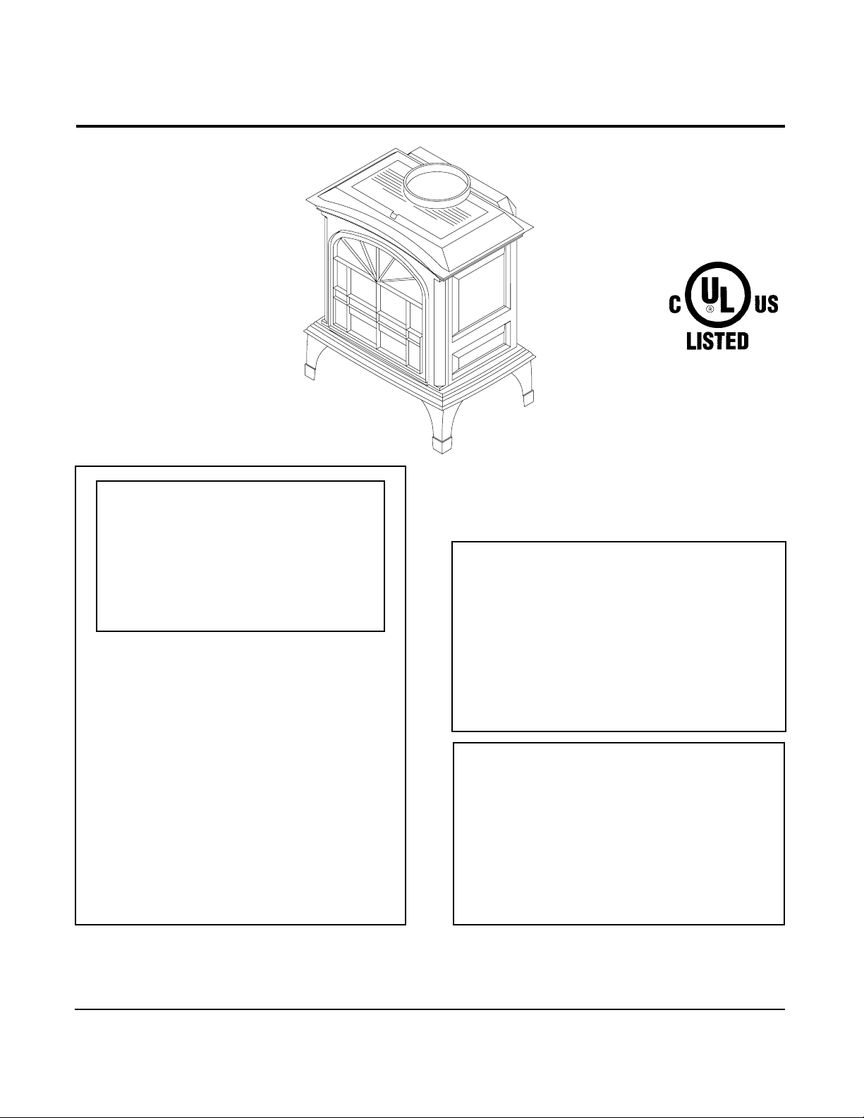
Heat-N-Glo Fireplace
Models:
Townsend I and II
W ARNING: IF THE INFORMATION IN
THESE INSTRUCTIONS IS NOT
FOLLOWED EXACTL Y , A FIRE OR
EXPLOSION MA Y RESUL T CAUSING
PROPERTY DAMAGE, PERSONAL
INJURY, OR DEA TH.
- Do not store or use gasoline or other flammable vapors and liquids in the vicinity of
this or any other appliance.
- What to do if you smell gas
• Do not try to light any appliance.
• Do not touch any electrical switch.
• Do not use any phone in your building.
• Immediately call your gas supplier from a
neighbor's phone. Follow the gas supplier's
instructions.
• If you cannot reach your gas supplier, call
the fire department.
- Installation and service must be performed by a
qualified installer, service agency, or the gas
supplier.
Installers Guide
Underwriters
Laboratories Listed
READ THIS MANUAL BEFORE INSTALLING
OR OPERATING THIS APPLIANCE. THIS
INSTALLERS GUIDE
THE APPLIANCE FOR FUTURE REFERENCE.
WARNING: IMPROPER INSTALLATION, ADJUSTMENT, ALTERATION,
SERVICE OR MAINTENANCE CAN
CAUSE INJURY OR PROPERTY DAMAGE. REFER TO THIS MANUAL. FOR
ASSISTANCE OR ADDITIONAL INFORMATION CONSULT A QUALIFIED
INSTALLER, SERVICE AGENCY, OR
THE GAS SUPPLIER.
1. This appliance may be installed in an
aftermarket, permanently located,
manufactured (mobile) home, where
not prohibited by local codes.
2.This appliance is only for use with the
type of gas indicated on the rating
plate. This appliance is not convertible
for use with other gases, unless a
certified kit is used.
MUST BE LEFT WITH
Printed in U.S.A. Copyright 1998,
Heat-N-Glo, a division of Hearth Technologies Inc.
6665 West Highway 13, Savage, MN 55378
This product is covered by one or more of the following patents: (United States) 4,112,913; 4,408,594; 4,422,426; 4,424,792; 4,520,791; 4,793,322;
4,852,548; 4,875,464; 5,000,162; 5,016,609; 5,076,254 5,191,877; 5,218,953; 5,328,356; 5,429,495; 5,452,708; 5,542,407; 5,613,487; (Australia) 543790; 586383;
(Canada) 1,123,296; 1,297,746; 2,195,264; (Mexico) 97-0457; (New Zealand) 200265; or other U.S. and foreign patents pending.
Please contact your Heat-N-Glo dealer for any
questions or concerns. For the number of your
Heat-N-Glo dealer, please call 612-890-8367.
402-982-A 11/98
nearest
Page 2
SAFETY AND WARNING INFORMATION
READ
and
!
FAILURE TO FOLLOW
hazard and will void the warranty.
UNDERSTAND
all instructions carefully before starting the installation.
these installation instructions may result in a possible fire
Prior to the first firing of the fireplace,
!
Owners Guide
DO NOT USE
!
qualified service technician to inspect the unit and to replace any part of the control
system and any gas control which has been underwater.
THIS UNIT IS NOT FOR USE WITH SOLID FUEL.
!
Installation and repair should be
!
appliance and venting system should be
annually by a professional service person. More frequent cleaning may be required
due to excessive lint from carpeting, bedding material, etc. It is
unit’s control compartment, burners, and circulating air passageways
CLEAN
Always
!
other flammable vapors and liquids.
NEVER OBSTRUCT
!
appliance
Due to the high temperature, the appliance should be
!
and away from furniture and draperies. Clothing or flammable material
BE PLACED
Children and adults should be ALERTED to the hazards of high surface temperature
!
and should STAY AWAY to avoid burns or clothing ignition. Young children should be
CAREFULLY SUPERVISED when they are in the same room as the appliance.
These units
!
section of the
.
this appliance if any part has been under water. Immediately
to provide for adequate combustion and ventilation air.
KEEP
the appliance clear and free from combustible materials, gasoline, and
CLEAR
on or near the appliance.
MUST
Installers Guide. NO OTHER
the flow of combustion and ventilation air. Keep the front of the
of all obstacles and materials for sevicing and proper operations.
use one of the vent systems described in the Installing the Fireplace
READ
the Using Your Fireplace section of the
PERFORMED
INSPECTED
vent systems or components
by a qualified service person. The
before initial use and at least
IMPERATIVE
BE KEPT
LOCATED
out of traffic areas
SHOULD NOT
MAY BE USED
CALL
that the
a
.
This gas fireplace and vent assembly
!
MUST NEVER
appliance. Each gas appliance
systems are
INSPECT
!
interfering with the air flow.
The glass door assembly
!
MUST
be in place on the fireplace before the unit can be placed into safe operation.
DO NOT OPERATE
!
Replacement of the glass door should be performed by a licensed or qualified service
person.
The glass door assembly
!
by the gas fireplace manufacturer.
DO NOT USE
!
clean the glass door when it is hot.
Turn off the gas before servicing this appliance. It is recommended that a
qualified service technician perform an appliance check-up at the beginning
!
of each heating season.
Any safety screen or guard removed for servicing must be replaced before operating
!
this appliance.
be attached to a chimney serving a separate solid fuel burning
PROHIBITED
the external vent cap on a regular basis to make sure that no debris is
DO NOT
strike or slam the glass door.
abrasive cleaners on the glass door assembly.
.
MUST
this appliance with the glass door removed, cracked, or broken.
SHALL ONLY
MUST
be vented directly to the outside and
MUST USE
be in place and sealed, and the trim door assembly
NO SUBSTITUTE
a separate vent system. Common vent
be replaced as a complete unit, as supplied
material may be used.
DO NOT ATTEMPT
to
i
Page 3

Safety and Warning Information ........................... i
Section 1: Approvals and Codes.........................1
Approval Listings and Codes ..................................... 1
Appliance Certification ...............................................1
Installation Codes ......................................................1
High Altitude Installations........................................... 1
Section 2: Getting Started .................................... 2
Introducing the Heat-N-Glo Direct Vent Gas Stoves..... 2
Pre-installation Preparation........................................ 2
Section 3: Installing the Stove ............................. 5
Step 1 Locating the Stove ......................................5
Step 2 Setting Up the Stove ................................... 6
Step 3 Installing the Vent System ........................... 7
A. Vent System Approvals........................... 7
B. Installing V ent Components................... 14
C. V ent T ermination.................................... 19
Step 4 The Gas Control System ..........................24
Step 5 The Gas Supply Line................................. 24
Step 6 Gas Pressure Requirements .................... 25
Step 7 Wiring the Stove........................................ 26
Step 8 Finishing .................................................... 27
Step 9 Installing Logs and Ember Material ...........27
Positioning the Logs .................................. 27
Placing the Ember Material .......................27
Step 10 Before Lighting the Stove .......................... 28
Step 11 Lighting the Stove......................................28
After the Installation...................................28
Table of Contents
Section 4: Maintenance and Servicing..............29
Section 5: Replacement Parts
and Accessories ............................... 31
Replacement Parts .................................................. 31
Accessories .......................................................... 35
i i
Page 4
1
Approvals and
Regulations
Approval Listings
and Codes
MODEL LABORATORY TYPE STANDARD
Townsend I & II Underwriters Vented Gas ANSI
Laboratories
Installation Codes
Installation must conform to local codes. In the absence of local codes installation
must conform with the current National Fuel Gas Code ANSI Z223.1 (in the United
States) or with the current installation code CAN/CGA - B149 (in Canada).
The appliance when installed must be electrically grounded in accordance with
local codes; in absence of local codes, with the current National Electric Code
ANSI/ NFPA NO. 70 (in the United States) or with the current CSA C22.1 Canadian Electric Code (in Canada).
High Altitude Installations
These units are tested and approved for elevations from 0-2000 feet. (In the United
States) and 0-4500 feet (in Canada).
Appliance Certification
The Heat-N-Glo gas stove models discussed in this
Installers Guide
standards and listed by the applicable laboratories.
Fireplace Heater
have been tested to certification
CERTIFICATION
Z21.88• CSA2.33
When installing this unit at an elevation above 2000 feet, (in United States) it may
be necessary to decrease the input rating by changing the existing burner orifice
to a smaller size. Input should be reduced 4 percent for each 1000 feet above sea
level. Check with your local gas company for help in determining the proper orifice size.
When installing this unit at an elevation above 4500 feet (in Canada), check with
local authorities.
Consult your local gas company for assistance in determining the proper orifice
for location.
1
Page 5

Introducing the
Heat-N-Glo
Direct Vent
Gas Stoves
Pre-installation
Preparation
Heat-N-Glo direct vent gas stoves are designed to
operate with all combustion air siphoned from outside
of the building and all exhaust gases expelled to the
outside.
The information contained in this
unless noted otherwise, applies to all models and gas
control systems.
Gas stove diagrams, including the dimensions, are
shown in this section.
This gas stove and its components are tested and
safe when installed in accordance with this
Guide
. Report to your dealer any parts damaged in
shipment, particularly the condition of the glass. Do
not install any unit with damaged, incomplete, or
substitute parts.
The vent system components and trim doors are
shipped in separate packages. The gas logs are
packaged separately and must be field installed.
Read all of the instructions before starting the
installation. Follow these instructions carefully
during the installation to ensure maximum safety
and benefit. Failure to follow these instructions
will void the owner’s warranty and may present a
fire hazard.
Installers Guide
Installers
,
2
Getting
Started
The Heat-N-Glo Warranty will be voided by, and HeatN-Glo disclaims any responsibility for, the following
actions:
• Installation of any damaged stove or vent system
component.
• Modification of the stove or vent system.
• Installation other than as instructed by Heat-N-Glo.
• Improper positioning of the gas logs or the glass
door.
• Installation and/or use of any component part not
manufactured and approved by Heat-N-Glo, not
withstanding any independent testing laboratory or
other party approval of such component part or
accessory .
ANY SUCH ACTION MAY POSSIBL Y CAUSE A
FIRE HAZARD.
2
Page 6
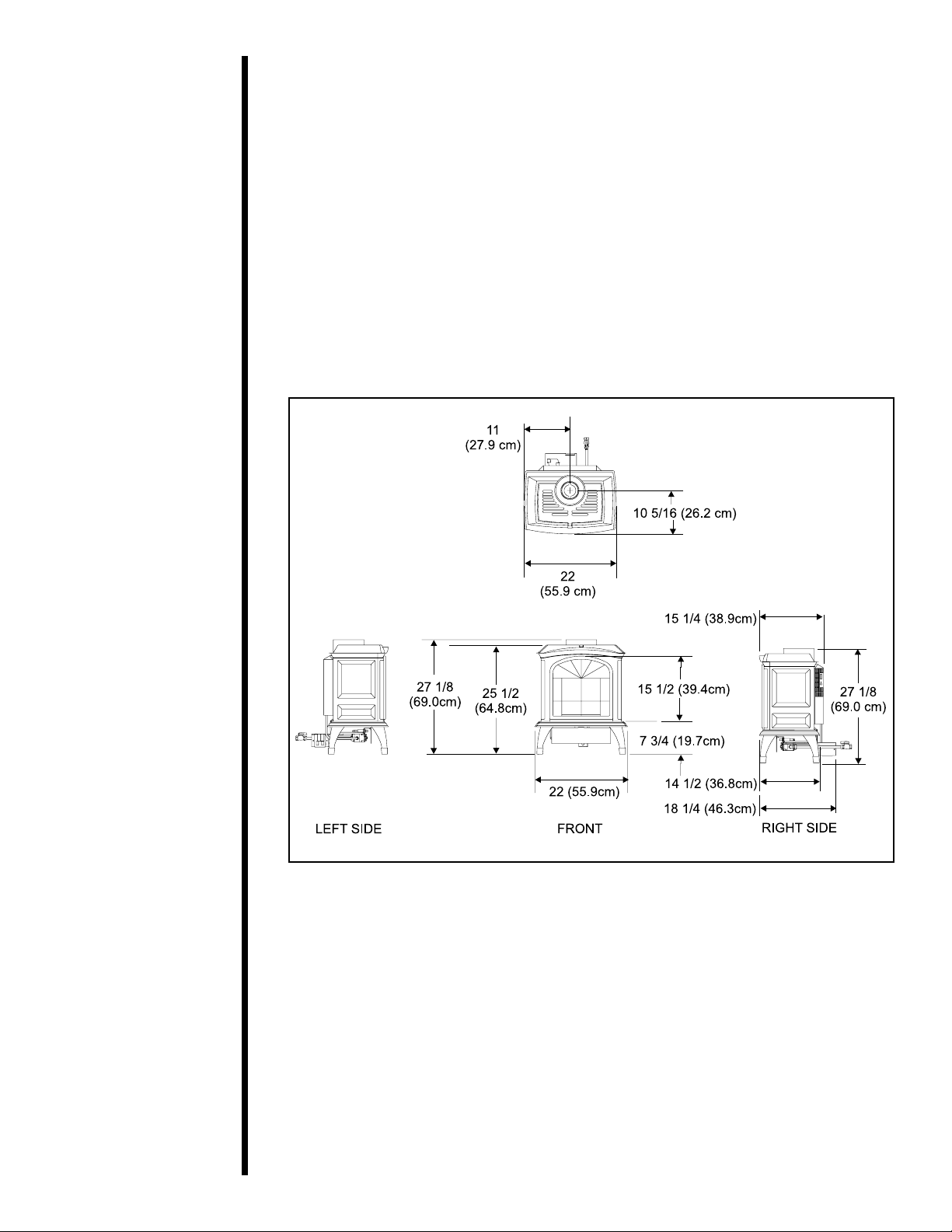
When planning a stove installation, it’s necessary to determine:
• Where the unit is to be installed.
• The vent system configuration to be used.
• Gas supply piping.
• Electrical wiring.
• Framing and finishing details.
• Whether optional accessories—devices such as a fan, wall switch, or remote
control—are desired.
If the stove is to be installed on carpeting or tile, or on any combustible material
other than wood flooring, the stove should be installed on a metal or wood panel
that extends the full width and depth of the stove.
Figure 1. Diagram of the T OWNSEND-I
3
Page 7
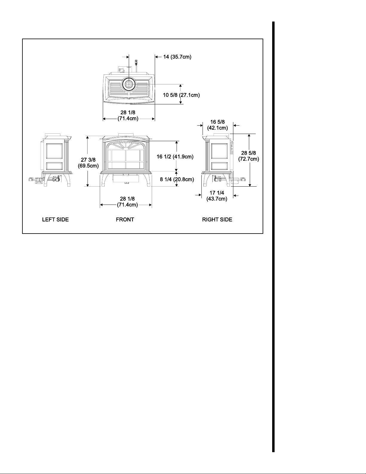
Figure 2. Diagram of the T OWNSEND-II
4
Page 8
3
Installing
the Stove
Step 1
Locating the
Stove
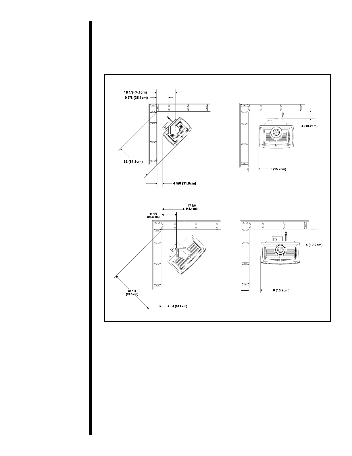
The diagram below shows space and clearance
requirements for locating the stove within a room.
TOWNSEND I
TOWNSEND II
Figure 3. Stove Dimensions, Locations, and Space Requirements
5
Page 9
Clearance Requirements
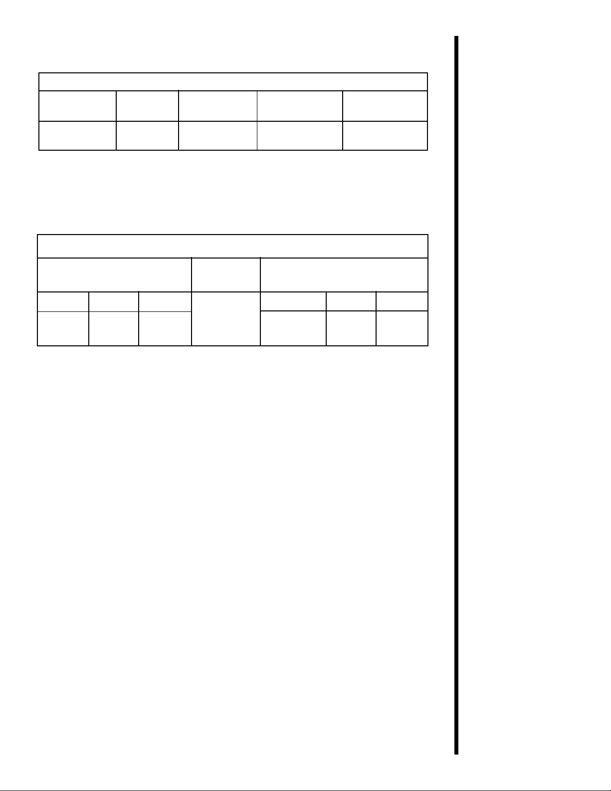
Minimum Clearances from the Fireplace to Combustible Materials
Glass Sides of Top of
Front Floor Rear Fireplace Fireplace
36 inches 0 4 inches 6 inches 55 inches
(914mm) (100mm) (150mm) (134cm)
The minimum clearance to a perpendicular wall
extending past the face of the fireplace is 6 inches
(150mm).
The back of the fireplace may NOT be recessed
into combustible construction.
Minimum Clearances from the Vent Pipe to Combustible Materials
For Vertical
For Horizontal Sections Sections At Wall Firestops
Top Bottom Sides Top Bottom Sides
3 inches 1 inch 1 inch 1 inch 2 1/2 inches 1/2 inch 1 inch
(75mm) (25mm) (25mm) (25mm) (63.7mm) (13mm) (25mm)
Step 2
Setting up the
Stove
For minimum clearances, see the direct vent
termination clearance diagrams on pages 21 and 23
in this manual.
Removal of the cast front surround:
1. Remove the two small bolts from underneath the
front of the cast bottom. These bolts can be
discarded.
2. Remove the screw from underneath the front of
the grille.
3. The cast front surround can now be removed by
tilting its top towards the front and lifting it out of
the stove.
4. When the cast front surround is replaced, it can
be held in place with just the one screw in the
top, underneath the grille.
Removal of glass:
1. Remove the Cast Front Surround.
2. For TOWNSEND-I: Remove the six screws
securing the glass and remove the glass.
3. For TOWNSEND-II: Remove the four screws
located at the top, tilt the glass slightly toward
you and pull up and away from the unit.
To replace the glass reverse these steps.
6
Page 10
Step 3
Installing the
Vent System
A. Vent System Approvals
This model is approved for 4”/6 5/8” SL D-Series
vent pipe components and terminations. Approved
vent systems components are are labeled for
identification. NO OTHER VENT SYSTEMS OR
COMPONENTS MA Y BE USED. Detailed installation
instructions are inclued with each vent termination
kit and should be used in conjuction with this manual.
WARNING:
!
A minimum 3 foot length of straight vent
pipe MUST be attached to the unit’s
starting collars for all vent systems.
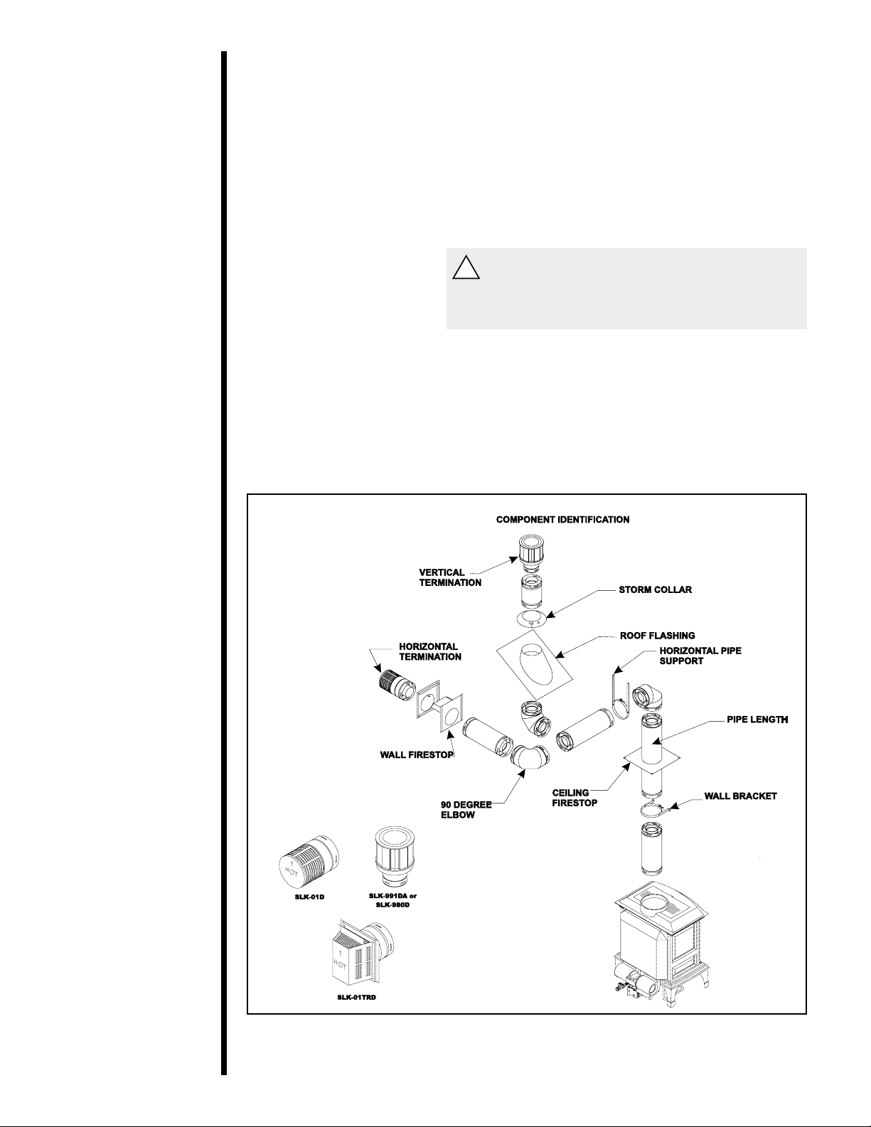
Identifying Vent Components
The vent systems installed on this gas stove may
include one, two, or three 90°
The relationships of vertical rise to horizontal run in
vent configurations using 90° elbows MUST BE
strictly adhered to. The rise to run relationships are
shown in the vent drawings and tables. Refer to the
diagrams on the next several pages.
elbow assemblies.
Vent System Termination Kits
7
Figure 4. Vent Components and Terminations
Page 11
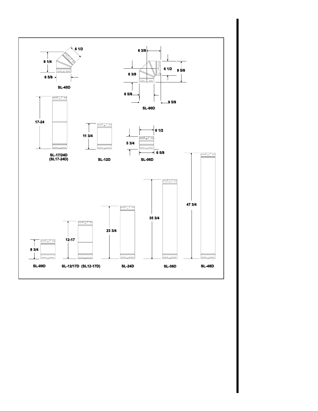
Figure 5. SL D-Series Direct V ent Component Specifications
(4-inch inner pipe/6 5/8-inch outer pipe)
8
Page 12
Straight V ertical Vent System
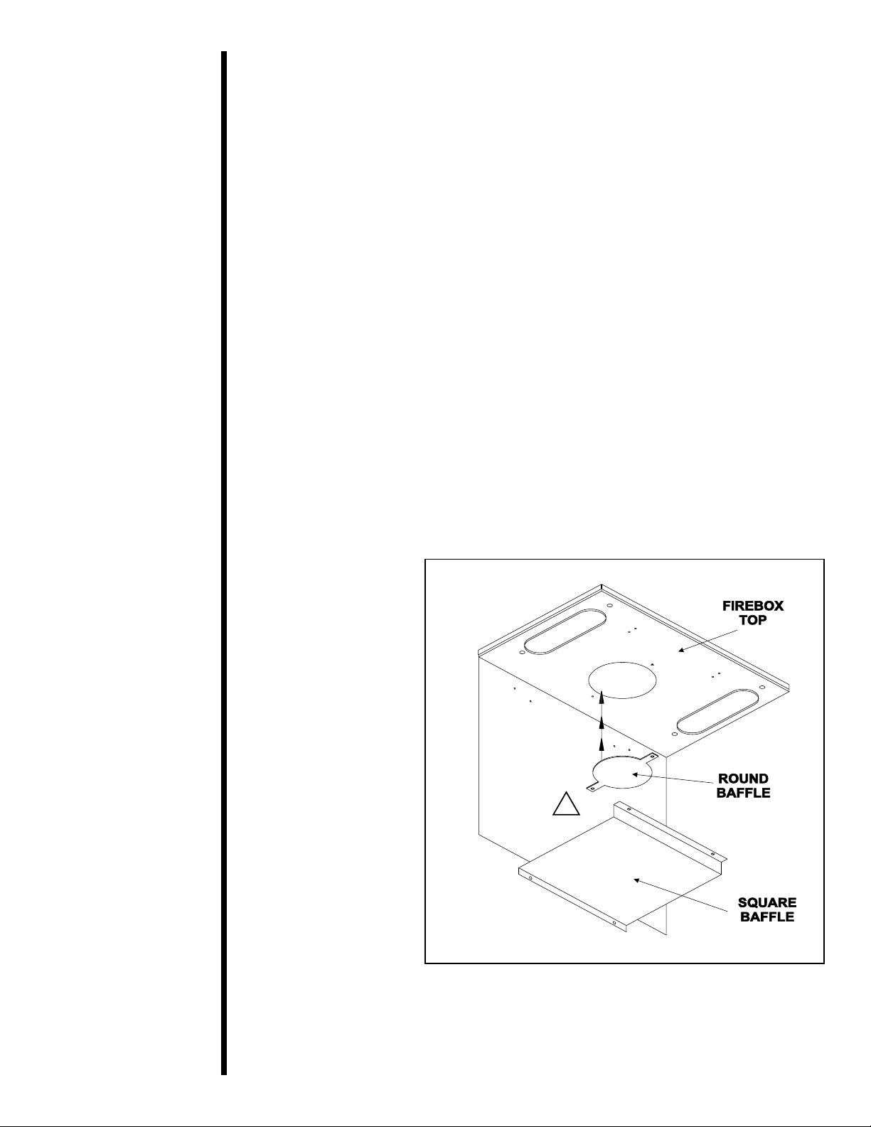
When a vertical run of 12 feet and higher is attached
directly to the top of the stoves, further baffling is
necessary to maintain high efficiency. A round baffle
with two tabs on each side is included in the manual bag
assembly. To install the round baffle follow these steps:
1. Remove the front of the casting. Refer to cast front removal on page 6.
2. Remove the glass assembly. Refer to glass removal
on page 6.
3. Remove logs and set aside.
4. Disassemble the square baffle by unfastening four
screws located inside top of the firebox. See Figure 6.
5. Unfasten the two screws on the existing round baffle,
and replace it with the new round baffle. Note: The new
round baffle is bigger than the existing round baffle already on the unit.
6. Re-install the square baffle removed in Step 4.
!
Figure 6
9
Page 13

VERTICAL VENT
V (FT)
3 (915mm) MIN.
40 (12.19m) MAX.
Figure 7. Straight Vertical Vent System
10
Page 14

TOWNSEND I
VENTING WITH ONE (1) 90o ELBOW
VENTING WITH ONE (1) 90o ELBOW
TOWNSEND II
V (FT) H (FT)
2’MIN.(610mm) 2’MAX.(610mm)
3’MIN.(914mm) 3’MAX.(914mm)
4’MIN.(1.2m) 4’MAX.(1.2m)
18’ MIN.(5.4m) 18’ MAX.(5.4m)
V + H = 40’ MAX.(12.19m)
H = 18’ MAX.(5.4m)
V (FT) H (FT)
3’MIN.(610mm) 2’MAX.(610mm)
4’MIN.(1.2m) 2.5’ MAX.(1762mm)
18’ MIN.(5.4m) 12’ MAX.(3.66m)
V + H = 40’ MAX.(12.19m)
H = 12’ MAX.(3.66m)
11
NOTE: Optional Kit #970D
can be used for this type
of installation on model
Townsend I.
Figure 8. Vent System with One 90° Elbow
Page 15

VENTING WITH TWO (2) 90o ELBOWS
TOWNSEND I
TOWNSEND II
VENTING WITH TWO (2) 90o ELBOWS
V (FT) H (FT)
3’ MIN.(914mm) 3’ MAX.(914mm)
4’ MIN.(1.2m) 4’ MAX.(1.2m)
18’ MIN.(5.4m) 18’ MAX.(5.4m)
V + V1 + H = 40’ MAX.(12.19m)
H = 18’ MAX.(5.4m)
TOWNSEND I and TOWNSEND II
VENTING WITH TWO (2) 90o ELBOWS
V (FT) H (FT) V1 (FT)
.5’ MIN. (152mm) 4’ MAX. (1.2m) 8’ MIN. (2.4m)
V+V1 = 36’ MAX. (10.97m)
V (FT) H (FT)
3’MIN.(610mm) 2’ MAX.(610mm)
4’MIN.(1.2m) 2.5’ MAX.(1762mm)
18’ MIN.(5.4m) 12’ MAX.(3.66m)
V + V1 + H = 40’ MAX.(12.19m)
H = 12’ MAX.(3.66m)
Figure 9. Vent System with Two 90° Elbows
12
Page 16

VENTING WITH THREE (3) 90o ELBOWS
TOWNSEND I
TOWNSEND II
VENTING WITH THREE (3) 90o ELBOWS
V (FT) H (FT)
3’ MIN.(914mm) 3’ MAX.(914mm)
4’ MIN.(1.2m) 4’ MAX.(1.2m)
18’ MIN.(5.4m) 18’ MAX.(5.4m)
V+V1+H+H1 = 40’ MAX.(12.19m)
H+H
= 18’ MAX.(5.4m)
1
V (FT) H (FT)
3’MIN.(610mm) 2’ MAX.(610mm)
4’MIN.(1.2m) 2.5’ MAX.(1762mm)
18’ MIN.(5.4m) 12’ MAX.(3.66m)
V+V1+H+H1 = 40’ MAX.(12.19m)
H+H
= 12’ MAX.(3.66m)
1
13
Figure 10. Vent System with three 90° elbows
Page 17

B. Installing V ent Components
Before starting installation of vent kits, the installer
should read the Gas Stove Instructions and the Vent
Kit Instructions to ensure that the proper system has
been selected for the installation.
Determine the exact position of the stove so the vent
pipe is centered (if possible) between two building
framing members. This will avoid any extra framing.
Using a level, make sure the stove is properly
positioned and squared. Minimum clearances to walls
and ceilings must be maintained.
Vent terminals should not be recessed into a wall.
Consult your local Building Code Regulations before
beginning the installation.
WARNING
!
THIS GAS STOVE AND VENT ASSEMBLY
MUST BE VENTED DIRECTLY T O THE
OUTSIDE AND MUST NEVER BE
A TTACHED TO A CHIMNEY SER VING A
SEP ARATE SOLID FUEL BURNING
APPLIANCE. EACH GAS APPLIANCE
MUST USE A SEPARATE VENT SYSTEMCOMMON VENT SYSTEMS ARE
PROHIBITED.
1. Attach the First Vent Component to the
Starting Collars
To attach the first vent component to the starting
collars of the fireplace:
• Apply a 3/8 inch (9.5mm) bead of stove cement
around the 4 inch (100mm) fireplace starting collar.
• Make sure that the fireplace rope gasket supplied
with the fireplace seals between the first vent
component and the outer fireplace wrap.
• Lock the vent components into place by sliding the
concentric pipe sections with four (4) equally
spaced interior beads into the fireplace collar or
previously installed component end with four (4)
equally spaced indented sections.
• When the internal beads of each outer pipe line up,
rotate the pipe section clockwise about one-quarter
(1/4) turn. The vent pipe is now locked together .
14
Page 18

1. Apply the stove
cement.
2. Line up the internal
beads and rotate the
pipe sections clockwise until locked.
3. Lock the vent components into place.
Figure 11. Attaching the First Vent Component to
the Starting Collars
WARNING
A 3/8 INCH (9.5 mm) BEAD OF STOVE
CEMENT MUST BE PLACED AROUND
THE STOVE ST ARTING COLLAR
BEFORE ATTACHING THE FIRST VENT
COMPONENT. FAILURE TO SEAL THIS
JOINT MA Y CAUSE THE ST OVE T O
OPERA TE IMPROPERLY . SEE THE
DIAGRAM .
2. Continue Adding Vent Components
To continue adding vent components in accordance
with the pre-planned vent system configuration:
• Ensure that each succeeding vent component is
securely fitted and locked into the preceding
component in the vent system.
90° elbows may be installed and rotated to any point
around the preceding component’s vertical axis. If an
elbow does not end up in a locked position with the
preceding component, attach with a minimum of three
(3) sheet metal screws.
15
Page 19

Continue adding vent
components, locking
each succeeding
component into place.
Figure 12. Adding Venting Components
3. Install Support Brackets
For Horizontal Runs - The vent system must be
supported every 5 feet (1.5m) of horizontal run by a
horizontal pipe support.
To install support brackets for horizontal runs:
• Place the pipe supports around the vent pipe.
Use wall brackets to
support vertical runs
every 8 feet (2.4m)
above the stove vent
outlet.
• Nail the pipe supports to the framing members.
For Vertical Runs - The vent system must be
supported every 8 feet (2.4m) above the stove vent
outlet by wall brackets.
To install support brackets for vertical runs:
• Attach wall brackets to the vent pipe and secure the wall
bracket to the framing members with nails or screws.
Figure 13. Installing Support Brackets
16
Page 20

4. Install Firestops
For Horizontal Runs - Firestops are REQUIRED on
both sides of a combustible wall through which the
vent passes.
NOTE
1. Cut the 10 in. x 10 in.
(254 x 254mm) hole.
Model SLK-01TRD does not need an exterior
firestop on an exterior combustible wall.
To install firestops for horizontal runs that pass
through either interior or exterior walls:
• Cut a 10 in. x 10.in (254mm X 254mm) hole
through the wall. The center of the hole is 1-inch
(25.4mm) above the center of the horizontal vent
pipe.
• Position the firestops on both sides of the hole
previously cut and secure the firestops with nails or
screws.
• The heat shields of the firestops MUST BE placed
towards the top of the hole.
• Continue the vent run through the firestops.
17
Figure 14. 10 in. X 10 in. Hole and Vent Pipe
Page 21

1. Position the firestops.
2. Place the heat shield
to the top.
3. Continue the vent run.
Figure 15. Heat Shield, Interior and Exterior
Firestops
For Vertical Runs - One ceiling firestop is
REQUIRED at the hole in each ceiling through which
the vent passes.
To install firestops for vertical runs that pass through
ceilings:
1. Cut the 10” x 10” hole.
2. Add the new framing
members.
• Position a plumb bob directly over the center of the
vertical vent component.
• Mark the ceiling to establish the centerpoint of the
vent.
• Drill a hole or drive a nail through this centerpoint.
• Check the floor above for any obstructions, such as
wiring or plumbing runs.
• Reposition the stove and vent system, if necessary,
to accommodate the ceiling joists and/or obstructions.
• Cut an 10” x 10” (254mm X 254mm) hole through
the ceiling, using the centerpoint previously marked.
• Frame the hole with framing lumber the same size
as the ceiling joists.
10 in.
(254mm)
10 in.
(254mm)
Figure 16. 10” x 10” Hole and New Framing
Members
18
Page 22

This shows a ceiling
installation.
This shows an attic
installation.
If the area above the ceiling is NOT an attic,
position and secure the ceiling firestop on the
ceiling side of the previously cut and framed hole.
Figure 17. Ceiling Firestop (Ceiling Side)
If the area above the ceiling IS an attic, position and
secure the firestop on top of the previously framed
hole.
1. Keep insulation away
from the vent pipe at
least 1 inch (25 mm).
Figure 18.Attic Firestop
C. Vent Termination
For Horizontal Terminations - To attach and
secure the termination to the last section of
horizontal vent:
• Rotate and interlock the ends as described at
the beginning of the Installing Vent Components
section.
• The termination kit should pass through the wall
firestops from the exterior of the building.
19
• Adjust the termination cap to its final exterior
position on the building.
Page 23

For round cap
termination:
1. Secure the vent pipe,
using the exterior
pipelock hole on the
round flange of the
wall firestop.
WARNING: THE TERMINATION CAP
!
MUST BE POSITIONED SO THA T THE
ARROW IS POINTING UP.
For roundcap termination kits:
• Use the exterior pipelock hole provided on the
round flange of the wall firestop to secure the
vent pipe in place.
For trapezoidal cap termination kits:
• Using screws, secure the cap to the exterior wall
through the flanges built into the cap.
• Use a high-temperature sealant or fiberglass
rope gasket to seal between the vent pipe and
exterior firestop.
For trapezoidal
termination:
1. Screw the cap to the
exterior wall through
the flanges in the cap.
2. Seal the joint between the pipe and
the exterior firestop.
Figure 19. Round & Trapezoid Termination Caps
WARNING: THE BOTTOM OF THE VENT
!
TERMINATION CAP MUST BE A MINIMUM OF 12
INCHES (305MM) ABOVE GROUND LEVEL (GRADE).
THE TOP OF THE CAP MUST BE A MINIMUM OF 18
INCHES (457MM) BELOW COMBUSTIBLE MA TERIAL,
SUCH AS A DECK, AND THE SIDE OF THE CAP MUST
BE A MINIMUM OF 6 INCHES (152MM) A W AY FROM A
PARALLEL OUTSIDE WALL. VENTING TERMINALS
SHALL NOT BE RECESSED INTO A W ALL OR SIDING.
SEE THE FOLLOWING DIAGRAM FOR VENT
TERMINATION CLEARANCES.
20
Page 24

V =VENT TERMINAL
4
4
4
23
23
23
=AREA WHERE TERMINAL IS NOT PERMITTED
X =AIR SUPPLY INLET
A = 12" clearances above grade, veranda, porch, deck or balcony
B = 12" clearances to window or door that may be opened
C = 9" (U.S.A.) clearance to permanently closed window
12" (Canada)
*D = 18" vertical clearance to ventilated soffit located above the
terminal within a horizontal distance of 2 feet (60 cm)
from the center-line of the terminal
*E = 18" clearance to unventilated soffit
F = 9" clearance to outside corner
G = 6" clearance to inside corner
H = 3 ft. (Canada) not to be installed above a gas meter/regulator assembly
within 3 feet (90 cm) horizontally from the center-line of
the regulator
I = 3 ft. (U.S.A.) clearance to service regulator vent outlet
6 ft. (Canada)
J = 9" (U.S.A.) clearance to non-mechanical air supply inlet to building
12" (Canada) or the combustion air inlet to any other appliance
K = 3 ft. (U.S.A.) clearance to a mechanical air supply inlet
6 ft. (Canada)
**L = 7 ft. clearance above paved sidewalk or a paved driveway
located on public property
***M = 18" clearance under veranda, porch, deck or balcony
* 30” minimum for vinyl clad soffits.
** a vent shall not terminate directly above a sidewalk or paved driveway which is
located between two single family dwellings and serves both dwellings.
*** only permitted if veranda, porch, deck or balcony is fully open on a minimum of
2 sides beneath the floor.
NOTE: Local Codes or Regulations may require different clearances.
Figure 20.Vent Termination Minimum Clearances
CAUTION
IF EXTERIOR W ALLS ARE FINISHED WITH VINYL
SIDING, IT IS NECESSARY TO INSTALL THE
VINYL PROTECTOR KIT (VPK-DV) T O THE T OP OF
21
THE EXTERIOR FIRESTOP (FOR ALL ROUND
TERMINA TION CAPS).
Page 25

For Vertical Terminations - To locate the vent
and install the vent sections:
• Locate and mark the vent centerpoint on the
underside of the roof, and drive a nail through the
centerpoint.
• Make the outline of the roof hole around the
centerpoint nail.
• The size of the roof hole framing dimensions
depend on the pitch of the roof. There MUST BE
a 1-inch (25.4 mm) clearance from the vertical
vent pipe to combustible materials.
• Mark the roof hole accordingly.
• Cover the opening of the installed vent pipes.
• Cut and frame the roof hole.
• Use framing lumber the same size as the roof
rafters and install the frame securely . Flashing
anchored to the frame must withstand heavy
winds.
• Continue to install concentric vent sections up
through the roof hole (for inside vent installations)
or up past the roof line until you reach the appropriate distance above the roof (for outside terminations).
NOTE
WARNING
!
MAJOR U.S. BUILDING CODES
SPECIFY MINIMUM CHIMNEY AND/OR
VENT HEIGHT ABOVE THE ROOF T OP.
THESE MINIMUM HEIGHTS ARE
NECESSARY IN THE INTEREST OF
SAFETY. SEE THE FOLLOWING
DIAGRAM FOR MINIMUM HEIGHTS,
PROVIDED THE TERMINA TION CAP IS
A T LEAST TWO (2) FEET FROM A
VERTICAL W ALL AND 2-FEET BELOW A
HORIZONT AL OVERHANG.
This also pertains to vertical vent systems installed
on the outside of the building.
22
Page 26

1. Attach the flashing
and apply sealant
around the edges of
the flashing base.
2. Attach the storm
collar over the flashing joint and apply
sealant between the
storm collar and
vertical pipe.
To seal the roof hole, and to divert rain and snow from
the vent system:
• Attach a flashing to the roof using nails, and use a
non-hardening mastic around the edges of the
flashing base where it meets the roof.
• Attach a storm collar over the flashing joint to form
a water-tight seal. Place non-hardening mastic
around the joint, between the storm collar and the
vertical pipe.
• Slide the termination cap over the end of the vent
pipe and rotate the pipe clockwise 1/4 turn.
TERMINATION
CAP
23
Roof Pitch H (min.) ft.
flat to 6/12 1.0
6/12 to 7/12 1.25
over 7/12 to 8/12 1.5
over 8/12 to 9/12 2.0
over 9/12 to 10/12 2.5
over 10/12 to 1 1/12 3.25
over 1 1/12 to 12/12 4.0
over 12/12 to 14/12 5.0
over 14/12 to 16/12 6.0
over 16/12 to 18/12 7.0
over 18/12 to 20/12 7.5
over 20/12 to 21/12 8.0
Figure 21. Minimum Height from Roof to Lowest
Discharge Opening
Page 27

Step 4
The Gas
Control System
WARNING: THIS UNIT IS NOT FOR USE
!
WITH SOLID FUEL.
Standing Pilot Ignition System
This system includes millivolt control valve, standing pilot,
thermopile/thermocouple flame sensor, and piezo ignitor .
WARNING: 110-120 VAC MUST NEVER
!
BE CONNECTED TO A CONTROL VALVE
IN A MILLIVOLT SYSTEM.
Step 5
The Gas
Supply Line
Figure 22. Gas Controls Systems
NOTE: Have the gas supply line installed by a
qualified service technician in accordance with all
building regulations.
NOTE: Before the first firing of the stove, the gas
supply line should be purged of any trapped air.
NOTE: Consult local building regulations to
properly size the gas supply line leading to the
1/2 inch (13mm) hook-up at the unit.
This gas fireplace is designed to accept a 1/2 inch
(13 mm) gas supply line.
To install the gas supply line:
• A listed 1/2 inch (13 mm) manual shut-of f valve and
a listed flexible gas connector are connected to the
1/2 inch (13 mm) inlet of the control valve.
• A 1/8 inch (3 mm) N.P.T. plugged tapping, accessible
for test gauge connection, should be provided for in
the gas supply line leading to the unit’s shut-off valve.
• Locate the manaul shut-off valve at the rear of the stove.
• Connect the gas supply line to the shut-off valve.
• When attaching the pipe, support the control so that
the lines are not bent or torn.
• After the gas line installation is complete, use a soap
solution to carefully check all gas connections for leaks.
WARNING: DO NOT USE AN OPEN
!
FLAME TO CHECK FOR GAS LEAKS.
24
Page 28

Figure 23 GAS SUPPLY CONNECTION
Step 6
Gas Pressure
Requirements
Pressure requirements for Heat-N-Glo gas stoves
are shown in the table below.
Pressure Natural Gas Propane
Minimum 5.0 inches 1 1.0 inches
Inlet Pressure w. c. w. c.
Maximum Inlet 14.0 inches 14.0 inches
Gas Pressure w.c . w. c.
Manifold 3.5 inches 10.0 inches
Pressure w. c. w .c.
A one-eighth (1/8) inch (3 mm) N.P.T. plugged tapping
is provided on the outlet side of the gas control for a
test gauge connection to measure the manifold
pressure. To measure inlet pressure, provisions must
be made to attach a test gauge to a one-eighth (1/8)
inch (3 mm) N.P.T . plugged tapping immediately
upstream of the gas supply connection to the
fireplace. On some models there may be a tap for the
manifold and inlet pressure on the face of the valve.
Use a small flat blade screwdriver to crack open the
screw in the center of the tap. Position a rubber hose
over the tap to obtain the pressure reading.
25
The fireplace and its individual shut-off valve must
be disconnected from the gas supply piping system
during any pressure testing of the system at test
pressures in excess of one-half (1/2) psig (3.5 kPa).
The fireplace must be isolated from the gas supply
piping system by closing its individual shut-off valve
during any pressure testing of the gas supply piping
system at test pressures equal to or less than onehalf (1/2) psig (3.5 kPa).
Page 29

Step 7
Wiring the
Stove
NOTE: Electrical wiring must be installed by a
competent electrician.
For Standing Pilot Ignition Wiring
Appliance Requirements
• This appliance DOES NOT require 110-120 VAC
to operate.
WARNING: DO NOT CONNECT 110-120
!
V AC TO THE GAS CONTROL VALVE OR
THE APPLIANCE WILL MALFUNCTION
AND THE V ALVE WILL BE DESTROYED.
Optional Accessories
Optional fan and remote control kits require that 1 10120 VAC be wired to the factory installed junction
box before the stove is permanently installed.
Remote Wall Switch
Position the remote wall switch in the desired
position on a wall. Run a maximum of 25 feet (7.8m)
or less length of 18 A.W.G. minimum wire and
connect it to the stove ON/OFF switch pigtails.
WARNING: DO NOT CONNECT 110-120 VAC
!
TO THE REMOTE WALL SWITCH OR THE
CONTROL VALVE WILL BE DESTROYED.
CAUTION
Figure 24. Standing Pilot Ignition Wiring Diagram
LABEL ALL WIRES PRIOR TO DISCONNECTION WHEN
SERVICING CONTROLS. WIRING ERRORS CAN
CAUSE IMPROPER AND DANGEROUS OPERATION.
VERIFY PROPER OPERATION AFTER SERVICING.
Figure 25.Fan Wiring Diagram (when fitted)
26
Page 30

Step 8
Finishing
Do not install combustible
mantel or other combustible
projection closer than 55
inches minimum above the
top of the unit.
HEARTH EXTENSION
While a hearth extension
may be desireable for
aesthetic reasons, it is not
required for gas fireplace
heaters per ANSI or CSA
testing standards.
WARNING: WHEN FINISHING THE ST OVE,
!
NEVER OBSTRUCT OR MODIFY THE AIR
INLET/OUTLET GRILLES IN ANY MANNER.
Figure 26. Combustible Mantel Minimum
Step 9
Installing Logs
and Ember
Material
Positioning the Logs
If the gas logs have been factory installed they should
not need to be positioned.
If the logs have been packaged separately , refer to the
installation instructions that accompany the logs.
Save the log instructions with this manual.
If sooting occurs, the logs might need to be repositioned
slightly to avoid excessive flame impingement.
Placing the Ember Material
Two separate bags of ember material are shipped with
this gas fireplace:
• The bag labeled Golden Ember (GE-93) is flame
colorant material.
• The bag labeled Glowing Ember (050-721) is
standard glowing ember material.
To place the ember material:
• Remove the glass door from the unit.
• Cover the top of the burner with a single layer of ember material. Then sprinkle GE-93 on top of the burner .
• Save the remaining ember materials for use during
fireplace servicing.
• Replace the glass door and a front trim door on the
unit (see Replacement Parts Section of the manual.)
27
1. Place the ember
material directly
onto the top of the
burner.
Figure 27. Placement of the Ember Material
Page 31

Step 10
Before Lighting
the Stove
Before lighting the stove, be sure to do the following:
Review safety warnings and cautions
• Read the Safety and W arning Information section
at the beginning of this
Double-check for gas leaks
• Before lighting the stove, double-check the unit for
possible gas leaks.
Double-check vent terminations for obstructions.
• Before lighting the stove, double-check the unit for
possible obstructions that could be blocking the
vent terminations.
Double-check for faulty components
• Any component that is found to be faulty MUST BE
replaced with an approved component. Tampering
with the stove components is DANGEROUS and
voids all warranties.
A small amount of air will be in the gas supply lines.
When first lighting the stove, it will take a few minutes
for the lines to purge themselves of this air. Once the
purging is complete, the stove will light and will
operate normally .
Installers Guide
.
Step 11
Lighting the
Stove
After the
Installation
Subsequent lightings of the stove will not require this
purging of air from the gas supply lines, unless the
gas valve has been turned to the OFF position, in
which case the air would have to be purged.
You’ve reviewed all safety warnings, you’ve checked
the stove for gas leaks, you know the vent system is
unobstructed, and you’ve checked for faulty
components. Now you’re ready to light the stove.
WARNING
!
PLEASE REFER TO THE USER’S
MANUAL FOR ALL CAUTIONS, SAFETY,
AND WARNING INFORMATION
PERT AINING TO THE LIGHTING AND
OPERA TION OF THE STOVE.
LEA VE THIS INST ALLATION MANUAL
!
WITH THE APPLIANCE FOR FUTURE
REFERENCE.
28
Page 32

Stove
Maintenance
Although the frequency of your stove servicing and
maintenance will depend on use and the type of
installation, you should have a qualified service
technician perform an appliance check-up at the
beginning of each heating season. See the table
below for specific guidelines regarding each stove
maintenance task.
4
Maintaining
and
Servicing
Your Stove
IMPORTANT
Type of
Stove Stove Maintenance Task To
Maintenance Frequency By Be Completed
Replacing Once annually, Qualified Brush away loose ember material near
Old Ember during the Service the burner. Replace old ember material
Material annual check-up Technician with new dime-size and shape pieces
Cleaning Once annually Qualified Brush or vacuum the control
Burner Service compartment, stove logs, and
& Controls Technician burner areas surrounding the logs.
Checking Periodically Qualified Make a visual check of your stove’s
Flame Service flame patterns. Make sure the flames
Patterns, Technician/ are steady—not lifting or floating. See
Flame Height Owner the picture in Figure 28
TURN OFF THE GAS BEFORE SERVICING YOUR
STOVE.
of Golden Ember (GE-93) and Glowing
Ember (050-721). New ember material
should be placed alternately on top of the
burner—a layer of Golden Ember, a layer
of Glowing Ember, and so on. Save the
remaining ember material and repeat this
procedure at your next servicing. For
more information, see Placing Ember
Material in the INSTALLERS GUIDE.
.
thermocouple tips should be covered
with flame. See the picture in Figure 29.
The thermopile/
29
Checking Before initial use Qualified Inspect the external terminal cap on a
Vent System and at least Service regular basis to ensure that no debris is
annually thereafter, Technician/ interfering with the flow of air. Inspect
more frequently Owner entire vent system for proper function.
if possible
Cleaning As necessary Homeowner Clean as necessary, particularly after
Glass Door adding new ember (flame colorant)
material. Film deposits on the inside of
the glass door should be cleaned off
using a household glass cleaner.
NOTE: DO NOT handle or attempt to
clean the door when it is hot and
DO NOT use abrasive cleaners.
Page 33

MAKE SURE THE FLAMES
ARE STEADY—NOT
LIFTING OR FLOATING.
Figure 28.Burner Flame Patterns
Figure 29.Pilot Flame Patterns
30
Page 34

5
Replacement
Parts and
Accessories
All parts listed in this INST ALLERS GUIDE may be
ordered from an authorized dealer. When requesting
service or replacement parts for your stove, please
provide the model number and the serial number.
Standing Pilot with Robertshaw controls
PAR T PART DESCRIPTION PART NUMBER
Gas Valve LP SRV60-523
Gas Valve NG SRV60-522
Burner Orifice LP TOWNSEND I S RV60–801
Burner Orifice NG TOWNSEND I SRV57–800
Burner Orifice LP TOWNSEND II SRV57-801
Burner Orifice NG TOWNSEND II SRV79-831
Pilot Orifice LP SRV446-517
Pilot Orifice NG SRV446-505
Pilot Tube SRV446-301
Burner Tube TOWNSEND I SRV419–304
Burner Tube TOWNSEND II SRV402-300
Pilot Assembly LP SRV446-511A
Pilot Assembly NG SRV446-510A
Piezo Ignitor SRV60-513
Thermocouple SRV60-512
Thermocouple SRV446-511
31
Page 35

Standing Pilot with S.I.T. controls only
PART P ART DESCRIPTION PART NUMBER
Piezo I gnitor SRV60-513
Thermopile SR V60-512
Thermocouple SR V571-511
V alve LP SRV571-501
V alve NG SR V571-500
Burner Tube Townsend I SRV 419-304
Burner Tube Townsend I I SRV 402-300
Pilot Tube SRV571-301
Pilot O rifice LP SR V571-517
P ilot Orifice N G S RV571-516
Pilot Assembly LP SRV571-511A
Pilot Assem bly NG SRV571-510A
32
Page 36

Both Robertshaw & S.I.T. Standing Pilot Replacement Parts
PART PART DESCRIPTION PART NUMBER
Burner LP/NG Townsend I
Burner LP Townsend II
Burner NG Townsend II
Flat H ead Scre w Tow nsend I SR V4 02-800
Flat H ead Scre w Tow nsend I I SR V4 02 -802
On/O ff Rocker Switch SRV 60 –52 5A
SRV 419-327A
SRV 402 -175 A
SRV 402 -181 A
Gl ass A ss embly - TOWN SE ND I SR V4 19 -600 A
Glass Assem bly - TO WNSEND I I SRV402-600A
3/16" Allen Wrench SRV402-801
Glass Specifications: Townsend I 13 3/8” x 14” Ceramic
Townsend II 14 3/4” x 21 1/2” Ceramic
33
Page 37

Both Robertshaw & S.I.T. Replacement Parts
PART PART DESCRIPTION PART NUMBER
Upper Front Log - TOWNSEND I
Left Front Log - TOWNSEND I SRV446-703
Rear Log - TOWNSEND II SRV446-701
Front Log - TOWNSEND II SRV446-704
SRV446-715
Right Front Log - TOWNSEND I
Right Middle Log - TOWNSEND II
Left Middle Log - TOWNSEND II SRV446-702
Top Log - TOWNSEND II SRV402-701
Rear Log - TOWNSEND I S RV419-705
SRV446-714
34
Page 38

Accessories
ACCESSORY PART DESCRIPTION PA RT NUM BER
Fan Kit GFK-160A
GFK-230
Remote Control Kit RC-SMART
SMART-STAT
RC-MLT
Wall Switch Kit
- Off White WSK -2 1
- White WSK-21-W
35
 Loading...