

Heat & Glo Infinity Owner’s Manual
Model:
Infi nity
Owner’s Manual
Installation and Operation
NOTICE
DO NOT DISCARD THIS MANUAL
• Important operating
and maintenance
instructions included.
WARNING: If the information in these
instructions is not followed exactly, a fi re
or explosion may result causing property
damage, personal injury, or death.
• DO NOT store or use gasoline or other fl am-
mable vapors and liquids in the vicinity of this
or any other appliance.
• What to do if you smell gas
- DO NOT try to light any appliance.
- DO NOT touch any electrical switch. DO
NOT use any phone in your building.
- Immediately call your gas supplier from a
neighbor’s phone. Follow the gas supplier’s instructions.
- If you cannot reach your gas supplier, call
the fi re department.
• Installation and service must be performed
by a qualifi ed installer, service agency , or the
gas supplier.
This appliance may be installed as an OEM installation in
manufactured home (USA only) or mobile home and must be
installed in accordance with the manufacturer’s instructions
and the manufactured home construction and safety standard,
Title 24 CFR, Part 3280 or Standard for Installation in Mobile
Homes, CAN/CSA Z240MH, in Canada.
This appliance is only for use with the type(s) of gas indicated
on the rating plate.
• Read, understand and follow
these instructions for safe
installation and operation.
DO NOT
DISCARD
• Leave this manual with
party responsible for use
and operation.
WARNING
HOT SURFACES!
Glass and other surfaces are hot during
operation AND cool down.
Hot glass will cause burns.
• DO NOT touch glass until it is cooled
• NEVER allow children to touch glass
• Keep children away
• CAREFULLY SUPERVISE children in same room as
fi replace.
• Alert children and adults to hazards of high temperatures.
High temperatures may ignite clothing or other fl ammable
materials.
• Keep clothing, furniture, draperies and other fl ammable
materials away.
This appliance has been supplied with an integral barrier
to prevent direct contact with the fi xed glass panel. DO
NOT operate the appliance with the barrier removed.
Contact your dealer or Hearth & Home Technologies if the
barrier is not present or help is needed to properly install one.
In the Commonwealth of Massachusetts installation must be
performed by a licensed plumber or gas fi tter .
See Table of Contents for location of additional Commonwealth
of Massachusetts requirements.
Installation and service of this appliance should be
performed by qualifi ed personnel. Hearth & Home
Technologies suggests NFI certifi ed or factory trained
professionals, or technicians supervised by an NFI
certifi ed professional.
Heat & Glo • Infi nity • 2003-900 Rev. M • 7/09 1
Read this manual before installing or operating this appliance.
Please retain this owner’s manual for future reference.
Congratulations
Congratulations on selecting a Heat & Glo gas appliance
—an elegant and clean alternative to wood burning
appliances. The Heat & Glo gas appliance you have
selected is designed to provide the utmost in safety,
reliability, and effi ciency.
As the owner of a new appliance, you’ll want to read and
carefully follow all of the instructions contained in this
Owner’s Manual. Pay special attention to all Cautions and
Warnings.
Homeowner Reference Information
This Owner’s Manual should be retained for future
reference. We suggest that you keep it with your other
important documents and product manuals.
The information contained in this Owner’s Manual, unless
noted otherwise, applies to all models and gas control
systems.
Your new Heat & Glo gas appliance will give you years of
durable use and trouble-free enjoyment. Welcome to the
Heat & Glo family of appliance products!
We recommend that you record the following pertinent
information about your appliance.
Model Name: ___________________________________________ Date purchased/installed: __________________
Serial Number: __________________________________________ Location on appliance: ____________________
Dealership purchased from: _______________________________ Dealer Phone: __________________________
Notes: _______________________________________________________________________________________
_____________________________________________________________________________________________
Listing Label Information/Location
This product may be covered by one or more of the following patents: (Nos produits sont couverts par un ou plusieurs des brevets suivants): (United States)
4593510,4686807, 4766876, 4793322, 4811534, 5000162, 5016609, 5076254, 5113843, 5191877, 5218953, 5263471, 5328356,5341794, 5347983, 5429495,
5452708,5542407, 5601073, 5613487, 5647340, 5688568, 5762062, 5775408, 5890485,5931661, 5941237, 5947112,5996575, 6006743, 6019099, 6048195,
6053165, 6145502, 6170481, 6237588, 6296474, 6374822, 6413079, 6439226, 6484712, 6543698, 6550687, 6601579, 6672860, 6688302B2, 6715724B2,
6729551, 6736133, 6748940, 6748942, D320652, D445174, D462436; (Canada)1297749, 2195264, 2225408; or other U.S. and foreign patents pending (ou
autresbrevetsamericainsetetrangersenattente).
Type of Gas
NotNot for for use use withwith solid solid fuel.fuel.
((NeNe doitdoit pas pas entre entre utilise utilise avecavec un un combustible combustible solide).solide).
Type Type ofof Gas Gas (Sorte(Sorte DeDe Gaz)Gaz)::
NNAATURALTURAL GASGAS
Gas and Electric
Information
Minimum Minimum Permissible Permissible Gas Gas SupplySupplyfor for PurposesPurposes ofof Input Input Adjustment.Adjustment.
ApprovedApproved Minimum Minimum (De (De Gaz)Gaz)AcceptableAcceptable 0.00.0inin w.c.w.c. (Po.(Po.Col.Col. d’eau)d’eau)
Maximum Maximum PressurePressure(Pression)(Pression) 0.00.0 inin w.c.w.c. (Po.(Po. Col.Col.d’eau)d’eau)
Maximum Maximum ManifoldManifoldPressurePressure(Pression)(Pression) 0.00.0 inin w.c.w.c. (Po.(Po. Col.Col. d’eau)d’eau)
Minimum Minimum ManifoldManifold PressurePressure(Pression)(Pression) 0.00.0 inin w.c.w.c. (Po.(Po.Col.Col.d’eau)d’eau)
Total Total ElectricalElectrical Requirements: Requirements: 000Vac, 000Vac, 00Hz.,00Hz.,lessless thanthan 0000 AmperesAmperes
ALTITUDE:ALTITUDE: 0-0000 0-0000 FT.FT. 0000-0000FT.0000-0000FT.
MAX.MAX.INPUT INPUT BTUH:BTUH: 00,00000,000 00,00000,000
MIN.MIN. INPUT INPUT BTUH:BTUH: 00,00000,000 00,00000,000
ORIFICE ORIFICE SIZE:SIZE: #XXXXX#XXXXX #XXXXX#XXXXX
The model information regarding your specifi c appliance can be found on
the rating plate usually located in the control area of the appliance.
Heat & Glo, a brand of Hearth & Home Technologies, Inc.
7571 215th Street West, Lakeville, MN 55044
ThisThis appliance appliance mustmust bebeinstalled installed inin accordanceaccordance withwith local local codes,codes, ififany;any;ifif not,not, follow follow ANSIANSIZ223.1Z223.1
inin the the USA USA ororCAN/CGA CAN/CGA B149 B149 installation installation codes.codes. (Installer (Installer l’appareill’appareilselon selon lesles codes codes ouou reglementsreglements
locauxlocaux ou,ou, enen l’absencel’absence dede telstels reglements, reglements, selon selon les les codescodes d’installationd’installation CAN/CGA-B149.)CAN/CGA-B149.)
ANSIANSIZ21XX-XXXXZ21XX-XXXX · · CSA CSA 2.XX-MXX2.XX-MXX · · UL307BUL307B
MADEMADE ININ USAUSA
Model Number
Serial Number
ININCANADACANADA
Model:Model:
(Modele):(Modele):
SerialSerial
(Serie):(Serie):
XXXXXXXXXXXXXXXX
XXXXXXXXXXXXXXXX
Heat & Glo • Infi nity • 2003-900 Rev. M • 7/092

Table of Contents
1 Listing and Code Approvals
A. Appliance Certifi cation . . . . . . . . . . . . . . . . . . . . . . . . . . . . 4
B. Glass Specifi cations . . . . . . . . . . . . . . . . . . . . . . . . . . . . . . 4
C. BTU Specifi cations . . . . . . . . . . . . . . . . . . . . . . . . . . . . . . . 4
D. High Altitude Installations . . . . . . . . . . . . . . . . . . . . . . . . . . 4
E. Non-Combustible Materials Specifi cation. . . . . . . . . . . . . . 4
F. Combustible Materials Specifi cation . . . . . . . . . . . . . . . . . 4
G. Electrical Codes . . . . . . . . . . . . . . . . . . . . . . . . . . . . . . . . . 4
H. Requirements for the Commonwealth of Massachusetts . . 5
2 Getting Started
A. Design and Installation Considerations . . . . . . . . . . . . . . . 6
B. Tools and Supplies Needed . . . . . . . . . . . . . . . . . . . . . . . . 6
C. Inspect Appliance and Components . . . . . . . . . . . . . . . . . . 6
3 Framing and Clearances
A. Selecting Appliance Location . . . . . . . . . . . . . . . . . . . . . . . 7
B. Constructing the Appliance Chase . . . . . . . . . . . . . . . . . . . 8
C. Clearances . . . . . . . . . . . . . . . . . . . . . . . . . . . . . . . . . . . . . 8
D. Mantel Projections . . . . . . . . . . . . . . . . . . . . . . . . . . . . . . . 9
E. Flooring Considerations . . . . . . . . . . . . . . . . . . . . . . . . . . . 9
F. Hearth Extension . . . . . . . . . . . . . . . . . . . . . . . . . . . . . . . . 9
4 Termination Locations
A. Vent Termination Minimum Clearances . . . . . . . . . . . . . . 10
B. Vent Termination . . . . . . . . . . . . . . . . . . . . . . . . . . . . . . . 10
5 Vent Information and Diagrams
A. Vent Table Key . . . . . . . . . . . . . . . . . . . . . . . . . . . . . . . . . 13
B. Use of Elbows . . . . . . . . . . . . . . . . . . . . . . . . . . . . . . . . . 13
C. Measuring Standards . . . . . . . . . . . . . . . . . . . . . . . . . . . . 13
D. Outside Air . . . . . . . . . . . . . . . . . . . . . . . . . . . . . . . . . . . . 14
6 Vent Clearances and Framing
A. Pipe Clearances to Combustibles . . . . . . . . . . . . . . . . . . 16
B. Wall Penetration Framing . . . . . . . . . . . . . . . . . . . . . . . . . 16
C. Vertical Penetration Framing . . . . . . . . . . . . . . . . . . . . . . 17
D. Install Attic Insulation Shield . . . . . . . . . . . . . . . . . . . . . . . 18
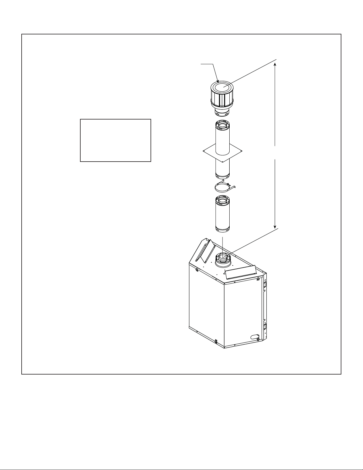
7 Appliance Preparation
A. Top Vent . . . . . . . . . . . . . . . . . . . . . . . . . . . . . . . . . . . . . . 19
B. Securing and Leveling the Appliance . . . . . . . . . . . . . . . . 20
8 Installing Vent Pipe
A. Assemble Vent Sections. . . . . . . . . . . . . . . . . . . . . . . . . . 21
B. Assemble Slip Sections . . . . . . . . . . . . . . . . . . . . . . . . . . 22
C. Secure the Vent Sections . . . . . . . . . . . . . . . . . . . . . . . . . 22
D. Disassemble Vent Sections . . . . . . . . . . . . . . . . . . . . . . . 23
E. Install Decorative Ceiling Components . . . . . . . . . . . . . . 23
F. Install Metal Roof Flashing . . . . . . . . . . . . . . . . . . . . . . . . 24
G Assemble and Install Storm Collar . . . . . . . . . . . . . . . . . . 24
H. Install Vertical Termination Cap . . . . . . . . . . . . . . . . . . . . 25
I. Install Decorative Wall Components . . . . . . . . . . . . . . . . 25
J. Heat Shield Requirements for Horizontal Termination . . . 25
K. Install Horizontal Termination Cap . . . . . . . . . . . . . . . . . . 26
9 Gas Information
A. Fuel Conversions . . . . . . . . . . . . . . . . . . . . . . . . . . . . . . . 27
B. Gas Pressures . . . . . . . . . . . . . . . . . . . . . . . . . . . . . . . . . 27
C. Gas Connection . . . . . . . . . . . . . . . . . . . . . . . . . . . . . . . . 27
10 Electrical Information
A. Recommendation for Wire . . . . . . . . . . . . . . . . . . . . . . . . 29
B. Optional Accessories . . . . . . . . . . . . . . . . . . . . . . . . . . . . 29
C. Connecting to the Appliance. . . . . . . . . . . . . . . . . . . . . . . 29
D. Intellifi re Ignition System Wiring . . . . . . . . . . . . . . . . . . . . 29
E. Junction Box Installation. . . . . . . . . . . . . . . . . . . . . . . . . . 31
11 Finishing
A. Mantel Projections . . . . . . . . . . . . . . . . . . . . . . . . . . . . . . 32
B. Facing Material . . . . . . . . . . . . . . . . . . . . . . . . . . . . . . . . . 32
C. Flooring Considerations . . . . . . . . . . . . . . . . . . . . . . . . . . 32
12 Appliance Setup
A. Remove Shipping Materials . . . . . . . . . . . . . . . . . . . . . . . 33
B. Clean the Appliance . . . . . . . . . . . . . . . . . . . . . . . . . . . . . 33
C. Accessories . . . . . . . . . . . . . . . . . . . . . . . . . . . . . . . . . . . 33
D. Pilot Air Defl ector and Grate . . . . . . . . . . . . . . . . . . . . . . . 33
E. Lava Rock, Vermiculite, Rockwool/Ember Placement . . . 33
F. Positioning the Logs . . . . . . . . . . . . . . . . . . . . . . . . . . . . . 34
G. Glass Assembly . . . . . . . . . . . . . . . . . . . . . . . . . . . . . . . . 37
H. Grilles and Trim . . . . . . . . . . . . . . . . . . . . . . . . . . . . . . . . 37
I. Shutter Setting . . . . . . . . . . . . . . . . . . . . . . . . . . . . . . . . . 37
13 Operating Instructions
A. Before Lighting Appliance. . . . . . . . . . . . . . . . . . . . . . . . . 38
B. Lighting Instructions (IPI) . . . . . . . . . . . . . . . . . . . . . . . . . 39
C. After Appliance is Lit . . . . . . . . . . . . . . . . . . . . . . . . . . . . . 40
D. Frequently Asked Questions . . . . . . . . . . . . . . . . . . . . . . 40
14 Troubleshooting
A. Intellifi re Ignition System . . . . . . . . . . . . . . . . . . . . . . . . . 41
15 Maintaining and Servicing Appliance
A. Maintenance Tasks . . . . . . . . . . . . . . . . . . . . . . . . . . . . . . 44
16 Reference Materials
A. Appliance Dimension Diagram . . . . . . . . . . . . . . . . . . . . . 45
B. Vent Components Diagrams . . . . . . . . . . . . . . . . . . . . . . 46
C. Service Parts . . . . . . . . . . . . . . . . . . . . . . . . . . . . . . . . . . 48
D. Limited Lifetime Warranty . . . . . . . . . . . . . . . . . . . . . . . . . 51
E. Contact Information . . . . . . . . . . . . . . . . . . . . . . . . . . . . . 53
Î
Î = Contains updated information.
Heat & Glo • Infi nity • 2003-900 Rev. M • 7/09 3
1
1
Listing and Code Approvals
A. Appliance Certifi cation
MODELS: Infi nity
LABORATORY: Underwriters Laboratories, Inc. (UL)
TYPE: Direct Vent Gas Appliance Heater
STANDARD: ANSI Z21.50-2000 • CSA2.22-M98 • UL307B
This product is listed to ANSI standards for “Vented Gas
Appliance Heaters” and applicable sections of “Gas Burning Heating Appliances for Manufactured Homes and
Recreational Vehicles”, and “Gas Fired Appliances for
Use at High Altitudes”.
NOT INTENDED FOR USE AS A PRIMAR Y HEAT SOURCE.
This appliance is tested and approved as either supplemental room heat or as a decorative appliance. It should not be
factored as primary heat in residential heating calculations.
B. Glass Specifi cations
Hearth & Home Technologies appliances manufactured
with tempered glass may be installed in hazardous locations such as bathtub enclosures as defi ned by the Con-
sumer Product Safety Commission (CPSC). The tempered
glass has been tested and certifi ed to the requirements
of ANSI Z97.1 and CPSC 16 CFR 1202 (Safety Glazing
Certifi cation Council SGCC# 1595 and 1597. Architectur-
al Testing, Inc. Reports 02-31919.01 and 02-31917.01).
This statement is in compliance with CPSC 16 CFR Sec-
tion 1201.5 “Certifi cation and labeling requirements”
which refers to 15 U.S. Code (USC) 2063 stating “…Such
certifi cate shall accompany the product or shall otherwise
be furnished to any distributor or retailer to whom the
product is delivered.”
Some local building codes require the use of tempered
glass with permanent marking in such locations. Glass
meeting this requirement is available from the factory.
Please contact your dealer or distributor to order.
D. High Altitude Installations
U.L. Listed gas appliances are tested and approved without requiring changes for elevations from 0 to 2000 feet in
the U.S.A. and Canada.
When installing this appliance at an elevation above 2000
feet, it may be necessary to decrease the input rating
by changing the existing burner orifi ce to a smaller size.
Input rate should be reduced by 4% for each 1000 feet
above a 2000 foot elevation in the U.S.A., or 10% for elevations between 2000 and 4500 feet in Canada. If the
heating value of the gas has been reduced, these rules
do not apply . To identify the proper orifi ce size, check with
the local gas utility.
If installing this appliance at an elevation above 4500 feet
(in Canada), check with local authorities.
WARNING
Do NOT use this appliance if any part has been under water.
Immediately call a qualifi ed service technician to inspect the
appliance and to replace any part of the control system and
any gas control which has been under water.
E. Non-Combustible Materials Specifi cation
Material which will not ignite and burn. Such materials are
those consisting entirely of steel, iron, brick, tile, concrete,
slate, glass or plasters, or any combination thereof.
Materials that are reported as passing ASTM E 136,
Standard Test Method for Behavior of Materials in a
Vertical Tube Furnace at 750ºC, shall be considered
non-combustible materials.
F. Combustible Materials Specifi cation
Materials made of or surfaced with wood, compressed
paper, plant fi bers, plastics, or other material that can ig-
nite and burn, whether fl ame proofed or not, or whether
plastered or unplastered shall be considered combustible
materials.
Note: This installation must conform with local codes. In the
absence of local c odes you must comply w ith the National
Fuel Gas Code, ANSI Z223.1 -latest edition in the U.S.A. and
the CAN/CGA B149 Installation Codes in Canada.
C. BTU Specifi cations
Models
(U.S. or Canada)
INFINITY (NG)
US
(0-2000 FT)
CANADA
(2000-4500 FT)
Maximum
Input BTU/h
35,000 34
31,500 35
Heat & Glo • Infi nity • 2003-900 Rev. M • 7/094
Orifi ce
Size (DMS)
G. Electrical Codes
NOTICE: This appliance must be electrically wired and
grounded in accordance with local codes or, in the absence
of local codes, with National Electric Code ANSI/NFPA
70-latest edition or the Canadian Electric Code CSA
C22.1.
• A 110-120 VAC circuit for this product must be protected
with ground-fault circuit-interrupter protection, in compliance
with the applicable electrical codes, when it is installed in
locations such as in bathrooms or near sinks.

Note: The following requirements reference various
Massachuset ts and national codes not contained in this
document.
H. Requirements for the Commonwealth of
Massachusetts
For all side wall horizontally vented gas fueled equipment
installed in every dwelling, building or structure used in
whole or in part for residential purposes, including those
owned or operated by the Commonwealth and where the
side wall exhaust vent termination is less than seven (7)
feet above fi nished grade in the area of the venting, in-
cluding but not limited to decks and porches, the following
requirements shall be satisfi ed:
Installation of Carbon Monoxide Detectors
At the time of installation of the side wall horizontal vented
gas fueled equipment, the installing plumber or gas fi tter
shall observe that a hard wired carbon monoxide detector
with an alarm and battery back-up is installed on the fl oor
level where the gas equipment is to be installed. In addition, the installing plumber or gas fi tter shall observe that
a battery operated or hard wired carbon monoxide detector with an alarm is installed on each additional level of
the dwelling, building or structure served by the side wall
horizontal vented gas fueled equipment. It shall be the
responsibility of the property owner to secure the services
of qualifi ed licensed professionals for the installation of
hard wired carbon monoxide detectors.
In the event that the side wall horizontally vented gas fueled equipment is installed in a crawl space or an attic,
the hard wired carbon monoxide detector with alarm and
battery back-up may be installed on the next adjacent
fl oor level.
In the event that the requirements of this subdivision can
not be met at the time of completion of installation, the
owner shall have a period of thirty (30) days to comply
with the above requirements; provided, however, that during said thirty (30) day period, a battery operated carbon
monoxide detector with an alarm shall be installed.
Inspection
The state or local gas inspector of the side wall horizontally vented gas fueled equipment shall not approve the
installation unless, upon inspection, the inspector observes carbon monoxide detectors and signage installed
in accordance with the provisions of 248 CMR 5.08(2)(a)1
through 4.
Exemptions
The following equipment is exempt from 248 CMR
5.08(2)(a)1 through 4:
• The equipment listed in Chapter 10 entitled “Equip-
ment Not Required To Be Vented” in the most current
edition of NFPA 54 as adopted by the Board; and
• Product Approved side wall horizontally vented gas fu-
eled equipment installed in a room or structure separate from the dwelling, building or structure used in
whole or in part for residential purposes.
MANUFACTURER REQUIREMENTS
Gas Equipment Venting System Provided
When the manufacturer of Product Approved side wall
horizontally vented gas equipment provides a venting
system design or venting system components with the
equipment, the instructions provided by the manufacturer
for installation of the equipment and the venting system
shall include:
• Detailed instructions for the installation of the venting
system design or the venting system components; and
• A complete parts list for the venting system design or
venting system.
Gas Equipment Venting System NOT Provided
When the manufacturer of a Product Approved side wall
horizontally vented gas fueled equipment does not provide the parts for venting the fl ue gases, but identifi es
“special venting systems”, the following requirements
shall be satisfi ed by the manufacturer:
Approved Carbon Monoxide Detectors
Each carbon monoxide detector as required in accordance with the above provisions shall comply with NFPA
720 and be ANSI/UL 2034 listed and IAS certifi ed.
Signage
A metal or plastic identifi cation plate shall be permanent-
ly mounted to the exterior of the building at a minimum
height of eight (8) feet above grade directly in line with the
exhaust vent terminal for the horizontally vented gas fueled heating appliance or equipment. The sign shall read,
in print size no less than one-half (1/2) inch in size, “GAS
VENT DIRECTLY BELOW. KEEP CLEAR OF ALL OBSTRUCTIONS”.
Heat & Glo • Infi nity • 2003-900 Rev. M • 7/09 5
• The referenced “special venting system” instructions
shall be included with the appliance or equipment installation instructions; and
• The “special venting systems” shall be Product Ap-
proved by the Board, and the instructions for that system shall include a parts list and detailed installation
instructions.
A copy of all installation instructions for all Product Approved side wall horizontally vented gas fueled equipment, all venting instructions, all parts lists for venting
instructions, and/or all venting design instructions shall
remain with the appliance or equipment at the completion
of the installation.
See Gas Connection section for additional Commonwealth of Massachusetts requirements.
2
2
Getting Started
A. Design and Installation Considerations
Heat & Glo direct vent gas appliances are designed to
operate with all combustion air siphoned from outside of
the building and all exhaust gases expelled to the outside.
No additional outside air source is required.
CAUTION
Check building codes prior to installation.
• Installation MUST comply with local, regional, state and
national codes and regulations.
• Consult local building, fi re offi cials or authorities having jurisdic-
tion about restrictions, installation inspection, and permits.
When planning an appliance installation, it’s necessary to
determine the following information before installing:
• Where the appliance is to be installed.
• The vent system confi guration to be used.
• Gas supply piping.
• Electrical wiring.
• Framing and fi nishing details.
• Whether optional accessories—devices such as a fan,
wall switch, or remote control—are desired.
C. Inspect Appliance and Components
WARNING
Inspect appliance and components for damage.
Damaged parts may impair safe operation.
• Do NOT install damaged components.
• Do NOT install incomplete components.
• Do NOT install substitute components.
Report damaged parts to dealer.
• Carefully remove the appliance and components from
the packaging.
• The vent system components and trim doors are shipped
in separate packages.
• The gas logs may be packaged separately and must be
fi eld installed.
• Report to your dealer any parts damaged in shipment,
particularly the condition of the glass.
• Read all of the instructions before starting the installation. Follow these instructions carefully during the
installation to ensure maximum safety and benefi t.
WARNING
WARNING
Keep appliance dry.
• Mold or rust may cause odors.
• Water may damage controls.
B. Tools and Supplies Needed
Before beginning the installation be sure that the following
tools and building supplies are available.
Reciprocating saw Framing material
Pliers High temperature caulking material
Hammer Gloves
Phillips screwdriver Framing square
Flat blade screwdriver Electric drill and bits (1/4 in.)
Plumb line Safety glasses
Level 1/2 - 3/4 inch length, #6 or #8 Self-drilling screws
Manometer Voltmeter
Tape measure Noncorrosive leak check solution
One 1/4 inch female connection (for optional fan).
• Installation and use of any damaged appliance or vent
system component.
• Modifi cation of the appliance or vent system.
• Installation other than as instructed by Hearth & Home
Technologies.
• Improper positioning of the gas logs or the glass door.
• Installation and/or use of any component part not approved
by Hearth & Home Technologies.
Any such action may cause a fi re hazard.
Hearth & Home Technologies disclaims any
responsibility for, and the warranty will be voided
by, the following actions:
Heat & Glo • Infi nity • 2003-900 Rev. M • 7/096
3
3
Framing and Clearances
Note:
• Illustrations reflect typical installations and are FOR
DESIGN PURPOSES ONLY.
• Illustrations/diagrams are not drawn to scale.
• Actual installation may vary due to individual design
preference.
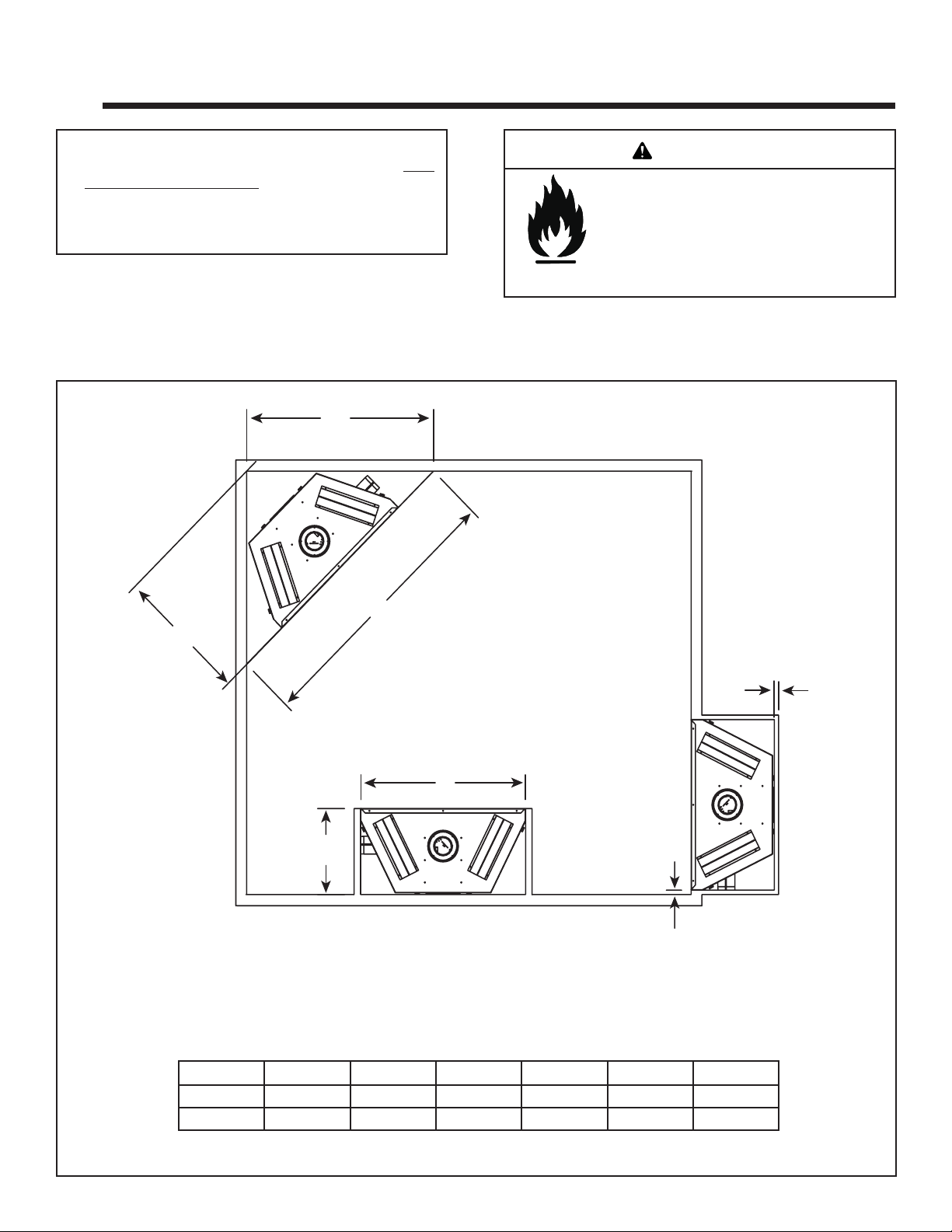
A. Selecting Appliance Location
When selecting a location for your appliance it is important to
consider the required clearances to walls (see fi gure 3.1).
C
WARNING
Fire Risk
Provide adequate clearance:
• Around air openings
• To combustibles
• For service access
Locate appliance away from traffi c areas.
Note: For actual appliance dimensions refer to Section 16.
B
A
E
D
In addition to these framing dimensions, also reference the following sections:
• Clearances and Mantel Projections (Sections 3.C and 3.D)
• Vent Clearances and Framing (Section 6).
1 INCH
F
Inches 61-1/4 30-5/8 43-5/16 20 39-1/4 1/2
Millimeters 1556 778 1100 508 997 13
Figure 3.1 Appliance Locations
ABCDEF
Heat & Glo • Infi nity • 2003-900 Rev. M • 7/09 7
B. Constructing the Appliance Chase
A chase is a vertical boxlike structure built to enclose the
gas appliance and/or its vent system. Vertical vents that
run on the outside of a building may be, but are not required to be, installed inside a chase.
Construction of the chase may vary with the type of building. These instructions are not substitutes for the requirements of local building codes. Local building codes MUST
be checked.
Chases should be constructed in the manner of all outside walls of the home to prevent cold air drafting problems. The chase should not break the outside building
envelope in any manner.
Walls, ceiling, base plate and cantilever fl oor of the chase
should be insulated. Vapor and air infi ltration barriers
should be installed in the chase as per regional codes for
the rest of the home. Additionally, in regions where cold
air infi ltration may be an issue, the inside surfaces may be
sheetrocked and taped for maximum air tightness.
To further prevent drafts, the wall shield and ceiling
fi restops should be caulked with high temperature caulk
to seal gaps. Gas line holes and other openings should
be caulked with high temperature caulk or stuffed with
unfaced insulation. If the appliance is being installed on a
cement surface, a layer of plywood may be placed underneath to prevent conducting cold up into the room.
C. Clearances
WARNING
Fire Risk.
Odor Risk.
• Install appliance on hard metal or wood surfaces
extending full width and depth of appliance.
• Do NOT install appliance directly on carpeting,
vinyl, tile or any combustible material other than
wood.
WARNING
Fire Risk.
• Construct chase to all clearance specifi cations
in manual.
• Locate and install appliance to all clearance
specifi cations in manual.
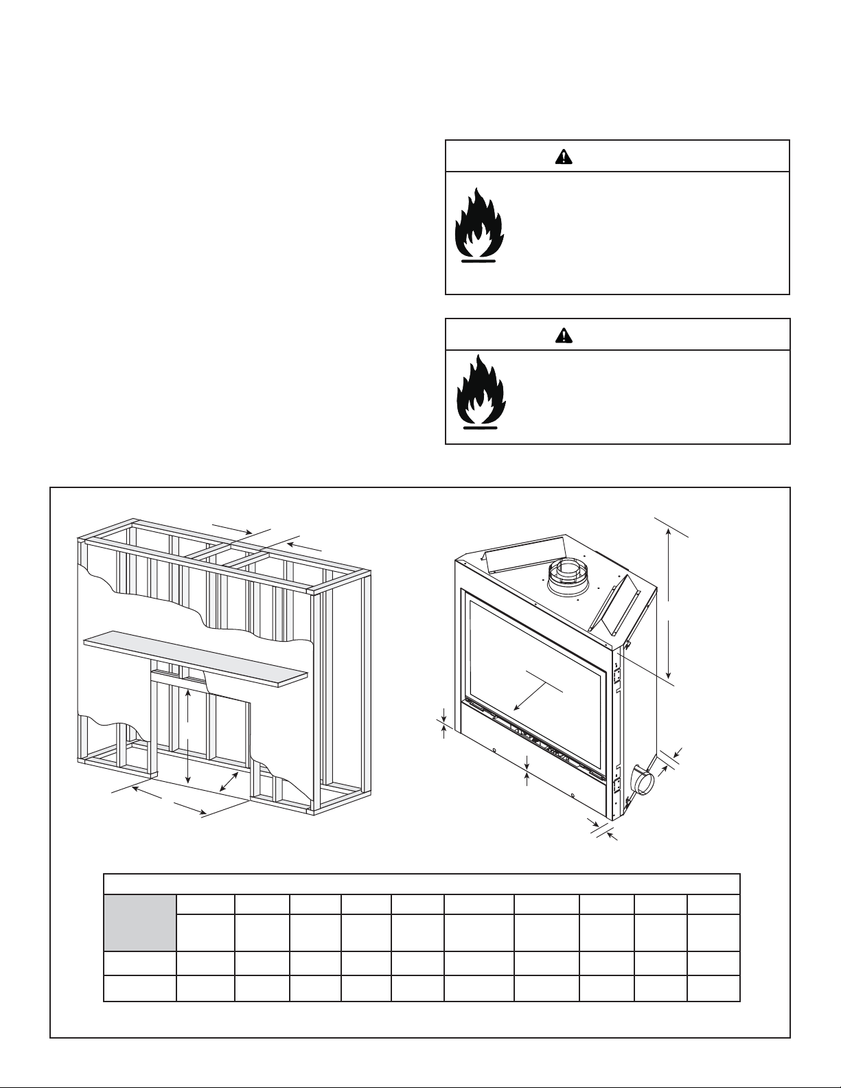
A
FROM TOP
OF UNIT
E
F
B
C
D
J
H
G
I
Clearance to Combustibles
ABCDE F G HIJ
Rough
Opening
(Vent Pipe)
Inches 10 40 20 39-1/4 31 0 0 1/2 1/2 36
Rough
Opening
(Height)
Rough
Opening
(Depth)
Rough
Opening
(Width)
Clearance
to Ceiling
Combustible
Floor
Combustible
Flooring
Behind
Appliance
Sides of
Appliance
Front of
Appliance
Millimeters 254 1016 508 997 787 0 0 13 13 914
Figure 3.2 Clearances to Combustibles
Heat & Glo • Infi nity • 2003-900 Rev. M • 7/098
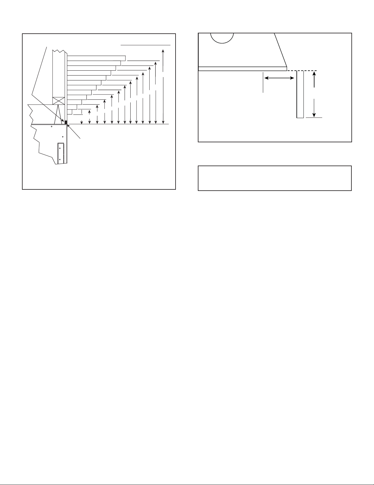
D. Mantel Projections
1/2 NON-COMBUSTIBLE
MATERIAL
2
1
10
9
8
7
6
5
4
3
2
1
TOP FRONT EDGE
OF FIREPLACE
NOTE: ALL DIMENSIONS
SHOWN IN INCHES.
5
4
3
12
11
8
7
6
CEILING
31
12
11
10
9
Figure 3.3 Clearances to mantels or other combustibles
above appliance
E. Flooring Considerations
If the fi replace is to be installed prior to fi nished fl oor con-
struction (i.e. tile, carpet, etc.) in front of the fi replace, pro-
visions must be made to accommodate for the difference
in height between the fl oor underneath the fi replace and
the fi nished fl oor to be installed in front of the fi replace.
TOP VIEW
2-1/2 in.
UNLIMITED
Note: Clearance from opening to
perpendicular wall that extends
past the front edge of fi replace.
Figure 3.4 Clearances to Mantel Legs or Wall Projections
(Acceptable on both sides of opening.)
F. Hearth Extension
A hearth extension may be desirable for aesthetic reasons.
However, ANSI or CAN/CGA testing standards do not require
hearth extensions for gas fi replace appliances.
Heat & Glo • Infi nity • 2003-900 Rev. M • 7/09 9
4
4
Termination Locations
A. Vent Termination Minimum Clearances
WARNING
Fire Risk.
Explosion Risk.
Maintain vent clearance to combustibles as
specifi ed.
• Do not pack air space with insulation or other
materials.
Failure to keep insulation or other materials
away from vent pipe may cause fi re.
Measure vertical clearances from this surface.
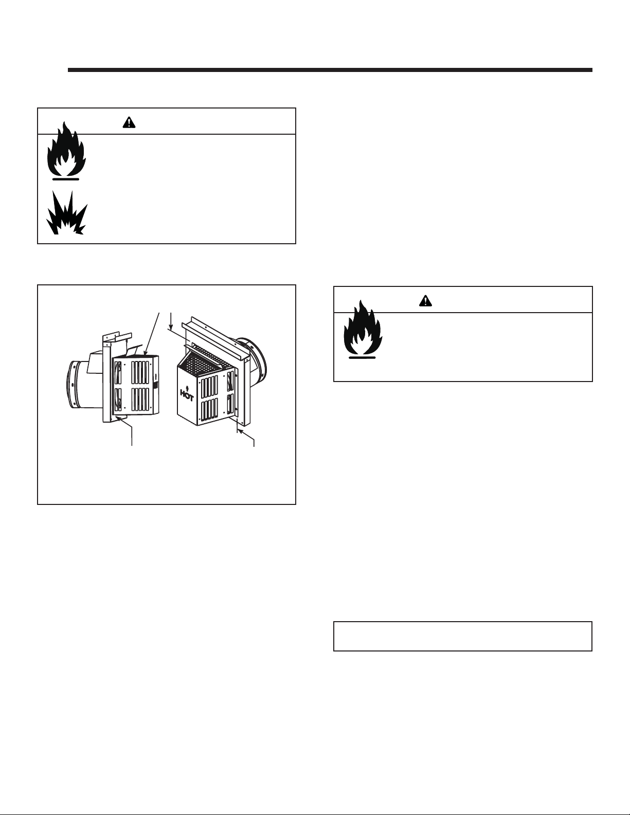
B. Vent Termination
For Horizontal Terminations - The trapezoidal cap SLPTRAP1 and SLP-TRAP2 are the only caps that are approved to terminate a horizontal vent run.
For Horizontal Terminations - To attach and secure the
termination to the last section of horizontal vent:
• Rotate and interlock the ends as described at the
beginning of the Installing Vent Components section.
• The termination kit should pass through the wall fi restop
from the exterior of the building.
• Adjust the termination cap to its fi nal exterior position on
the building.
WARNING
Fire Risk.
The termination cap must be oriented so that
the arrow is pointing up.
If termination cap is installed incorrectly, the
clearances to combustibles will not be met.
Measure horizontal clearances from this surface.
(See Figure 4.4 for specifi c clearances)
Figure 4.1
Fasten heat shield and fi restop simultaneously.
For trapezoidal cap termination kits:
• Using screws secure the cap to the exterior wall through
the fl anges in the cap.
• Seal the joint between the pipe and the exterior
fi restop.
The bottom of the vent termination cap must be a minimum of 12 inches (305 mm) above ground level (grade).
The top of the cap must be a minimum of 18 inches (457
mm) below combustible material, such as a deck. The
side of the cap must be a minimum of 6 inches (152 mm)
away from a parallel outside wall. Venting terminals shall
not be recessed into a wall or siding. See fi gure 4.5 for
vent termination clearances.
Note: For vinyl siding use protector k it VPK-Infi nity or
DVP-BEK2.
Heat & Glo • Infi nity • 2003-900 Rev. M • 7/0910
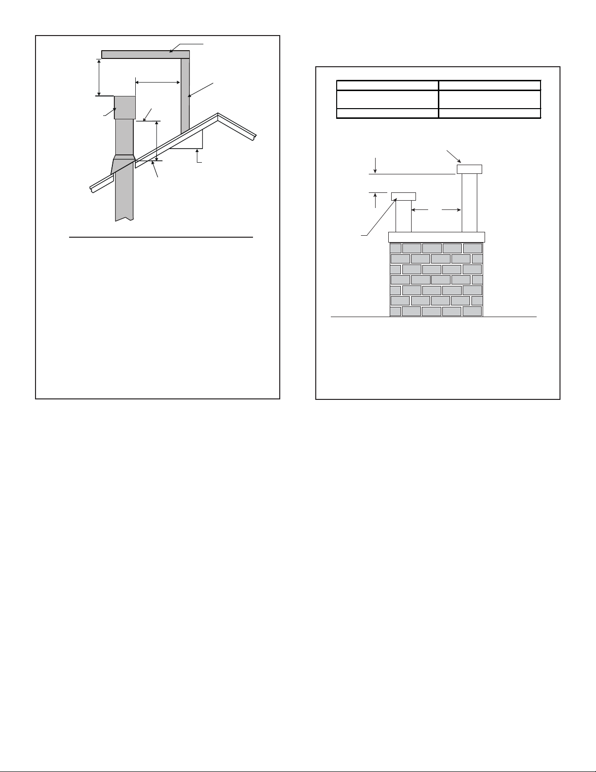
HORIZONTAL
OVERHANG
Figure 4.2 specifi es minimum vent heights for various
pitched roofs.
2 FT.
MIN.
GAS DIRECT VENT
TERMINATION CAP
2 FEET MIN.
LOWEST
DISCHARGE
OPENING
H (MIN.) - MINIMUM HEIGHT FROM ROOF
TO LOWEST DISCHARGE OPENING
X
12
ROOF PITCH
VERTICAL
WALL
IS X/ 12
Roof Pitch H (Min.) Ft.
Flat to 6/12...........................................................1.0*
Over 6/12 to 7/12 .................................................1.25*
Over 7/12 to 8/12 .................................................1.5*
Over 8/12 to 9/12 .................................................2.0*
Over 9/12 to 10/12 ...............................................2.5
Over 10/12 to 11/12 .............................................3.25
Over 11/12 to 12/12 .............................................4.0
Over 12/12 to 14/12 .............................................5.0
Over 14/12 to 16/12 .............................................6.0
Over 16/12 to 18/12 .............................................7.0
Over 18/12 to 20/12 .............................................7.5
Over 20/12 to 21/12 .............................................8.0
* 3 foot minimum in snow regions
Figure 4.2 Minimum height from roof to lowest discharge
opening
6in.(minimum)upto20in.
152 mm/508 mm
20 in. and over 0 in. minimum
18 in. minimum
457 mm
Gas, Wood or Fuel Oil
Termination Cap
B
A*
Gas
Termination
Cap **
AB
If using decorative cap cover(s), this distance may need to be
*
increased. Refer to the installation instructions supplied with the
decorativecap cover.
In a staggered installation with both gas and wood terminations, the
**
wood termination cap must be higher than the gas termination cap.
Figure 4.3 Multiple Vertical Termination
Heat & Glo • Infi nity • 2003-900 Rev. M • 7/09 11
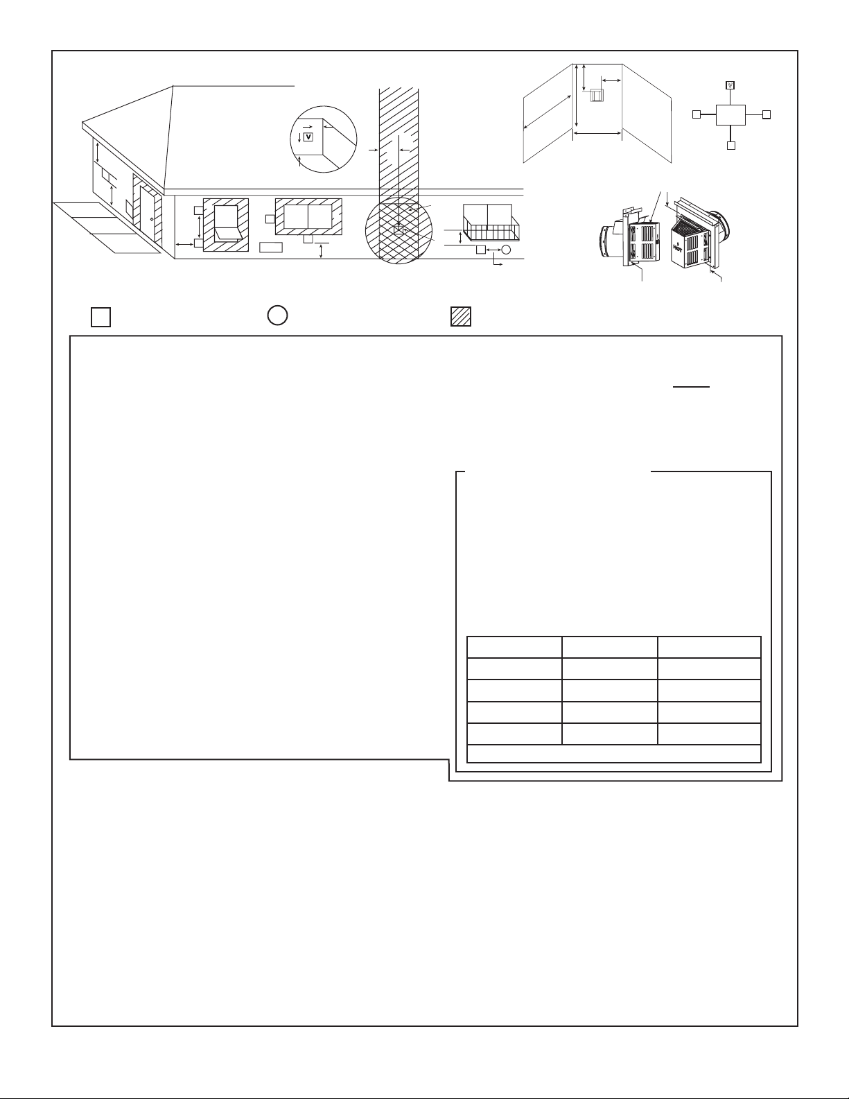
O
N
P
E
C
V
B
J
V
B
V
i
D
V
A
V
B
V
A
F
U.S
(3 FT.)
M
G
X
V
H or i
R
Q
(See Note 2)
Measure vertical clearances from this surface.
V
L
K
K
Electrical
V
Service
V
C
V
Measure horizontal clearances from this surface.
= VENT TERMINAL
V
X
= AIR SUPPLY INLET
A = 12 inches.................clearances above grade, veranda,
(See Note 1)
porch, deck or balcony
B = 12 inches.................clearances to window or door
that may be opened, or to permanently closed window. (Glass)
C = 18 inches.................vertical clearance to unventilated
soffi t or to ventilated soffi t located
above the terminal
30 inches .................for vinyl clad soffi ts and below
electrical service
D = 9 inches...................clearance to outside corner
E = 6 inches...................clearance to inside corner
F = 3 ft. (Canada) ..........not to be installed above a gas
meter/regulator assembly within 3
feet (90 cm) horizontally from the
center-line of the regulator
G = 3 ft ...........................clearance to gas service regulator
vent outlet
H = 9 inches (U.S.A.)
12 inches (Canada) clearance to non-mechanical
(See Note 2)
air supply inlet to building or the
combustion air inlet to any other
appliance
i = 3 ft. (U.S.A.)
6 ft. (Canada) ...........clearance to a mechanical (pow-
(See Note 2)
** a vent shall not terminate directly above a sidewalk or paved driveway
which is located between two single family dwellings and serves both
dwellings.
*** only permitted if veranda, porch, deck or balcony is fully open on a
minimum of 2 sides beneath the fl oor, or meets Note 2.
Note 1: On private property where termination is less than 7 feet above a
sidewalk, driveway, deck, porch, veranda or balcony, use of a listed cap
shield is suggested. (See vents components page)
Note 2: T ermination in a covered alcove space (spaces open only on one
side and with an overhang) are permitted with the dimensions specifi ed
for vinyl or non-vinyl siding and soffi ts. 1. There must be 3 feet minimum
between termination caps. 2. All mechanical air intakes within 10 feet
of a termination cap must be a minimum of 3 feet below the termination
cap. 3. All gravity air intakes within 3 feet of a termination cap must be
a minimum of 1 foot below the termination cap.
Figure 4.4 Minimum Clearances for Termination
ered) air supply inlet
= AREA WHERE TERMINAL IS NOT PERMITTED
J** = 7 ft. ......................... clearance above paved
(See Note 1)
sidewalk or a paved driveway
located on public property
K = 6 inches................. clearance from sides of electri-
(See Note 5)
cal service
L = 12 inches................ clearance above electrical
(See Note 5)
service
Covered Alcove Applications
M*** = 18 inches .............clearance under veranda, porch,
42 inches ......... vinyl
N = 6 inches ........... non-vinyl sidewalls
12 inches ......... vinyl sidewalls
O = 18 inches ......... non-vinyl soffi t and overhang
42 inches ......... vinyl soffi t and overhang
P = 8 ft.
1 cap 3 feet 2 x Q
2 caps 6 feet 1 x Q
3 caps 9 feet 2/3 x Q
4 caps 12 feet 1/2 x Q
Q
= # termination caps x 3 R
MIN
Note 3: Local codes or regulations may require different
clearances.
Note 4: Termination caps may be hot. Consider their proximity to
doors or other traffi c areas.
Note 5: Location of the vent termination must not interfere with
access to the electrical service.
In the U.S and Canada: Vent system termination is NOT permitted
in screened porches.
Vent system termination is permitted in porch areas with two or more
sides open. You must follow all side walls, overhang and ground
clearances as stated in the instructions.
Heat & Glo assumes no responsibility for the improper performance
of the appliance when the venting system does not meet these
requirements.
deck, balcony or overhang
Q
MIN
= (2 / # termination caps) x Q
MAX
R
MAX
ACTUAL
ACTUAL
ACTUAL
ACTUAL
ACTUAL
CAUTION: IF EXTERIOR WALLS ARE FINISHED WITH VINYL SIDING, IT IS SUGGESTED THAT A VINYL PROTECTOR KIT BE INSTALLED.
Heat & Glo • Infi nity • 2003-900 Rev. M • 7/0912
5
5
Vent Information and Diagrams
A. Vent Table Key
The abbreviations listed in this vent table key are used in
the vent diagrams.
Symbol Description
First section (closest to appliance) of vertical length
V
1
Second section of vertical length
V
2
First section (closest to appliance) of horizontal length
H
1
Second section of horizontal length
H
2
Vertical
12 in.
8-1/2 in.
8-1/2 in.
WARNING
Fire Hazard.
Explosion Risk.
Asphyxiation Risk.
Do NOT connect this gas appliance to a chimney
fl ue serving a separate solid-fuel or gas burning
appliance.
• Vent this appliance directly outside.
• Use separate vent system for this appliance.
May impair safe operation of this appliance or
other appliances connected to the fl ue.
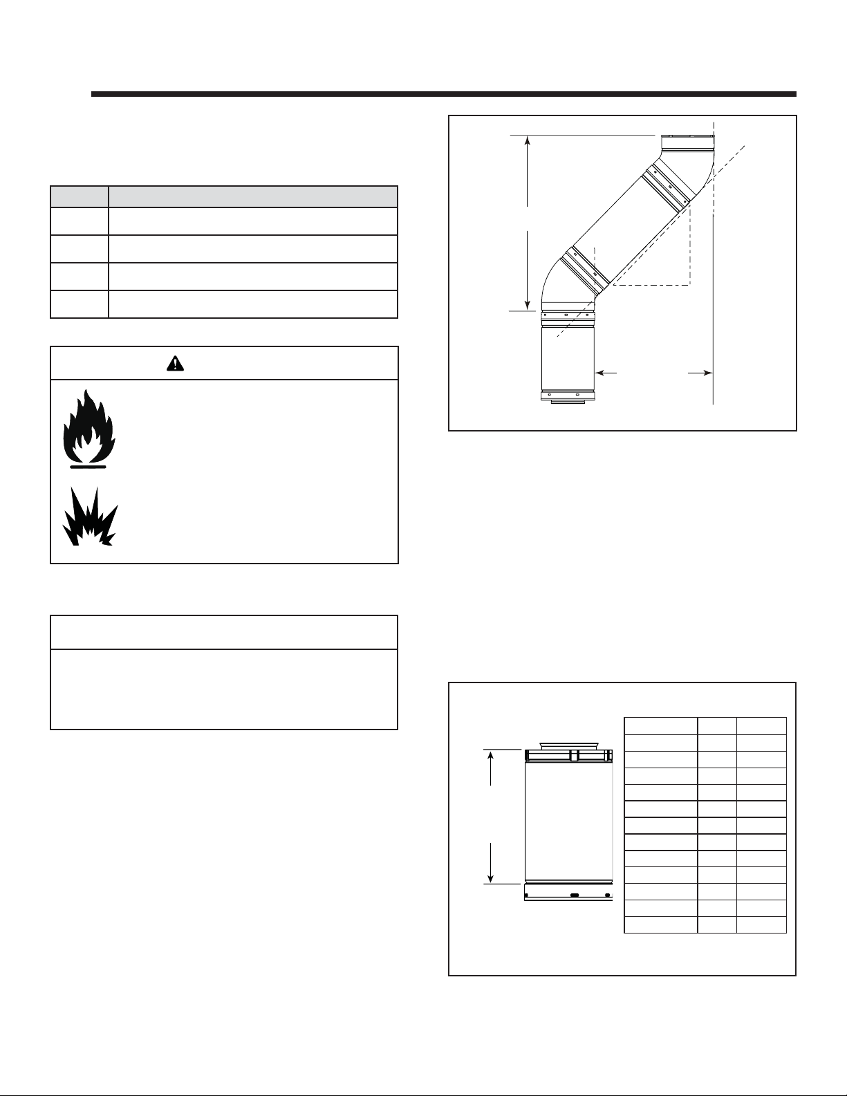
B. Use of Elbows
CAUTION
ALL vent confi guration specifi cations MUST be followed.
• This product is tested and listed to these specifi cations.
• Appliance performance will suffer if specifi cations are not
followed.
Diagonal runs have both vertical and horizontal vent aspects when calculating the effects. Use the rise for the
vertical aspect and the run for the horizontal aspect (see
Figure 5.1).
Two 45º elbows may be used in place of one 90º elbow . On
45º runs, one foot of diagonal is equal to 8-1/2 (216 mm)
inches horizontal run and 8-1/2 (216 mm) inches vertical
run. A length of straight pipe is allowed between two 45º
elbows (see Figure 5.1).
Horizontal
Figure 5.1
C. Measuring Standards
Vertical and horizontal measurements listed in the vent
diagrams were made using the following standards.
• Pipe measurements are shown using the effective length
of pipe (see Figure 5.2).
• Horizontal terminations are measured to the outside
mounting surface (fl ange of termination cap) (see Figure
4.1).
• Vertical terminations are measured to bottom of termination cap.
• Horizontal pipe installed level with no rise.
Effective Height/Length
Effective
Height/
Length
Pipe
SLP4 4 102
SLP6 6 152
SLP12 12 305
SLP24 24 610
SLP36 36 914
SLP48 48 1219
SLP6A 2 - 6 51 - 152
SLP12A 2 - 12 51 - 305
SLP-FLEX-2 24 610
SLP-FLEX-3 36 914
SLP-FLEX-5 60 1524
SLP-FLEX-10 120 3048
inches mm
Figure 5.2 SLP Pipe Effective Length
Heat & Glo • Infi nity • 2003-900 Rev. M • 7/09 13
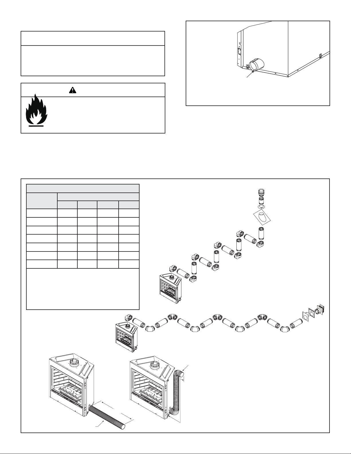
D. Outside Air
CAUTION
Install fresh air intake in the same pressure zone as the
exhaust pipe termination cap. Failure to do so may cause
over-heating after the unit is shut down, potentially resulting
in damaged components.
WARNING
Fire Hazard.
This unit is designed to operate using outside
combustion air. It is mandatory to install an AKCFX air kit. The 4 inch (102 mm) duct collar for
the air kit IS PROVIDED ON the fi replace.
The combustion air for this fi replace is supplied by AK-CFX
outside air kit. This kit may extend up to 40 feet from the fi re-
place to the outside air inlet cap (provided with AK-CFX).
It is required to seal all outside air duct connections with
an RTV silicone caulk.
MINIMUM FLEXIBLE INTAKE DUCTING DIAMETERS
Length of
the duct run
10 feet 4 in. 4 in. 4 in. 4 in.
15 feet 4 in. 4 in. 4 in. 4 in.
20 feet 4 in. 4 in. 4 in. 5 in.
25 feet 4 in. 4 in. 4 in. 5 in.
30 feet 4 in. 4 in. 5 in. 5 in.
35 feet 4 in. 5 in. 5 in. 6 in.
40 feet 4 in. 5 in. 6 in. 6 in.
Upsizing from the minimum diameter of the duct is acceptable.
Use an appropriate adapter collar.
Avoid sharp bends, kinks, and sags in the fl exible ducting.
If using fl exible ducting larger than 4 in., the duct can be
reduced back to 4 in. for connection to the intake cap.
Combustion air duct may be vented in any direction,
including downward.
One 90º Two 90º Three 90º Four 90º
Number of bends
COMBUSTION DUCT
COLLAR FOR
AK-CFX AIR KIT
Figure 6. Unit with duct collar
See Table 1 for duct diameter requirements.
It is RECOMMENDED that the outside air inlet cap be in-
stalled on the same exterior wall as the SLK-01TRD exhaust termination cap to ensure they are in the same pressure zone. Required distance between intake and exhaust
termination caps is 3 feet (USA) and 6 feet (Canada).
Outside air kit AK-CFX must terminate horizontally and
must be used with the provided inlet cap.
Any combination in-between
would be applicable.
Total H (Horizontal run) = 50 feet maximum.
Total V (Vertical run) = 40 feet maximum.
Note: The exhaust may never have a vertical drop.
Exhaust Duct
Figure 7.
COMBUSTION
AIR DUCT
40 FT.
MAXIMUM
Install combustion air duct with
inlet cap on same exterior wall of
COMBUSTION
AIR DUCT
the dwelling whenever possible.
Unit could have up to eight elbows
off the top, with a maximum of 50
feet horizontal before any vertical,
however, a vertical run of 40 feet
40 FT.
MAXIMUM
maximum could be introduced at
any point of the horizontal run and
even right off the top of the unit.
Heat & Glo • Infi nity • 2003-900 Rev. M • 7/0914
STRAIGHT UP
VERTICAL VENTING
V (FT.)
40’ MAX. (12.4 m)
CAP
V
Figure 8. Straight Up Vertical Venting
Heat & Glo • Infi nity • 2003-900 Rev. M • 7/09 15
6
6
Vent Clearances and Framing
A. Pipe Clearances to Combustibles
WARNING
Fire Risk.
Explosion Risk.
Maintain vent clearance to combustibles as
specifi ed.
• Do not pack air space with insulation or
other materials.
Failure to keep insulation or other materials
away from vent pipe may cause fi re.
Note: Heat shields MUST overlap by a minimum of 1-1/2 in. (38 mm).
• SLP heat shield - designed to be used on a wall 4-3/8 in. to 7-5/8
in. (111 mm to 194 mm thick).
• If wall thickness is less than 4-3/8 the existing heat shields must be
field trimmed. If wall thickness is greater than 7-5/8 in. a DVPHSM-B will be required.
2-1/2 in. (64 mm)
top clearance at
wall shield firestops
3 in. (76 mm)
top clearance
Heat
Shields
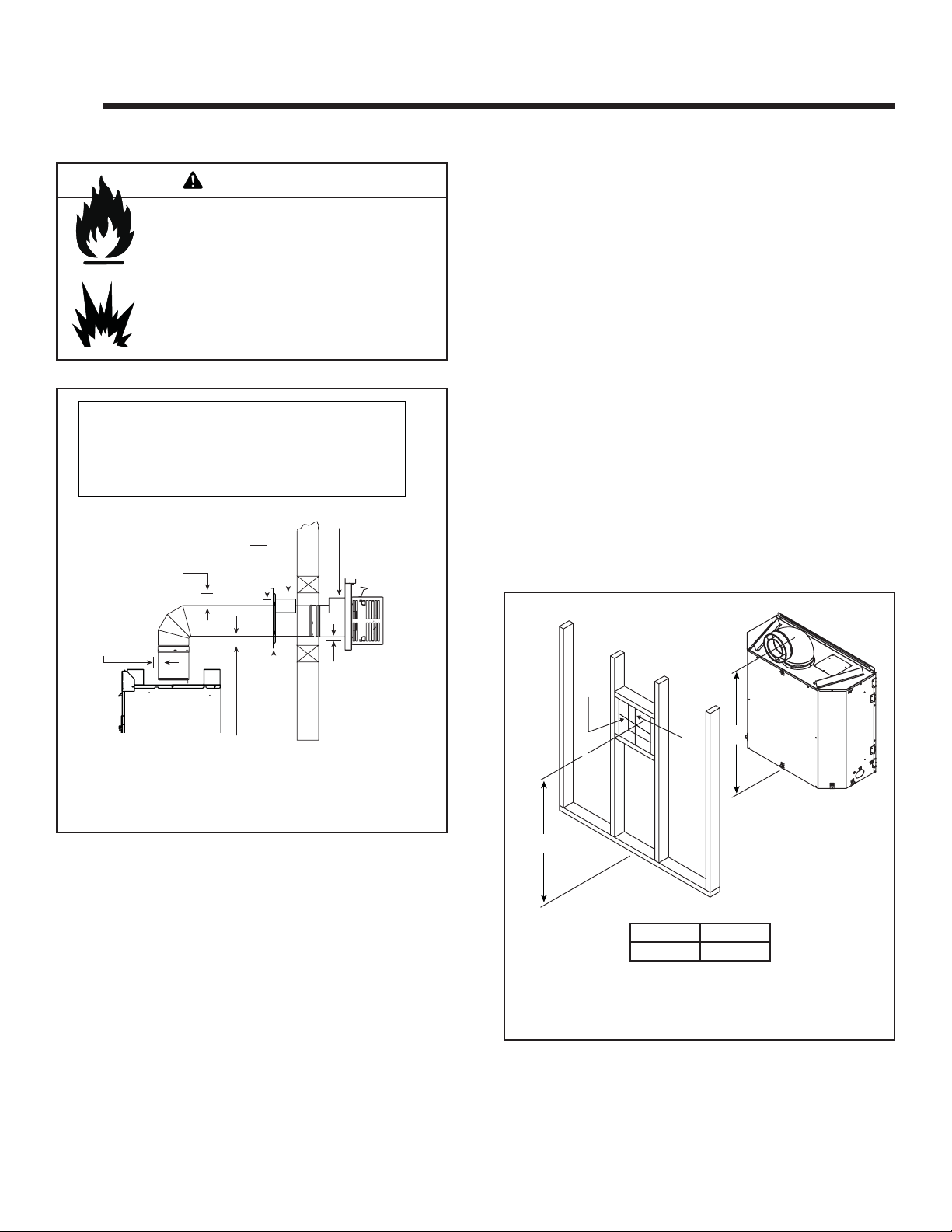
B. Wall Penetration Framing
Combustible Wall Penetration
Whenever a combustible wall is penetrated, you must
frame a hole for the wall shield fi restop. The wall shield
fi restop maintains minimum clearances and prevents cold
air infi ltration.
• The opening must be framed on all four sides using the
same size framing materials as those used in the wall
construction.
• SLP pipe - A wall shield fi restop must be placed on each
side of an interior wall. A minimum 1-1/2 in. (38 mm)
overlap of attached heat shields must be maintained.
• See Section 8.L. for information for regarding the installation of a horizontal termination cap.
Non-Combustible Wall Penetration
If the hole being penetrated is surrounded by noncombustible materials such as concrete, a hole with diameter
one in. greater than the pipe is acceptable.
Whenever a non-combustible wall is penetrated, the wall
shield fi restop is only required on one side and no heat
shield is necessary.
1 in. (25 mm)
clearance around
vertical sections
Wall
Shield
Firestop
1 in. (25 mm)
clearance
bottom and sides
Figure 6.1 Horizontal venting clearances to combustible
materials
1/2 in. (13 mm) bottom
clearance at wall
shield firestops
WALL
10 in.
A*
* Shows center of vent framing hole for top venting. The center of the hole
is one (1) inch (25.4 mm) above the center of the horizontal vent pipe.
Figure 6.2 Exterior Wall Hole
10 in.
B
A* B
44 -3/4 in. 43 -3/4 in.
Heat & Glo • Infi nity • 2003-900 Rev. M • 7/0916
 Loading...