

Page 1
HEAT-ZONE-WOOD AIR DUCT KIT
Ceiling Register
Wall Register
Floor Register
Two Duct Kits
Ceiling Register
12" (305mm) minimum clearance
from register to ceiling
Part No: HEAT-ZONE-WOOD
APPROVALS
The Heat-Zone-Wood air duct kit is approved to
use on EPA Fireplaces 7100FP, North Star and
Constitution.
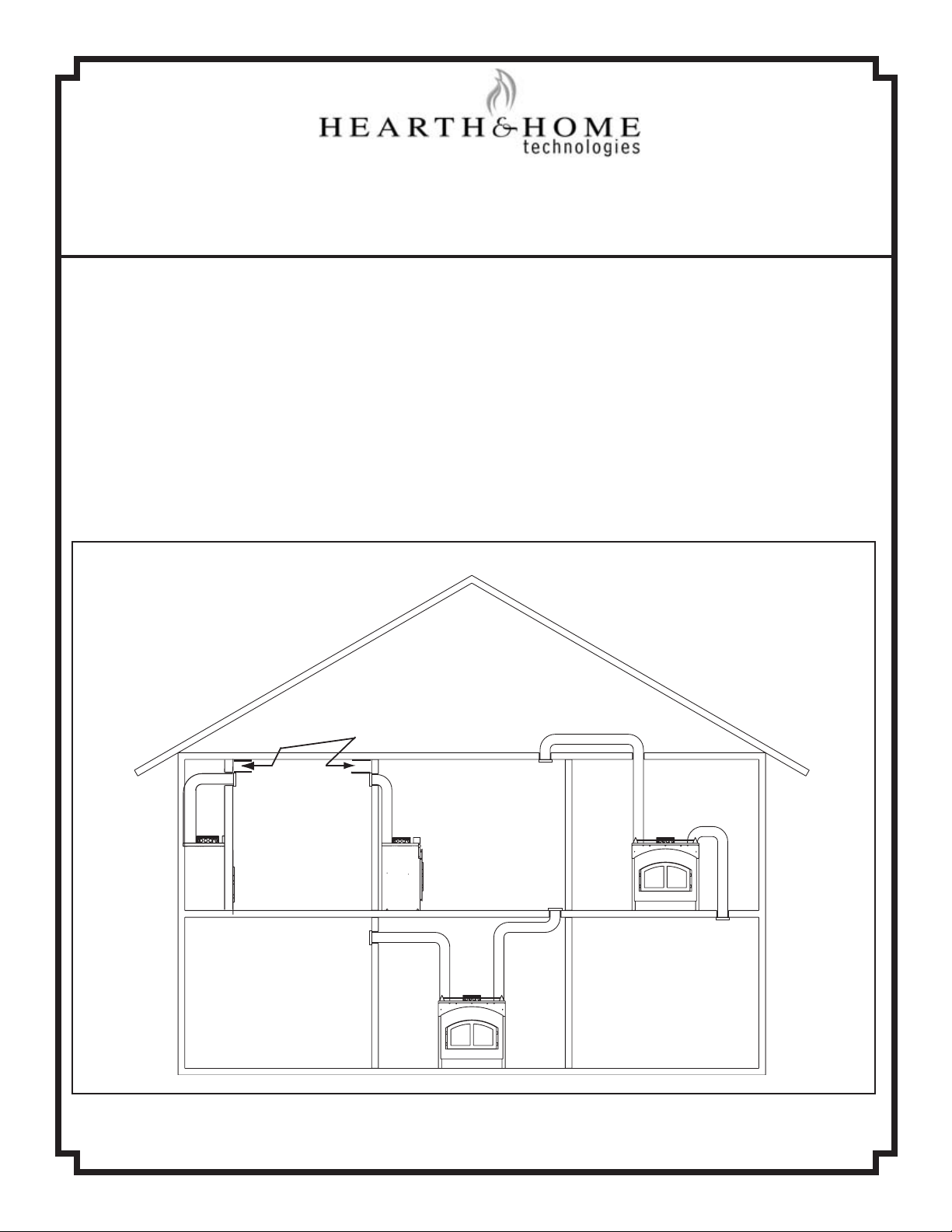
INTRODUCTION
The Heat-Zone-Wood accessory kit conveys warm
air from the replace through air duct(s) to remote
locations in the same room or other rooms of the
building. See Figure 1. One or two Heat-Zone
kits can be installed on the replace.
Possible Air Duct Runs / Locations
PRELIMINARY PREPARATION
1. Contents of kit:
• 16” Snap Lock Starter pipe - cut to
desired length (See Figure 2 on page 2).
• Mounting Plate
• Adapter
• Fan Housing Assembly
• Return Air Grille
• Gasketing
• Variable Speed Wall Rheostat
• Fastener Package
If any parts are missing or damaged, contract your dealer
before starting installation. DO NOT install a damaged kit.
1445 North Highway
Colville, WA 99114
7015-114 September 5, 2003 Page 1 of 4
Figure 1
www.quadrare.com
Page 2
2. This kit is tested and safe when installed in
Adapter
Mounting
Plate
Starter Pipe
Knockout
Cut a
3
"
(
7
6
m
m
)
ho
l
e
in
in
su
l
a
t
io
n
3-13/16"
(97mm)
3-1/8" (79mm)
C
L
accordance with this installation manual. It is your
responsibility to read all instructions before starting installation and to follow these instructions
carefully during installations.
3. Installation of this kit MUST by performed by a
qualied service technician.
4. The Heat-Zone-Wood kit is carefully engineered
and must be installed only as specied. If you
modify it or any of its components you will void
the warranty and you may possibly cause a re
hazard. Installation must be done according to
applicable local, state, provincial and/or national
codes.
5. CAUTION: ALL wiring should be done by a
qualied electrician and shall be in compliance
with local codes and with the National Electric
Code ANSI/NFPA No. 70-current (in the United
States) or with the current CSC22.1 Canadian
Electric Code (in Canada).
6. Plan the location of the replace and warm air
duct run(s).
DUCT RUN REQUIREMENTS
MAXIMUM Duct Run = 40-ft (12m)
MINIMUM Duct Run = 36” (914mm)
DUCTING MATERIAL
6 inch (152mm) B-Vent Only
DO NOT DUCT into existing furnace plenum
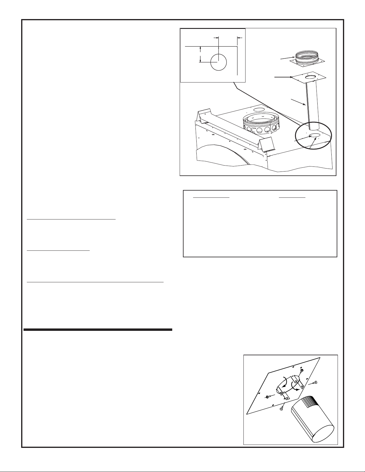
Figure 2
Run Length Cut Pipe
20 - 40 ft (6-12m) 2” (51mm)*
*A minimum of 2” (51mm) pipe must be used to
cover the raw insulation to prevent it tfrom blowing
out through the Return Air Grille.
10 - 20 ft (3 - 6m) 8” (203mm)
3 - 10 ft (1 - 3m) No cut needed**
**Use full 16” (406mm) as supplied
Figure 3
MINIMUM CLEARANCE TO COMBUSTIBLES
1 inch (25mm) from the B-Vent
1
/2 inch (13mm) from top & bottom of outlet box
0 inch (0mm) from the sides of outlet box
12” (305mm) from wall register to ceiling*
*(See Figure 1 on page 1).
INSTALLATION
1. Remove the knockout or cover plate from the top of
the replace and discard it. See Figure 2.
2. Cut a 3” (76mm) hole in the insulation board as per
the dimensions shown in Figure 2.
3. Determine the necessary length of starter pipe from
the following table and cut as required. See Figure 3.
4. The starter pipe is shipped at. After cutting to the
required length, manually roll the pipe together and
snap lock into place. NOTE: It is important the pipe
length be adhered to or it will affect the performance of your replace.
7015-114 September 5, 2003 Page 2 of 4
5. On the Mounting Plate, hand bend the tabs downward. Slide the tabs over the outside of the starter
pipe. Secure with 4 sheet metal screws included in
fasteners package. Figure 4
6. Slide the starter pipe into the replace, matching
the holes in the plate to the holes in the replace.
7. Place the Adapter on the Mounting Plate lining up
holes. Using the 4 sheet metal screws included in the
kit, secure the Adapter and Mounting Plate into re-
Figure 4
Page 3

place. After securing to the replace, tape down
Securely Twist
Lock B-Vent to
Adapter
Secure B-Vent to Fan Housing
with sheet metal screws
Return Air Grille
Install with Louvers
pointed down
Bracket
Can rotate
180
o
2 x 4 Wall
Fan Housing
1/2" (13mm)
clearance to
combustibles
must be
maintained.
2 x 4 wall
Sheet Rock
S
e
a
l
g
ri
lle
u
s
in
g
g
a
s
k
e
tin
g
s
u
p
p
li
e
d
w
ith
th
e
k
it
Leave 1/4" (6mm) clearance from
all 4 outer edges
the Adapter edges to the top of the replace with
aluminum tape to prevent leakage.
Also screw the B-Vent to the outlet box on the fan
housing. See Figure 6.
Support duct at intervals of no
greater than 4 ft (1 m) as required by local code.
8. Determine the location for the air register and
fan housing assembly. Cut a 7-5/8” x 13-5/8” (143
x 346mm) hole between framing members (wall
studs or oor joists). The brackets can be rotated
180° and mounted to the back side of the 2 x 4 if
necessary. See Figure 6.
NOTE: The fan and electrical connections
must be accessible for servicing per local code
requirements.
NOTE: If the fan housing is installed in a 2
x 4 wall, the front of the housing will protrude
approximately 1/4” (6mm) from the nished wall.
See Figure 5.
WARNING! 1/2” (13mm) clearance to
combustibles must be maintained.
8. Attach enough 6” (152mm) B-Vent as required
for your installation to the fan housing. A max-
imum of (4) 90° elbows is recommended.
Securely twist lock the B-Vent to the Adapter.
NOTE: Secure the duct so that clearance to the
replace outer wrap is maintained. Tape all seams
with aluminum tape 1-1/4” (32mm) minimum width
or as specied by local codes.)
9. Seal all the way around the inside of the Return
Air Grille to prevent hot air being drawn back into the
venting system using gasketing supplied with the kit.
Leave 1/4”(6mm) clearance from all 4 outer edges.
Trim excess gasketing. See Figure 7.
Figure 6
Figure 5
Figure 7
7015-114 September 5, 2003 Page 3 of 4
Page 4

Junction Box Removed
Wire Clamp
Wire Nuts
Junction Box
Black
White
10. Install the variable speed wall rheostat (with
Remove 2
screws from
Junction Box
access panel
Remove 2 bolts from fan
bracket
setting on “OFF”) in a convenient location. This
switch will control the Heat-Zone fan operation.
11. Remove the Junction Box. Wire 110 VAC
service TO the wall rheostat and FROM the wall
rheostat to the fan Junction Box. Use wire nuts
to secure the 110 VAC service wires to the hot
(black) and neutral (white) fan wires and screw
the 110 VAC ground wire to the Junction Box.
See Figure 8.
12. Secure the Return Air Grille to the fan housing
making sure it is ush. The grille must be installed
with the louvers pointing down.
NOTE: DO NOT USE ADJUSTABLE REGISTERS.
13. Complete the replace installations as per
the instructions found in your Owner’s Manual.
OPERATION
1. Start the replace per the instructions found in
your Owner’s Manual and allow it to warm up.
MAINTENANCE
1. Service and maintain the replace as per the
instructions in your Owner’s Manual.
2. Keep the Return Air Grille clean and free of any
blockage.
FAN REPLACEMENT
1. Remove the 2 screws from the Junction Box
access panel. See Figure 9.
2. Using an 11/32 wrench, remove the 2 nuts
from the fan bracket and remove the fan.
3. Install replacement fan and secure in place.
4. Reattach the Junction Box access panel.
2. Turn the wall rheostat to “ON” and adjust the
variable speed based upon desired air ow.
Figure 9
Figure 8
7015-114 September 5, 2003 Page 4 of 4
 Loading...