

Page 1
Heat-Zone-Gas Air Duct Kit
- Installation & Operation Instructions -
APPROVALS
The flexible duct in this Heat-Zone-Gas air duct kit is
manufactured and marked to the requirements of UL181, Class I air duct.
INTRODUCTION
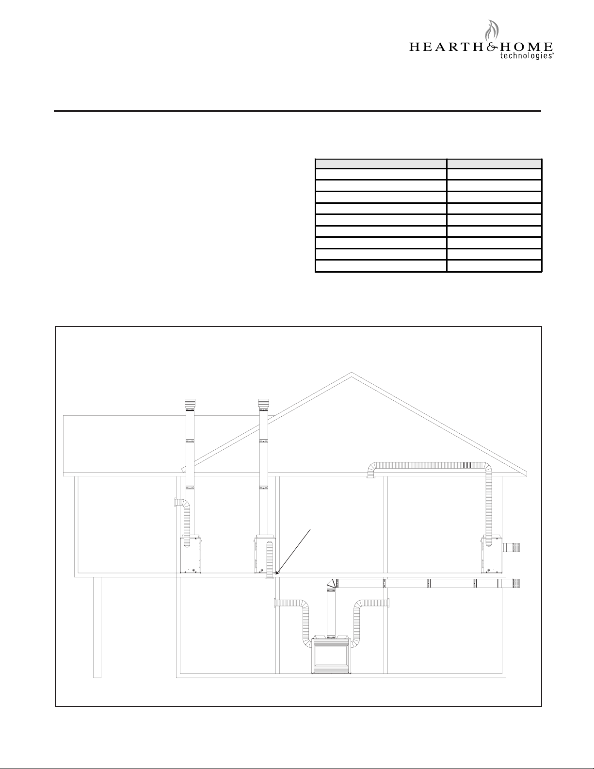
The Heat-Zone-Gas accessory kit conveys warm air
from the fireplace through air duct(s) to remote locations
in the same room or other rooms of the building. See
Figure 1. One or two Heat-Zone-Gas kits can be
installed on the fireplace.
Possible Air Duct Runs/Locations
PRELIMINARY PREPARATION
Contents of kit:
DESCRIPTION SERVICE PART NO.
20 Ft Length of 6" Round Duct 659-200
Fan Housing Assembly 659-001A
Junction Box 659-122
Variable Wall Rheostat BC10
Air Register 659-150
Register Adaptor Frame-Thick 695-125
Fireplace Duct Collar 659-125
Duct Adaptor (Round to Oval) 659-129
Hardware Bag 659-90 0 A
If any parts are missing or damaged, contact your Dealer
before starting installation. DO NOT install a damaged kit.
Be sure to also reference the fireplace Installers Guide.
Ceiling Register
Wall Register
Floor Register
Figure 1
Printed in U.S.A. Copyright 2005
Hearth & Home Technologies Inc., 20802 Kensington Boulevard, Lakeville, MN 55044
1
Two Duct Kits
659-900J 9/05
Page 2
This kit is tested and safe when installed in accordance
with this installation manual. It is your responsibility to
read all instructions before starting installation and to
follow these instructions carefully during installation.
Installation of this kit MUST be performed by a qualified
service technician.
The Heat-Zone-Gas kit is carefully engineered and must
be installed only as specified. If you modify it or any of
its components you will void the warranty, and you may
possibly cause a fire hazard. Installation must be done
according to applicable local, state, provincial, and/or
national codes.
CAUTION: All wiring should be done by a qualified
electrician and shall be in compliance with local codes
and with the National Electric Code ANSI/NFPA No. 70current (In the United States), or with the current CSC22.1
Canadian Electric Code (in Canada).
Plan the location of the fireplace and the warm air duct
run(s).
Figure 2
NOTE: If the fan housing is installed in a 2 x 4 wall, the
front of the housing will protrude approximately 1/2 - in.
(13mm) out of the wall. See Figure 3.
MAXIMUM Duct Run = 20-ft. (6.1m) for useful heat
output.
MINIMUM Duct Run = NA - for runs out from the
fireplace to adjacent room OR down to the room
below.
MINIMUM Duct Run = 31-in. (787mm) top of fireplace
to room above.
INSTALLATION
Install the Heat-Zone-Gas kit following instructions in the fireplace Installer's Guide.
FAN & ELECTRIAL CONNECTIONS
The fan and electrical connections must be accessible
for servicing per local code requirements.
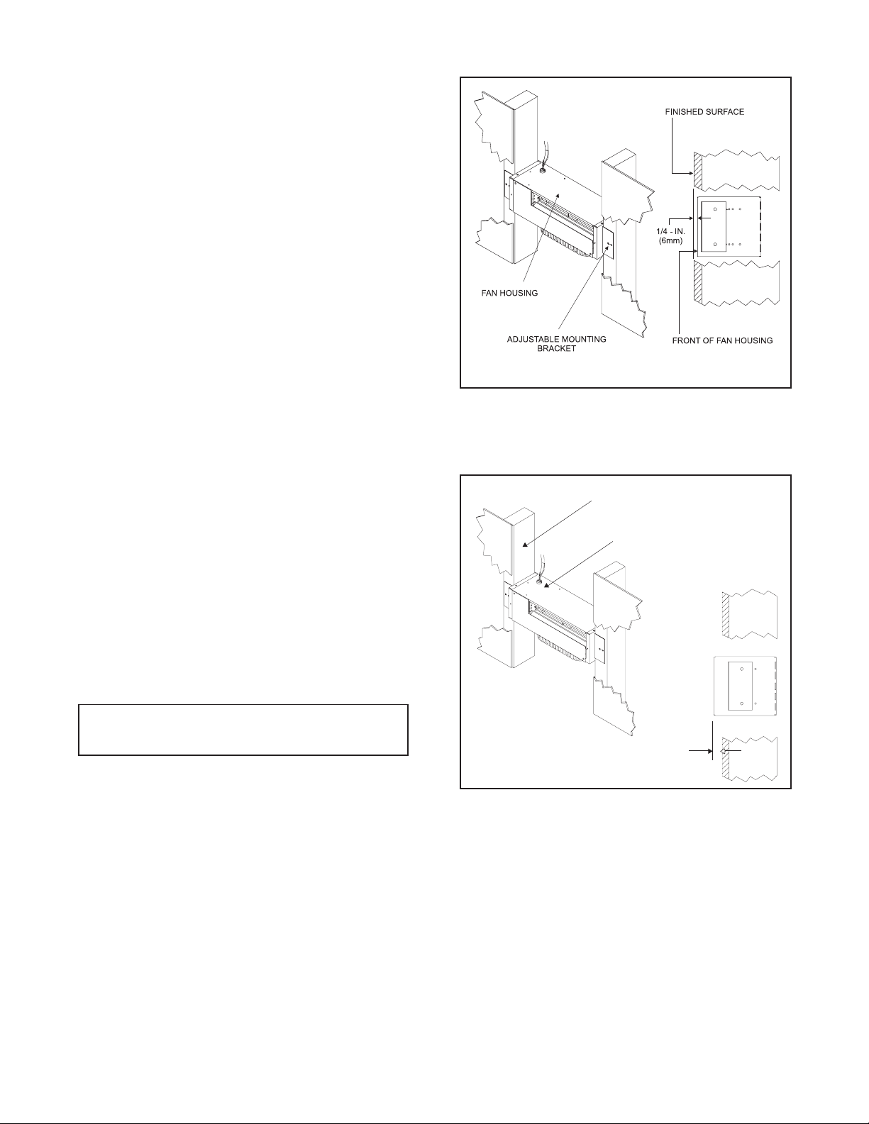
Mount and secure the fan housing assembly to framing
members so the front surface is 1/4 -in. (6mm) below
the finished wall or floor surface. Use the adjustable
mounting brackets and screws provided in the kit. See
Figure 2. NOTE: The brackets can be rotated 180o and
mounted to the back side of the 2 x 4 if necessary.
2 x 4 Wall
Fan Housing
1/2 - in.
Figure 3
(13mm)
Install the air duct run. NOTE: Fold outer poly layer of
flexible duct back to maintain clearance to combustibles on the fireplace. Secure liner to the collar with
clamp provided.
2
Page 3

V
ROUND AIR DUCT: Attach the 6" round air duct (sup-
plied in the kit) to the fireplace collar with sheet metal
screws and run the duct to the fan housing. Att ach the
round-to-oval adapter to the fan housing and the air duct
to the adapter. See Figure 4.
OV AL AIR DUCT: Attach the round-to-oval adapter to
the fireplace starting collar with sheet metal screws and
a 6" oval duct to the adapter. Complete the duct run and
attach the oval duct to the fan housing. NOTE: 6" metal
oval air duct is NOT provided with this kit but can be
purchased from an HV AC supplier.
ROUND and OV AL DUCT: A combination of 6" round and
6" oval air duct can be used in the duct run. Oval duct
components must be purchased from an HV AC supplier.
Install the variable speed (with "OFF" setting) wall Rheostat in a convenient location. This switch will control the
HEA T-ZONE-GAS fan operation.
Remove duct cover. Wire 1 10 V AC service TO the wall
Rheostat and FROM the wall Rheostat to the fan junction box. Use wire nuts to secure the 1 10 VAC service
wires to the hot and neutral fan wires and screw the
110 VAC ground wire to the fan box. See Wiring Diagram - Figure 5.
Screw the duct cover to the fan box.
Screw the register adapter frame and the air register to
the fan housing.
Support duct at intervals of no greater than four feet,
with no more than 1/2" sag between supports as required by local code. NOTE: Secure the duct so that
clearance to the fireplace outer wrap is maintained.
T ape all seams with aluminum t ape (1-1/4" minimum
width, or as specified by local codes).
Fan Housing
Round to Oval Adapter
6" Round Air Duct
Figure 5
Figure 4
USE WIRE NU TS TO
SECURE THE 110 VAC
SERVICE WIRES TO THE HOT
AND NEUTRAL FAN WIRES
Complete the fireplace installation per instructions.
OPERATION
Start the fireplace per instructions and allow it to
warm up.
Turn the wall Rheostat "ON" and adjust the variable
speed based upon desired air flow at the air duct register.
MAINTENANCE
Service and maintain the gas fireplace per instructions.
Keep the air register(s) clean and free of any blockage.
WIRE 110
AC SERVICE
FAN BOX
FAN
GROUND
SCREW
RHEOSTAT
BLACK HOT
WHITE NEUT RAL
COPPER GROUND
RHEOSTAT JUNCTION BOX
DUCT
COVER
BLACK
WHITE
GROUND
3
 Loading...