

GFK-160T Blower System
- Installation and Operating Instructions -
TM
CAUTION
DO NOT DISCARD THIS MANUAL
• Important operating and maintenance
instructions included.
• Read, understand and follow these instructions for safe installation and operation.
• Leave this manual with party responsible
for use and operation.
Note: For ease of installation install Fan Kit prior to gas
line installation.
1.0 INTRODUCTION
The GFK-160T Blower has been designed to circulate room
air through the fireplace to enhance heat output. The GFK160T blower system operates on 120 VAC, 60 Hz power.
This is available through a receptacle in the factory installed
junction box. The junction box is located in the controls compartment of the fireplace.
A variable speed control is provided with the blower system
to provide quiet forced air flow at the desired speeds. A temperature sensor switch, which automatically turns the blower
ON/OFF, is also provided with this kit.
3.0 INSTALLATION PRECAUTIONS
The GFK-160T Blower Kit is tested and safe when installed in
accordance with this installation manual. It is your responsibility to read all instructions before starting installation and to
follow these instructions carefully during installation to assure maximum benefit from, and safe operation of, the blower.
This blower is carefully engineered and must be installed
only as specified. If you modify it or any of its components,
you may cause a fire hazard and will void the WARRANTY.
In addition, such action may void the coverage provided by
the owner's home insurance.
CAUTION
All wiring should be done by a qualified electrician and
shall be in compliance with local codes and with the
National Electric Code ANSI/NFPA NO. 70-current (in
the United States), or with the current CSA C22.1 Canadian Electric Code (in Canada).
W ARNING
Do NOT wire 1 10V to valve.
• Incorrect wiring will damage this valve.
• Incorrect wiring will override IPI safety lockout
and may cause explosion.
4.0 INSTALLATION INSTRUCTIONS
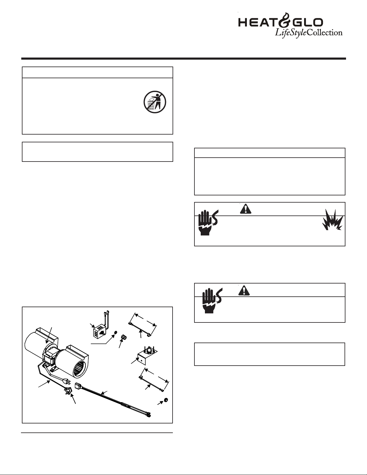
2.0 CHECK CONTENTS OF SHIPPING CARTON
Compare CONTENTS OF CARTON in Figure 1 with the actual parts received. If any parts are missing or damaged,
contact your dealer before starting installation. Do not install a damaged blower kit.
SPEED
CONTROL
GROUND
CLIP
CONTROL
NUT
CONTROL
KNOB
TEMPERATURE
SENSOR
SWITCH
CORD
BLOWER
GROUND
LEAD
FIGURE 1
Printed in U.S.A. Copyright 2005
Heat & Glo LifeStyle Collection, a brand of Hearth & Home Technologies Inc.
20802 Kensington Blvd., Lakeville, MN 55044
6’
WIRE
LEAD
WIRE
LEAD
GROMMET
6’
4.1 INSTALLING ELECTRICAL SERVICE
TO THE JUNCTION BOX
W ARNING
Shock Hazard
•
Turn electrical power off at the circuit
breaker before beginning this installation.
1. Attach a Romex clamp (not included with unit) with screws
to the outside.
NOTE: This fireplace model has a round hole through
which the service wires are fed and into which the
Romex clamp is attached.
2. Feed the 110-120 VAC electrical service wires through
the Romex clamp and secure the wires to the clamp.
3. Access the controls compartment of the fireplace to lo-
cate the Junction Box.
4. Using the wire nuts, attach the black wire to the black ser-
vice wire, the white wire to the white service wire, and the
service ground wire to the ground stud of the junction box.
5. Attach the junction box to the side of the unit. Insert the
rear tab of the box into the rectangular slot in the outer
wrap of the firebox. Push the front end of the box tightly
against the side of the unit, and secure the box with a
sheet metal screw (note the hole in the front end tab).
1
2087-023D 6/05
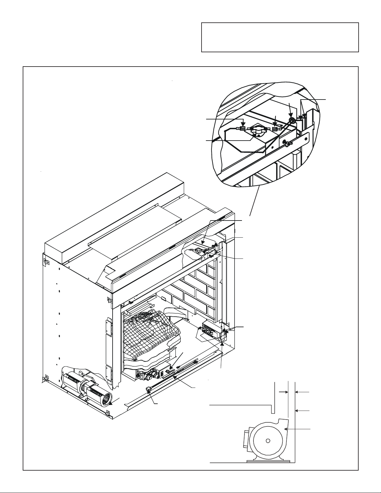
4.2 INSTALLING THE BLOWER
Position the blower all the way to the left side of the fireplace and center front to back. Pull the blower 1/8" to 1/4"
away from the side wall of the fireplace, see Figure 2.
Note: For wiring information see Figure 4. Position the
temperature switch as shown in Detail A, Figure 2. Secure in place with a screw supplied with this kit.
DET AIL A
LEAD TO
JUNCTION BOX
TEMPERATURE
SENSOR SWITCH
LEAD TO
SPEED
CONTROL
DETAIL A
GROMMET
TEMPERATURE
SENSOR SWITCH
GROMMET
LEADS DOWN
SIDE OF
FIREPLACE
FIGURE 2
BLOWER
PLUG BLOWER
INTO C ORD
ASSEMBLY
SPEED
CONTROL
ASSEMBLY
2
CORD
JUNCTION
BOX
WIRE LEADS
THROUGH SIDE
OF UNIT
1/8” TO 1/4”
FIREPLACE
WALL
BLOWER

4.3 INSTALLING THE SPEED CONTROL
AND SENSOR SWITCH
1. Remove the knob and locknut from the variable speed
control. Slide the control behind valve bracket in the front
of fireplace, with the stem sticking out of the pre-punched
hole. Att ach the locknut tightly and reattach the knob on
the stem.
2. Secure wires to sensor switch bracket.
3. Slide the temperature sensor switch/bracket assembly
onto the firebox inner top of fireplace. Secure the bracket
assembly with supplied screw, see Figure 3.
NOTE: The switch/bracket assembly must be installed
so that the sensor switch is towards the top of the unit.
SCREW
TEMPERATURE
SENSOR
SWITCH
GROMMET
GLASS
RETAINER
WING NUT (2 )
4. Connect the variable speed control and the temperature
sensor switch to the junction box with the wires provided.
For the wiring diagram see Figure 4.
5. Turn the 110-120 V AC service "ON" at the circuit breaker
and turn the speed control switch to the "ON" position.
SPEED
CONTROL
WIRE LEAD
TEMPERATURE
SENSOR
SWITCH
HOOD
FIGURE 3
FIGURE 4 Fan Wiring Diagram
BLOWER
CORD A SSEMBLY
JUNCTION BOX
NOTE: IF ANY OF THE ORIGINAL WIRE AS SUPPLIED WITH THE APPLIANCE MUST
BE REPLACED, IT MUST BE REPLACED WITH TYPE 105O C RA TED WIRE.
3
WIRE LEAD

5.0 RECOMMENDED OPERATING
PROCEDURES
Ignite the fire in the fireplace with the variable speed control
switch in an "ON" position. The fan will automatically turn
on when the temperature sensor switch closes at approximately 1 10O F . Heated air should be delivered at the outlet
grille. The fan will continue to operate after the fireplace is
turned OFF until the sensor switch opens.
V arious conditions such as type of fireplace installation and
outside air temperature vs. inside air temperature can contribute to the length of the time the blower remains on after
the fireplace is turned OFF. The blower can be turned off
manually with the speed control switch.
W ARNING
Injury Hazard
• Keep hands from blower wheel (vanes)
during blower operation.
6.0 MAINTENANCE
Periodically check the fireplace grilles and remove any dust,
dirt or obstructions.
7.0 REPLACEMENT PARTS AND CUSTOMER
SERVICE
Replacement parts and service may be obtained through
your dealer.
DESCRIPTION SERVICE PART N O.
Wire Plug Assembly 2087-026
Temp Sensor Assembly 2087-022
72" Wire Assembly 258-501A
80" Wire Assembly 522-501A
Blower 107-500A
4
 Loading...