

Page 1
Installation and Operation Instructions for the
GFK-100 BLOWER SYSTEM
1.0 INTRODUCTION
The GFK-100 Blower has been designed to circulate room air through the fireplace to enhance
heat output.
The GFK100 blower system operates on 120
V AC, 60 Hz power. This is available through a
receptacle in the factory junction box. The junction box is located in the controls compartment of the fireplace.
A variable speed control is provided with the
blower system to provide quiet forced air flow
at the desired speeds. A temperature sensor
switch, which automatically turns the blower
ON/OFF, is also provided with this kit.
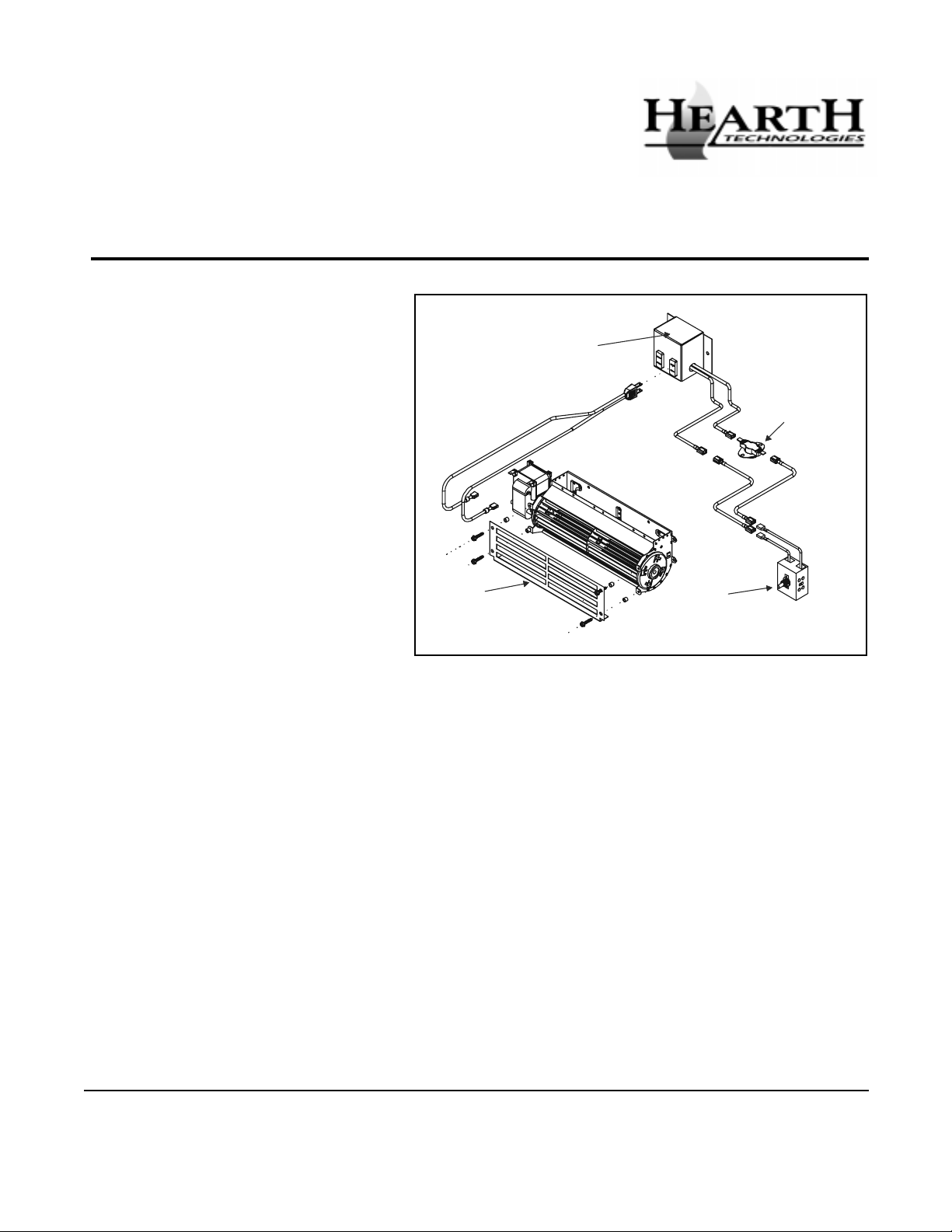
FIGURE 1
2.0 CHECK CONTENTS OF SHIPPING
CARTON
Compare CONTENTS OF CARTON in Figure 1 with the
actual parts received. If any parts are missing or damaged, contact your dealer before starting installation.
Do not install a damaged blower kit.
SAFETY
GUARD
JUNCTION BOX
TEMPERATURE
SENSOR SWITCH
SPEED CONTROL
(RHEOSTAT)
only as specified. If you modify it or any of its components, you may cause a fire hazard and will void the
WARRANTY. In addition, such action may void the coverage provided by the owner's home insurance.
3.0 INSTALLATION PRECAUTIONS
The GFK-100 Blower Kit is tested and safe when installed in accordance with this installation manual. It is
your responsibility to read all instructions before starting installation and to follow these instructions carefully
during installation to assure maximum benefit from, and
safe operation of, the blower.
This blower is carefully engineered and must be installed
Printed in U.S.A. Copyright 2001,
Hearth Technologies Inc.
20802 Kensington Boulevard, Lakeville, MN 55044, USA
CAUTION: All wiring should be done by a qualified
electrician and shall be in compliance with local codes
and with the National Electric Code ANSI/NFPA NO.
70-current (in the United States), or with the current
CSA C22.1 Canadian Electric Code (in Canada).
W ARNING: DO NOT CONNECT 110-120 VAC
WIRING TO THE GAS CONTROL VALVE OF THIS
FIREPLACE.
589-920D 7/01
1
Page 2
4.0 INSTALLA TION INSTRUCTIONS
4.2 INSTALLING THE BLOWER
4.1 INSTALLING ELECTRICAL SERVICE
TO THE JUNCTION BOX
WARNING: TURN ELECTRICAL POWER OFF AT
THE CIRCUIT BREAKER BEFORE BEGINNING
THIS INST ALLATION.
1. Attach the Romex clamp to the electrical access
hole on the right side of the fireplace. See Figure 2.
2. Feed the 110-120 VAC electrical service wires
through the Romex clamp and through the service
hole on the right side of the fireplace.
3. Access the controls compartment of the fireplace
to position the Junction Box by removing the lower
grille.
4. Using the wire nuts, attach the black wire to the
black service wire, the white wire to the white service wire, and the service ground wire to the ground
stud of the junction box.
5. From the inside attach the junction box to the right
side of the unit. Insert the rear tab of the box into
the rectangular cover plate slot, push the front end
of the box tightly against the side of the unit, and
secure the box with the hex head screw. Secure
service wires to the romex clamp.
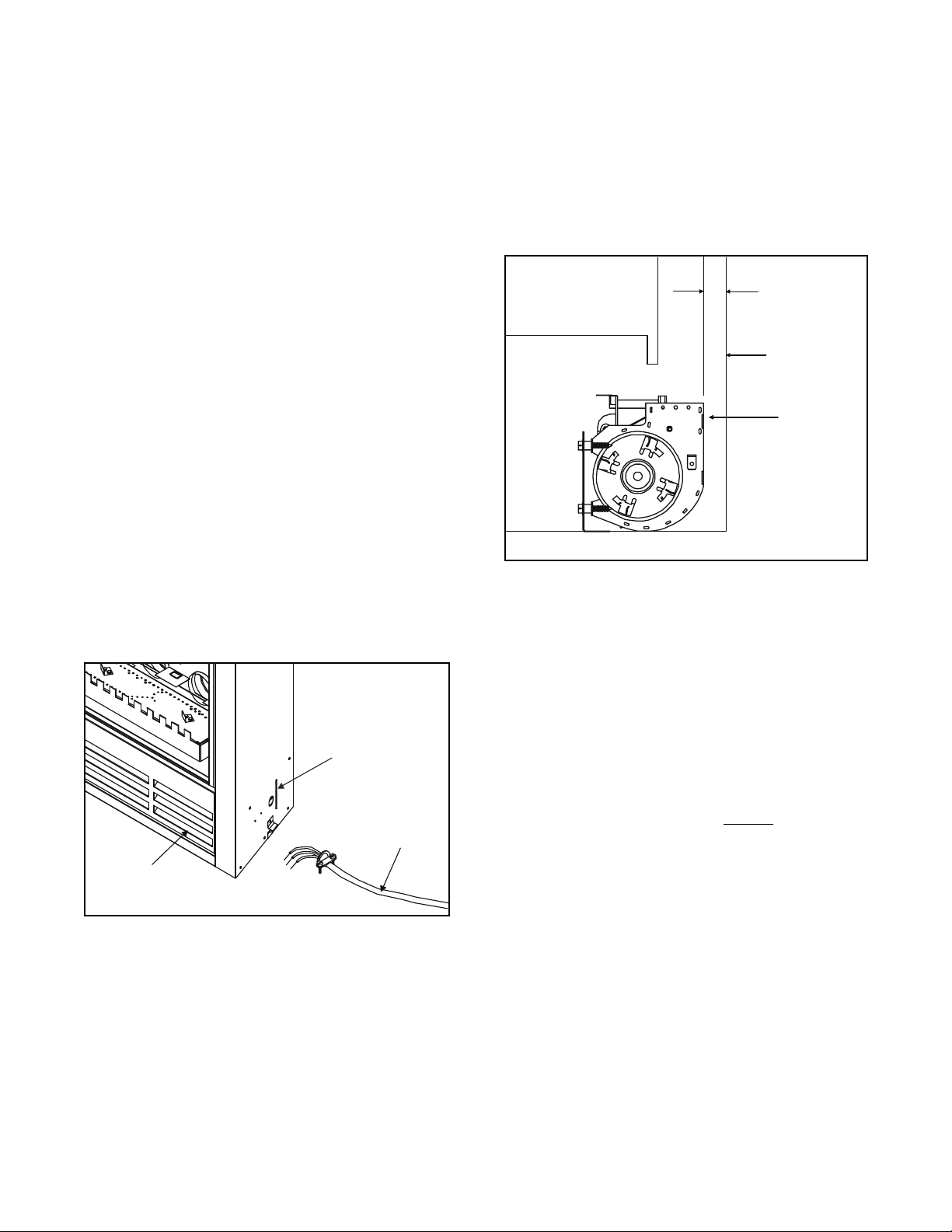
Position the blower all the way to the rear and right
hand side of the fireplace. Pull the blower forward 1/8"
to 1/ 4" from the back wall and approximately 1" from
the right wall of the fireplace (Figure 3). Plug the
blower cord into the blower receptacle marked FAN
on the junction box.
1/ 8” TO 1/4”
REAR
FIREPLACE
WALL
BLOWER
FIGURE 3
4.3 INSTALLING THE SPEED CONTROL
AND SENSOR SWITCH
LOWER
GRILLE
FIGURE 2
COVER PLATE
SLOT
110-120 VAC
1. Remove the knob and locknut from the variable
speed control. Slide the control behind the fireplace
wall, in the lower right front corner, with the stem
sticking out of the pre-punched hole. Attach the locknut tightly and reattach the knob on the stem.
2. Slide the temperature sensor switch/bracket assem-
bly onto the weld stud on the outside bottom of the
combustion chamber. Secure the bracket assembly with the wing nut provided. See Figure 4.
2
Page 3

NOTE: The weld stud is located on the bottom of the
combustion box.
TEMPERATURE
SENSOR SWITC H
WING NUT
SPEED CONTROL
5.0 RECOMMENDED OPERATING
PROCEDURES
Ignite the fire in the fireplace with the variable speed
control switch in an "ON" position. The fan will automatically turn on when the temperature sensor switch closes
at approximately 110 degrees F. Heated air should be
delivered at the outlet grille. The fan will continue to operate after the fireplace is turned OFF until the sensor
switch opens.
V arious conditions (such as fireplace model, type of fireplace installation, outside air temperature vs. inside air
temperature) can contribute to the length of the time the
blower remains on after the fireplace is turned OFF . The
blower can be turned off manually with the speed control switch.
FIGURE 4
.
NOTE: THE SWITCH/BRACKET ASSEMBLY MUST
BE INSTALLED SO THAT THE SENSOR SWITCH IS
TOWARDS THE T OP OF THE UNIT.
3. Connect the variable speed control and the temperature sensor switch to the short lead wires of the junction box by plugging in the male to female connectors. See Figure 5 - Fan Wiring Diagram.
4. Turn the 110-120 VAC service "ON" at the circuit
breaker and turn the speed control switch to the "ON"
position.
VARIABLE SPEED CONTROL
BLK
BLK
BLK
BLK
JUNCTION BOX
BLK
WARNING: NEVER CONTACT BLOWER WHEEL
(VANES) DURING BLOWER OPERATION.
6.0 MAINTENANCE
Periodically check the fireplace grilles and remove any
dust, dirt or obstructions.
7.0 REPLACEMENT PARTS
AND CUSTOMER SERVICE
Replacement parts and service may be obtained through
your dealer.
NOTE: IF ANY OF THE ORIGINAL WIRE
AS SUPPLIED WITH THE APPLIANCE
MUST BE REPLACED, IT MUST BE
REPLACED WITH TYPE 105 C RATED WIRE.
BLOWER RECEPTACLE
BLK
O
TEMPERATURE
SE NSOR SWITCH
FIGURE 5 Fan Wiring Diagram
BLK
BLK
BLK
GROUND
110-120 VAC
3
GRN
WHT
WHT
WHT
BLOWER
 Loading...