

Heat Controller B-VMH09FC-1, B-VCH18FC-1, B-VMH18FC-1, A-VCH27TC-1, B-VMH12FC-1 User Manual
...Page 1
INSTALLATION
MANUAL
Indoor Models:
B-VCH12FC-1
B-VCH18FC-1
B-VMH09FC-1
B-VMH12FC-1
B-VMH18FC-1
Version C
InverterFlex
Ductless Mini-Split Heat Pumps
High Wall and Ceiling Cassettes
Outdoor Models:
A-VCH18DC-1
A-VCH27TC-1
A-VMH36QC-1
Heat Controller, Inc. • 1900 Wellworth Ave. • Jackson, MI 49203 • (517)787-2100 • www.heatcontroller.com
Page 2
Installation Manual VMH SerieS Heat Controller, Inc.
CONTENTS
SAFETY PRECAUTIONS
Warning ...........................................................................................................................................2
Caution ............................................................................................................................................2
Nomenclature Combinations...............................................................
INSTALLATION INSTRUCTIONS
Selecting installation place...............................................................................................................3
Wall-mounted type ...........................................................................................................................3
Accessori e s ......... . . . . . . . . . . . ...................
Four-way cassette type ................................................................................................................9
Duct & Ceiling type .......................................................................................................................12
Outdoor unit installation ........................................
......... . . . . . . . . . . . ................... . . . . . . . . . . . ................4
........................................................................23
REFRIGERANT PIPE CONNECTION
Refrigerant pipe connection ..........................................................................................................24
..............................................4
ELECTRICAL WORK
Electrical work .................. ...........................................................................................................25
AIR PURGING
Air purging with vacuum pump .....................................................................................................27
Safety and leakage check ............................................................................................................29
TEST RUNNING
Test running ..................................................................................................................................30
Read This Manual
Inside you will find many helpful hints on how to install and test the air conditioner properly.
All the illustrations and specifications in the manual are subject to change without prior notice for product
improvement. The actual shape should prevail.
CAUTION
Contact an authorised service technician for repair or maintenance of this unit.
Contact an authorised installer for installation of this unit.
The air conditioner is not intended for use by young children or infirmed persons without supervision.
Young children should be supervised to ensure that they do not play with the air conditioner.
If the power cord is to be replaced, replacement work shall be performed by authorised personnel only.
Installation work must be performed in accordance with the national wiring Standards by authorised
personnel only.
2
Page 3
Heat Controller, Inc. VMH SerieS Installation Manual
SAFETY PRECAUTIONS
ead the fol low SAFETY PRECAUTIONS carefu lly before installation.
lectric al work must be installed by a licensed elect rician. Be sure to use the correct rating
f the power p lug and main circuit for the model to be instal led.
ncorrec t installation due to ignoring of the instr uction will cause harm or damage.
The serio usness is classif ied by the followin g indications.
WARNING
CAUTION
This symbol indicates the possibility of death or serious injury.
This symbol indicates the possibility of injury or damage to property.
The items to be followed are classified by the symbols:
Symbol with background white denotes item that is PROHIBITED from doing.
WARNING
1) Engage dealer or specialist for installation. If installation done by the user is defective, it will cause water
leakage, electrical shock fire.
2) Install according to this installation instructions strictly. If installation is defective, it will cause water
leakage, electrical shock fire.
3) Use the attached accessories parts and specified parts for installation. otherwise, it will cause the set to fall,
water leakage, electrical shock fire.
4) Install at a strong and firm location which is able to withstand the set s weight. If the strength is not enough
or installation is not properly done, the set will drop and cause injury.
5) For electrical work, follow the local national wiring standard, regulation and this installation instructions. An
independent circuit and single outlet must be used. If electrical circuit capacity is not enough or defect found
in electrical work, it will cause electrical shock fire.
6) Use the specified cable and connect tightly and clamp the cable so that no external force will be acted on
the terminal. If connection or fixing is not perfect, it will cause heat-up or fire at the connection.
7) Wiring routing must be properly arranged so that control board cover is fixed properly. If control board cover
is not fixed perfectly, it will cause heat-up at connection point of terminal, fire or electrical shock.
8) When carrying out piping connection, take care not to let air substances other than the specified
refrigerant go into refrigeration cycle. Otherwise, it will cause lower capacity, abnormal high pressure
in the refrigeration cycle, explosion and injury.
9) Do not modify the length of the power supply cord or use of extension cord, and do not share the
single outlet with other electrical appliances. Otherwise, it will cause fire or electrical shock.
,
CAUTION
1) This equipment must be earthed and installed with earth leakage current breaker. It may cause electrical
shock if grounding is not perfect.
2) Do not install the unit at place where leakage of flammable gas may occur. In case gas leaks and
accumulates at surrounding of the unit, it may cause fire.
3) Carry out drainage piping as mentioned in installation instructions. If drainage is not perfect, water
may enter the room and damage the furniture.
3
Page 4
Installation Manual VMH SerieS Heat Controller, Inc.
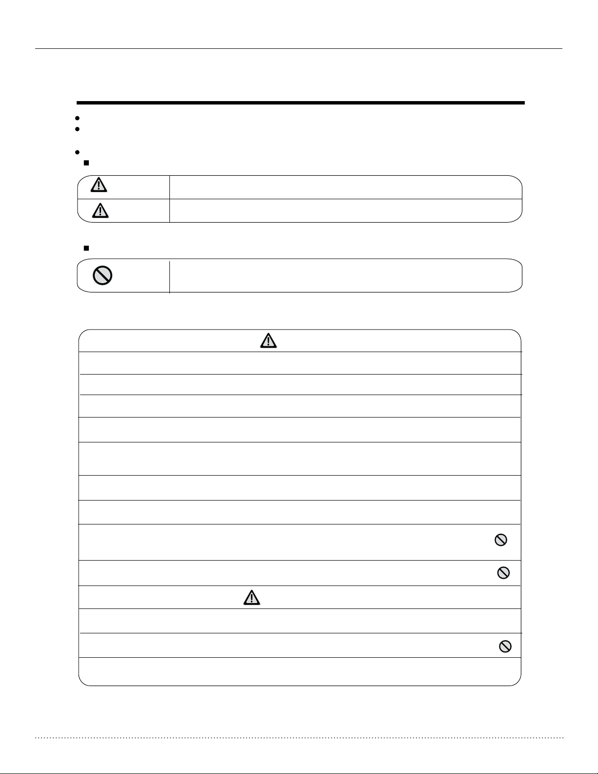
NOMENCLATURE
Outdoor Models:
A - VMH18DC - 1
Outdoor Inverter Multi-Zone
Heat
Pump
Mini-Split
Indoor Models:
B - VMH09FC - 1
Indoor Inverter Heat
M=Mini-Split
high wall
mount
C=Ceiling
cassette
Pump
Capacity
09=09kBtu/H*
12=12kBtu/H
18=18kBtu/H
*not available in
ceiling cassette
Nominal Capacity
18=18kBtu/H
27=27kBtu/H
36=36kBtu/H
Voltage Code
1=208/230V-60hz-1PH
Design
Series
D=Dual Zone
T-Tri-Zone
Q-Quad Zone
Flexible
Matching
capabilities
4
Page 5
Heat Controller, Inc. VMH SerieS Installation Manual
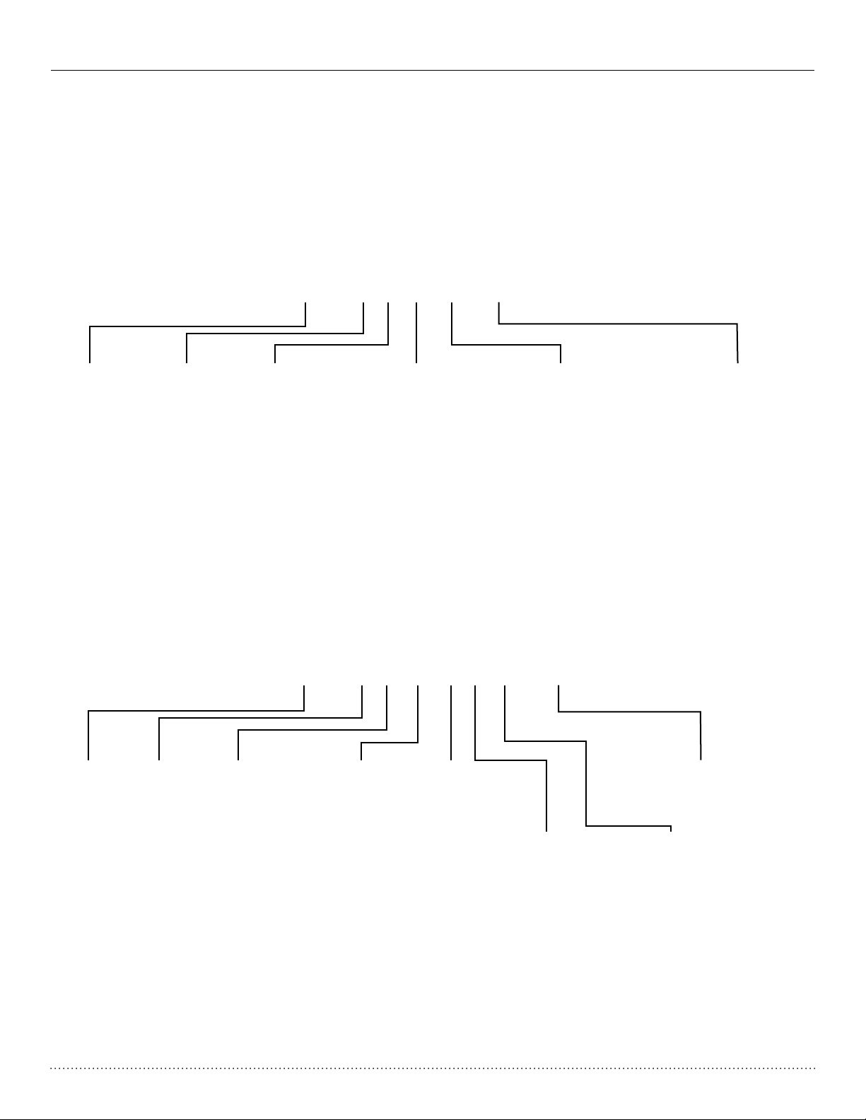
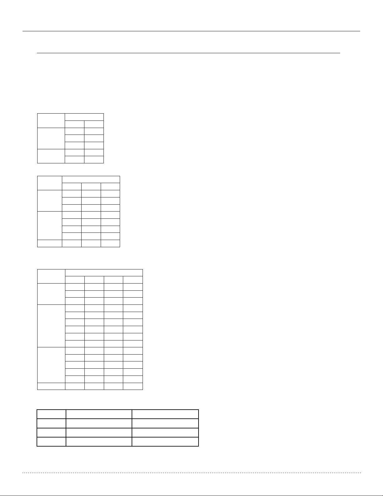
Combinations
Unit A
Unit B
9k
—
12k
—
18k
—
9k
9k
9k
12k
Combinations
Unit A
Unit B
Unit C
9k — —
12k — —
18k — —
9k
9k
—
9k
12k
—
9k
18k
—
12k
12k — TRI (1x3)
9k
9k
9k
Combinations
Unit A
Unit B
Unit C
Unit D
9k — —
—
12k — —
—
18k — —
—
9k
9k — —
9k
12k — —
9k
18k — —
12k
12k — —
12k
18k — —
18k
18k — —
9k
9k
9k
—
9k
9k
12k — 9k
9k
18k
—
9k
12k
12k
—
12k
12k
12k
—
QUA(1x4)
9k
9k
9k
9k
Unit combinations
NOTE: The total capacity of indoor air handlers can not exceed the nominal capacity of the outdoor unit.
The minimum quantity of indoor air handlers is one on any outdoor unit, whether it is a dual, tri, or quad
zone.
Indoor unit combinations for A-VMH18DC-1
Comb.
Dual(1x1)
Dual (1x2)
Indoor unit combinations for A-VMH27TC-1
Comb.
TRI (1x1)
TRI (1x2)
Indoor unit combinations for A-VMH36QC-1
Comb.
QUA (1x1)
QUA (1x2)
QUA (1x3)
Available indoor models:
High Wall Mount Ceiling Cassette
9k B-VMH09FC-1 N/A
12k B-VMH12FC-1 B-VCH12FC-1
18k B-VMH18FC-1 B-VCH18FC-1
5
Page 6
Installation Manual VMH SerieS Heat Controller, Inc.
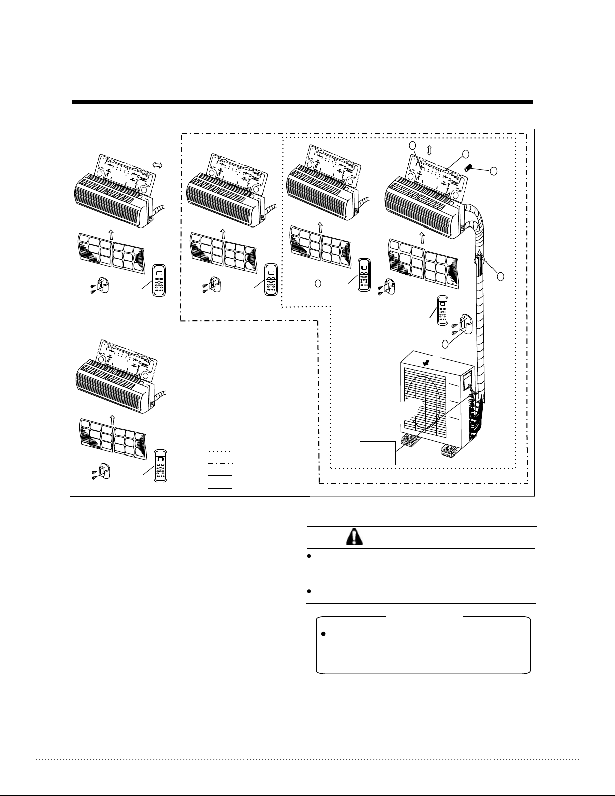
INSTALLATION INSTRUCTIONS
NOTE: Indoor units shown can be replaced with ceiling cassettes.
More th an 15 cm
More th an 12 cm
2
1
3
Air fil ter
Remot e
con troller
Air fil ter
Remot e
con troller
Air fil ter
Remot e
contr oll er
One-Two
One-Thr ee
One-Fou r
One-Fiv e
5
Remot e
con troller
Air f il ter
Loop a
conne cti ve
cable
Remot e
contr oll er
Air out
Air f il ter
4
6
CAUTIONS
This illustration is fo r explanation purposes only.
The actual shape of your ai r condtioner may be
slightl y different.
Copper li nes must be insulated independently
CAUTION
NOTE : Ceiling cas settes come w ith an
opti onal wall mou nted wirele ss thermo stat
that c an take the pla ce of the wirel ess
remo te controll er.
6
Page 7
Heat Controller, Inc. VMH SerieS Installation Manual
7. Installation Details
7.1 Wrench torque sheet for installation
Outside diameter Torque Additional tightening torque
mm inch
N.m
N.m
Ф6.35 1/4 15(153kgf.cm) 16(163kgf.cm)
Ф9.52 3/8 25(255kgf.cm) 26(265kgf.cm)
Ф12.7 1/2 35(357kgf.cm) 36(367kgf.cm)
7.2 Connecting the cables
The power wiring should always follow NEC and local codes, with respect to the unit’s, rating plate. See
installation manual for additional information. Main power connection is 208/230V/1PH~60HZ.
The communicating cable, which connects between the indoor and outdoor units must meet all NEC and
local codes, with respect to the unit’s rating plate. We recommend using 14 AWG/4 conductor Stranded THHN
6
Ф Ф V cable.
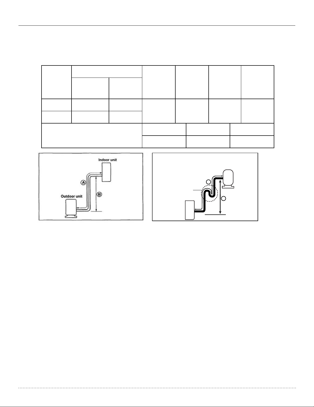
Pipe length and elevation
Pipe size
Unit
Gas inch
Liquid inch
(mm)
9K 3/8’’ (Ф9.52) 1/4’’ (Ф6.35)
12K/18K 1/2’’ (Ф12.7) 1/4’’ (Ф6.35)
Max. Total length for all rooms
(mm)
Standard
length
(m)
(5)
16.5ft
Dual-zone(m) Tri-zone(m) Quad-zone(m)
(30)100ft (45)150ft (60)200ft
Max.
Elevation
B (m)
(10)
33ft
Max.
Length
A (m)
(15)
50ft
2XWGRRUXQLW
2LOWUDS
,QGRRUXQLW
$
%
Additional
refrigerant
(g/m)
(20)
0.2 oz/ft
NOTES:
• Do not exceed 50 ft. (15m) per each indoor unit.
• Minimum pipe lenght of 10ft (3m) is required for each indoor unit.
• Oil trap should be installed per (3-5 meters) 10-15 ft., where outdoor unit is located above indoor unit.
• Outdoor connections are 1/4” (f6.35 mm) liquid and 3/8” (f9.52 mm) gas, therefore a are nut adapter
is provided with all 12/18k indoor sections.
7
Page 8
Installation Manual VMH SerieS Heat Controller, Inc.
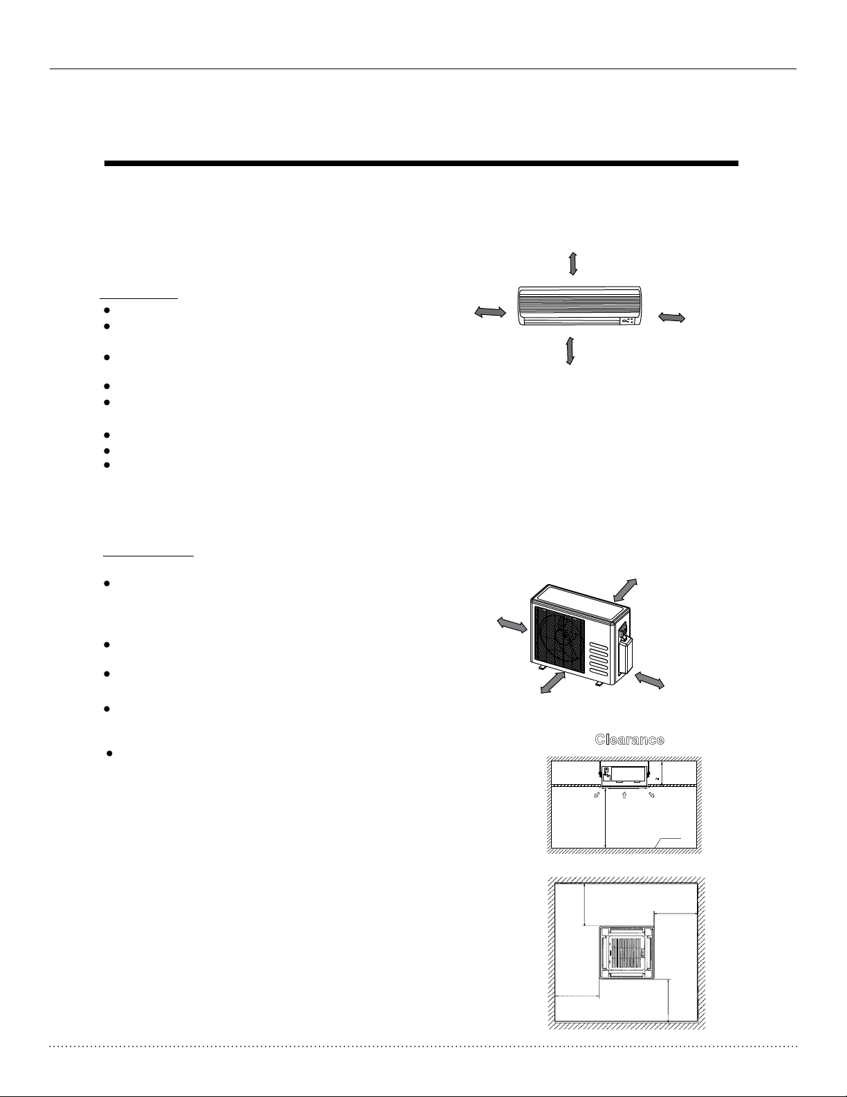
INSTALLATION INSTRUCTIONS
1. Selecting Inst allatio n Place
More than 6 in.(15cm)
Read completely, then follow step by step.
Indoor unit
More than 5 in.(12cm)
More than 5 in.(12cm)
Do not expo se the indoor unit to heat or steam .
Select a pl ace where there are no obstacles
in front or a round the unit.
Make sure t hat condensation drainage can
be conven iently routed away.
Do not inst all near a doorway.
More than 6.5 ft.(2.0m)
Fig. 1
Ensure th at the proper clearance is maintained per F ig.1.
Use a stud fi nder to locate studs to prevent u nnecessary damage to the wall.
Variati ons in pipe length may require adjustment t o refrigerant charge.
There sho uld not be any direct sunlight. Otherwise , the sun will fade the plastic cab inet and
affect its ap pearance . If unavoidable, sunlight pr eventi
on should b e taken into consideration.
Outdoor unit
More than 1 ft.(30cm)
If an awnin g is built over the outdoor unit to
prevent d irect sunlight or rain exposure,
More than 1 ft.(30cm)
make sure t hat heat radiation from the
condens er is not restricted.
Ensure th at the clearance is maintained
per Fig 2.
More than 2 ft.(60cm)
Do not plac e animals and plants in the path
of the air in let or outlet.
Take the air co nditioner weight into account
and selec t a place where noise and vibration
will not be a n issue.
More than 6.5 ft.(200cm)
Fig. 2
Clearance
Select a pl ace so that the warm air and noise from
the air con ditioner do not disturb neighbors.
Outlet
Inlet
A 11” (280mm)
Outlet
7.5ft (>2300)
Fig.13
3.5ft (>1000)
3.5ft (>1000)
Fig.14
Ground
3.5ft (>1000)
3.5 ft (>1000)
8
Page 9
Heat Controller, Inc. VMH SerieS Installation Manual
INSTALLATION INSTRUCTIONS
Tools needed for installation:
Leve l gauge
Scre wdriver
Elec tric dril l,Hole core d rill (65Ø1/4 ” mm)
Flar ing tool se t
Torq ue wrench : 1.8kgf.m, 4 .2kgf.m,
Span ner (half u nion)
Hexa gonal wre nch 1-1/2”(4mm)
Gas- leak dete ctor
Accessories for mini-split high wall mount installation
Number
1
2
3
5
6
7
Name of Accessories
Installation Plate
Dry wall anchors
Self-tapping Screw A ST3.9X25
Remote controller
Self-tapping Screw B ST2.9X10
Remote controller holder
Opti onal
part s
Vacuum pu mp
Gaug e manifol d
User s manual
Ther mometer
Mult imeter
Pipe c utter
Meas uring tap e
Q ty/one unit¡
1 (h ig h wa ll m ou nt only)
5-8
(depending o n mo de ls )
5-8
(depending o n mo de ls )
1
2
1
8
9
10
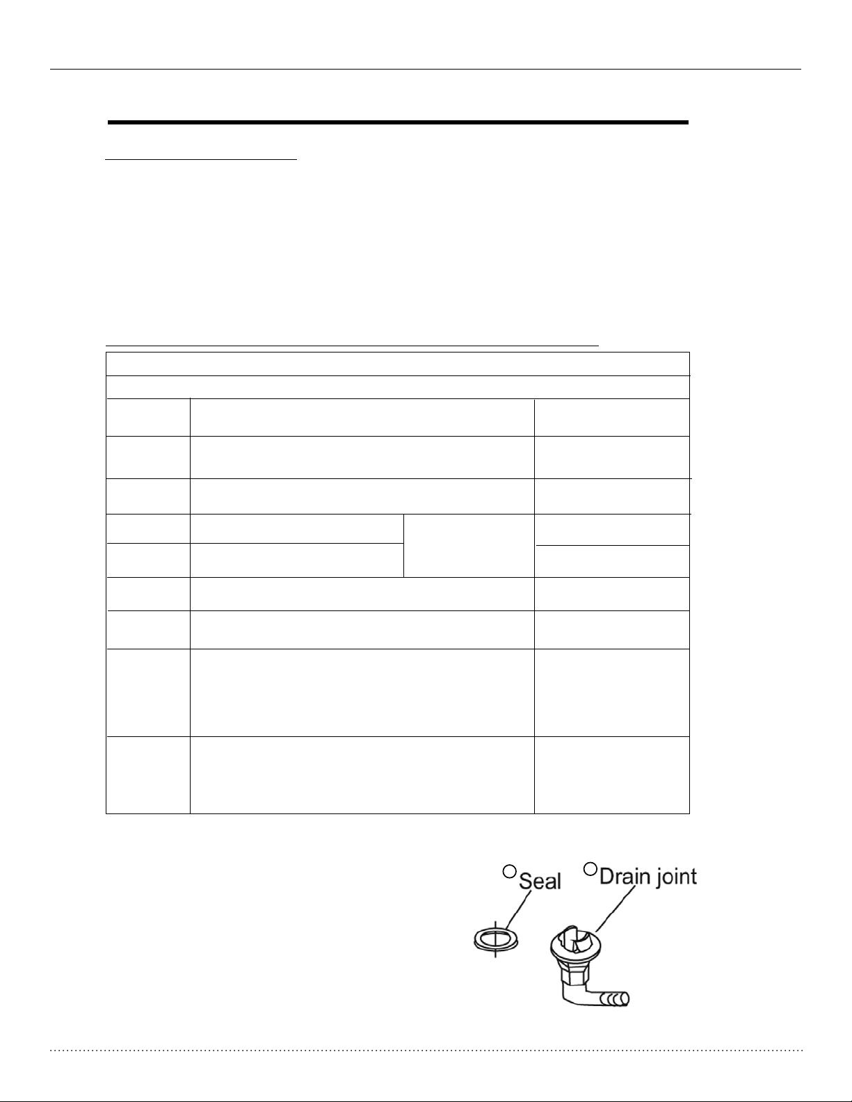
Seal (outdoor heat pumps only)
Drain Joint
(outdoor heat pumps only)
FLARE NUT ADAPTER
3/8” FFL to ½” flare nut provided w ith som e
indoor models as requir ed to make with the
1
1
1
(on some model s)
outdoor units line set.
11
FERRILE COR FILTER (clip-on)
optionally installed on the communi catio n
cable between the indoor and outdoor un it to
Optional
reduce EMI RFI noise.
No te: E xcept for t he above part s provide d, any other parts neede d during in stallation you must
purc hase.
Note: The seal and drain connector elbow are only available
with some models. Your particular product may not come with
these parts factory supplied, however they can be purchased
locally. All other parts required for installation must be purchased
separately/locally including but not limited to tools, line sets,
insulation etc.
8
9
9
Page 10

Installation Manual VMH SerieS Heat Controller, Inc.
INSTALLATION INSTRUCTIONS
Indoor unit installation(wall-mounted type)
1. Fit the Installation Plat e
1. Fit the in stallation plate horizontally
on structural parts (studs) of the wall wi th
spaces ar ound the installation plate.
2. If the wal l is made of brick, concrete
or the like , drill five or eight 3/16”(5mm )
diamete r holes in the wall.Insert Clip a nchor
for appro priate mounting screws.
3. Fit the in stallation plate on the wall
with five to eight type “A” screws.
Note:
1. Fit the Installation Plate and drill
holes in th e wall according to the
wall stru cture and corresponding
mountin g points on the in
stallat ion
plate.
2. The Installation Plate may be
slightl y different ac cording to the
different models of ind oor unit.
3. Use a stud finder to locate the studs
to preven t any unnecessary damage
to the wall .
Corre ct orie nt ati on
of Inst allat io n Pla te
Fig.4
6”(150mm) or more to ceiling
Indoor unit outline
4.75”(120mm) or
more to wall
Left rear side
refrigerant
pipe hole ¦2-9/16”(65)
Model A) A: 2 7. 95”(7 -10mm ), B :9.84 ”(250 mm ), C:3. 94”(1 00 mm), D: 4 .3 3”(110mm)
Model B ) A: 31 .10”( 790mm ), B :10.4 3”(26 5m m), C:3 .94”( 10 0mm), D : 5. 91”(1 50mm)
4.75”(120mm) or
more to wall
Left rear side
refrigerant
pipe hole ¦2-9/16”(65)
Model A) A: 2 7. 95”(7 -10mm ), B :9.84 ”(250 mm ), C:3. 94”(1 00 mm), D: 4 .3 3”(110mm)
Model B ) A: 31 .10”( 790mm ), B :10.8 3”(26 5m m), C:3 .94”( 10 0mm), D : 3. 35”(8 5mm)
Model C ) A: 33 .46”( 850mm ), B :11. 42 ”(290 mm), C: 3. 94”(1 00mm) , D: 4 .53”( 115m m)
C
Installation plate
1.75”(45)
A
6”(150mm) or more to ceiling
1.75”(45)
D
1.75”(45)
4.75”(120mm) or
more to wall
B
Right rear side
1.75”(45)
refrigerant
pipe hole ¦2-9/16”(65)
4.75”(120mm) or
more to wall
Right rear side
refrigerant
pipe hole ¦2-9/16”(65)
Model A) A: 3 6. 22”(9 20mm) , B: 11.5 4” (293m m), C:5 .9 1”(15 0mm), D : 7. 28”(1 85mm)
2. Drill a h ole in t he wall
1. Determ ine hole positions according
Model B ) A: 39 .17”( 995mm ), B :11. 54 ”(293 mm), C: 5. 91”(1 50mm) , D: 7 .87”( 200mm )
Model C ) A: 33 .46”( 850mm ), B :12.0 1”(30 5m m), C:5 .91”( 15 0mm), D : 5. 71”(1 45mm)
to the diag ram detailed in Fig.5. Drill
one (1) hol e 2-9/16”(¦65mm) slanting slightly
to outdoo r side see Fig. 6.
2. Always us e wall hole co nduit when
drillin g metal grid, metal plate or the li ke.
3. Connective Pipe and Drainage
Installation
Drainage
1. Run the drain hose sloping downward.
Do not install the drain hose as
illustrated in Fig.7.
Indoor unit outline
4.75”(120mm) or
more to wall
Left rear side
refrigerant
pipe hole ¦2-9/16”(65)
Do not block water flow by a rise.
6”(150mm) or more to ceiling
C
292
45
Installation plate
A
D
4.75”(120mm) or
more to wall
Right rear side
refrigerant
45
pipe hole ¦2-9/16”(65)
Fig. 5
Wal l
Indoo r
Fig. 6
Outdo or
3/1 6”-1/4” (5- 7mm )
Do not put the end of
drain hose into water.
Fig. 7
10
Page 11

Heat Controller, Inc. VMH SerieS Installation Manual
INSTALLATION INSTRUCTIONS
2. When connecting the drain extension hose,
insulate the connection of extension
drain hose with a shield pipe, do not let
the drain hose slack.
Connective pipe installation
1. For the left-hand and right-hand piping,
remove the pipe cover from the side
panel.
2. For the rear-right-hand and rear-left-hand
piping, install the piping as shown in Fig.10.
3. Fix the end of the connective pipe. (Refer
to Tightening Connection in REFRIGERANT
PIPING CONNECTION)
4. Piping and wrapping
Bundle the tubing, connecting cable, and drain
hose with tape securely, evenly as shown in
Fig.11.
Because the condensed water from rear of the
indoor unit is gathered in ponding box and is
piped out of room. Do not put anything else in
the box.
Right-hand piping
Left-hand piping
Fig.9
Fig.8
Rear-right piping
Rear-left piping
Fig.10
CAUTION
Connect t he indoor unit first, then the
outdoor u nit.
Do not allo w the piping to let out from
the back of t he indoor unit.
Be carefu l not to let the drain hose slack.
Heat insu late both of the auxiliary piping.
Be sure tha t the drain hose is located at
the lowes t side of the bundle. Locating
at the uppe r side can cause drain pan
to overfl ow inside the unit.
Never int ercross nor intertwine the power
wire with a ny other wiring.
Run the dra in hose sloped downward to
drain out t he condensed water smoothly.
11
Drain hose
Indoor unit
Connective
cable
Fig.11
Ponding box
Pipe room
.
.
.
.
.
.
.
.
.
.
.
.
. .
.
.
.
.
.
.
.
.
.
.
.
.
Connective
.
.
pipe
.
.
.
.
Wrapping belt
Page 12

Installation Manual VMH SerieS Heat Controller, Inc.
INSTALLATION INSTRUCTIONS
4. Indoor unit installation
1. Pass the piping through the hole in the
wall.
2. Put the upper claw at the back of the
indoor unit on the upper hook of the
installation plate, move the indoor unit
from side to side to see that it is securely
fastened (see Fig.12).
3. For easier installation separate the bottom
of the indoor unit from the wall by inserting
a spaces, such as a piece of foam between
the unit and the wall. Remove the spaces
after the piping is complete.
4. Push the lower part of the indoor unit up
on the wall, then move the indoor unit
from side to side, up and down to check
that the unit has engaged with the lower
hook of the installation plate.
Fig.12
12
Page 13

Heat Controller, Inc. VMH SerieS Installation Manual
INSTALLATION INSTRUCTIONS
2. Four-way cassette type
Included Pans
Installation Fittings
1. Expansible hook.................................4
2. Installation hook.................................4
3. Installation paper board.....................1
4. Bolt M6¡12.....................4M5¡16 or
5. Fernte Core Filter..................................1
Tubing & Fittings
6. Connecting pipe group.........................1
7. Binding tape.........................................6
8. Soundproof / insulation sheath.............2
Ceiling Cassette installation
1. Install the main body
A. The existing ceiling (to be horizontal)
a. Please cut a quadrangular hole of 600¡600mm
in the ceiling according to the shape of the
installation paper board. (Refer to Fig.15 & 16)
The center of the hole should be at the same
position of that of the air conditioner body.
Determine the lengths and outlets of the conn ecting pipe, drain pipe and cables.
To balance the ceiling and to avoid vibration,
please enforce the ceiling when necessary.
b. Please select the position of installation hooks
according to the hook holes on the installation
board.
Drill four holes of 12mm, 50~55mm deep at the
selected positions on the ceiling. Then embed
the expansible hooks(fittings).
Face the concave side of the installation hooks
toward the expansible hooks. Determine the
length of the installation hooks from the height
of ceiling, then cut off the unnecessary part.
If the ceiling is extremely high, please determine
the length of the installation hook according to
facts.
Cut the installation hook open in the middle
position, then use apropriate length of reinforcing
rod ( 12) to weld together.
Remote controller
9. Remote controller...........................1
10. Holder.............................................1
11. Mounting screw(ST2.9×10-C-H) ...2
12. Alkaline dry batteries (AM4)............2
Clearance
A 11” (280mm)
Outlet
Inlet
Outlet
A
16.61” (422)
Ground
3.5ft (>1000)
7.5ft (>2300)
Fig.13
3.5ft (>1000)
3.5ft (>1000)
Fig.14
Drain side
Wired wall mounted
controller
3.5 ft (>1000)
1” (28.5)
2.64” (67)
13
22.83” (580)(Body)
23.62” (600)(Ceiling hole)
24.06” (611)(Hook location)
25.6” (650)(Panel)
Fig.15
25.6” (650)(Panel)
22.83” (580)(Body)
23.62” (600)(Ceiling hole)
15.79” (401)(Hook location)
Page 14

Installation Manual VMH SerieS Heat Controller, Inc.
INSTALLATION INSTRUCTIONS
The length could be calculated from Fig.17:
Length=210+L(in general, L is half of the whole
length of the installation hook)
c. Please adjust the hexangular nuts on the four
installation hooks evenly, to ensure the balance
of the body.
Use the transparent hose filled with water to check
the lever of the main body from the four sides or
diagonal line direction, the lever indicator also
can check the lever from four sides of the main
body .(Refer to Fig.18)
If the drainpipe is awry, leakage will be caused
by the malfunction of the water-level switch.
Adjust the position to ensure the gaps between
the body and the four sides of ceiling are even.
The body's lower part should sink into the ceiling
for 10~12mm (Refer to Fig.17).
Locate the air conditioner firmly by wrenching the
nuts after having adjusted the body's position well.
New built houses and ceilings
a. In the case of new built house, the hook can be
embedded in advance (refer to the A.b mentioned
above). But it should be strong enough to bear the
indoor unit and will not become loose because of
concrete shrinking.
b. After installing the body, please fasten the install ation paper board onto the air conditioner with bolts
(M5¡16) to determine in advance the sizes and
positions of the hole opening on ceiling. Please
, first guarantee the flatness and horizontal of ceiling
when installing it. Refer to the A.a mentioned
above for others.
c. Refer to the A.c mentioned above for installation.
d. Remove the installation paper board.
2. Install The Panel
CAUTIONS
Never put the panel face down on floor or
against the wall, or on bulgy objects.
Never crash or strike it.
Colourless
trans parent pipe
Fixing hole
Installation
paper board
Body
Nut
Ceiling
Fig.18
Body
Screw M5¡16
(Accessory)
Ceiling
L
Horizontal
indicator
H(ceiling height)
Fig. 16
Fig.20
A
600
Fig. 17
Hook
285
Panel
10-12
Fig.19
Central hole
Hook hole
Installation
paper board
Body
176
34
(1) Remove the inlet grid.
a. Slide two grid switches toward the middle
at the same time, and then pull them up.
(Refer to Fig.21)
b. Draw the grid up to an angle of about 30 ,
and remove it. (Refer to Fig.22)
Grid switch
Fig.22
Fig.21
o
45
o
14
Page 15

Heat Controller, Inc. VMH SerieS Installation Manual
INSTALLATION INSTRUCTIONS
(2) Install the panel
a. Align the swing motor on the panel to the water
receiver of the body properly. (Refer to Fig.23)
b. Hang the four fixed rope of the main body to the
installation cover and the other three covers of
the swing motor: (Refer to Fig.23 )
CAUTIONS:
The installation cover of the swing motor must sink
into the corresponding water receiver.
c. Install the panel on the main body with bolt (M5¡16)
and washer. (Refer to Fig.23)
d. Adjust the four panel hook screws to keep the panel
horizontal, and screw them up to the ceiling evenly.
e. Regulate the panel in the direction of the arrow in
Fig.11 slightly to fit the panel's center to the center
of the ceiling's opening. Guarantee that hooks of
four corners are fixed well.
f. Keep fastening the screws under the panel hooks,
until the thickness of the sponge between the body
.
.
and the panel's outlet has been reduced to about
4~6mm. The edge of the panel should contact with
the ceiling well. (Refer to Fig.24) Malfunction
described in Fig.25 can be caused by inappropriate
tightness the screw. If the gap between the panel
and ceiling still exists after fastening the screws, the
height of the indoor unit should be modified again.
You can modify the height of the indoor unit through
the openings on the panel's four corners, if the lift of
the indoor unit and the drainpipe is not influenced
(refer to Fig.26-right).
(3) Hang the air-in grid to the panel, then connect
the lead terminator of the swing motor and that
of the control box with corresponding terminators
on the body respectively.
(4) Relocate the air-in grid in the procedure of
reversed order, install the air-in grid.
1
Steel rope
Cover
Ceiling Leakage
Dew
Panel foam2Ceiling
Panel foam
Outlet air
Drain side
Body
3
4
Air plate
Swing motor installation cover
Swing motor side
Bolt, washer
Fig.23
Inlet air
Panel
Fig.24
Fig.25
2
Panel sealing foam
Panel foam1
Hexagon nut
Horizontal adjust ment
15
Ceiling
Fig.26
Page 16
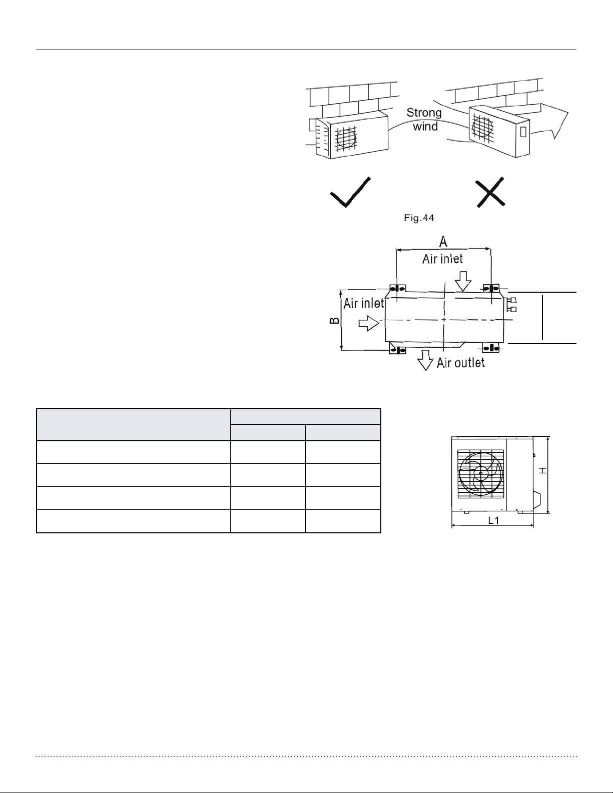
Installation Manual VMH SerieS Heat Controller, Inc.
Strong
wind
Fig.44
Outdoor Unit Installation
Outdoor installation precaution
• Install the outdoor unit on a rigid base to prevent
increasing noise level and vibration.
• Determine the air outlet direction where the
discharged air is not blocked. If the installation
place is exposed to strong winds, ensure the unit
is lengthwise along the wall or provide a suitable
air bafe.
• If suspending the unit, follow the bracket manufacturer’s instructions.
• Use a raised concrete pad or concrete blocks to
provide a solid, level surface. Securely anchor the
unit down with bolts.
• Be sure there are no obstacles which block radiating air.
• In a snowy area, install the outdoor unit on a raised
platform that is higher than drifting snow.
q
D
Anchoring outdoor unit
Anchor the outdoor unit with 5/16" (8mm) or 3/8"
(10mm) bolt and nut tightly and horizontally on a
concrete or rigid mount.
Outdoor unit dimensions
WxHxD in. (mm)
29.9 x 23.2 x 11.2 (760 x 590 x 285) 20.9 (530) 11.4 (290)
33.3 x 27.4 x 13.2 (845 x 695 x 335) 22 (560) 13.2 (335)
35.2 x 33.9 x 13.0 (895 x 860 x 330) 23.2 (590) 13.1 (333)
39.0 x 38.0 x 14.0 (990 x 965 x 355) 24.5 (623) 14.4 (366)
Mounting Dimensions
A in. (mm) B in. (mm)
q
Fig. 45
16
Page 17

Heat Controller, Inc. VMH SerieS Installation Manual
REFRIGERANT PIPE CONNECTION
Drain joint installation
Fit the seal into the drain elbow, then insert the
drain joint into the base pan hole of outdoor unit,
rotate 90 to securely assemble them.
Connecting the drain joint with an extension drain
hose (Locally purchased), in case of the water
Seal
Drain joint
Base pan hole of
outdoor unit
draining off the outdoor unit during the heating
mode.
Fig.46
Seal
Drain pipe
Refrigerant pipe connection
1. Flaring work
Main cause for refrigerant leakage
is due to defect in the flaring work.
Carry out correct flaring work
using the following procedure:
A: Cut the pipes and the cable.
1. Use the piping kit accessory or pipes
purchased locally.
2. Measure the distance between the indoor
and the outdoor unit.
3. Cut the pipes a little longer than the
measured distance.
4. Cut the cable 1.5m longer than the pipe
length.
90
Point down
Oblique
Fig.47
Pipe
Reamer
Roughness
Burr
B: Burr removal
1. Completely remove all burrs from the cut
cross section of pipe/tube.
2. Put the end of the copper tube/pipe in a
downward direction as you remove burrs in
order to avoid dropping burrs into the tubing.
C: Putting nut on
Remove flare nuts attached to indoor and
outdoor unit, then put them on pipe/tube
having completed burr removal.(not possible
to put them on after flaring work)
17
Fig.48
Flare nut
Copper tube
Fig.49
Page 18

Installation Manual VMH SerieS Heat Controller, Inc.
Refrigerant Pipe Connection
D: Flaring work
Firmly hold copper pipe in a die in the dimension shown
in the table below.
Outer diameter
in. (mm)
o 1/4" (6.35) 0.5 (1.3) 0.276 (0.7)
o 3/8" (9.35) 0.63 (1.6) 0.394 (1.0)
o 1/2" (12.7) 0.709 (1.8) 0.394 (1.0)
Tightening Connection
• Align the center of the pipes.
• Sufciently tighten the are nut with ngers, and then
tighten it with a spanner and torque wrench as shown
in Fig.51 & 52.
Outer
Diameter
o 1/4" (6.35)
o 3/8" (9.35)
o 1/2" (12.7)
Tightening
11.57 ft-lb
(160 kgf-cm)
21.69 ft-lb
(300 kgf-cm)
36.17 ft-lb
(500 kgf-cm)
Max. Min.
torque
A in. (mm)
Additional tightening
torque
14.46 ft-lb
(200 kgf-cm)
25.3 ft-lb
(350 kgf-cm)
39.78 ft-lb
(550 kgf-cm)
Caution
Excessive torque can break nut depending on
installation conditions.
18
Page 19
Heat Controller, Inc. VMH SerieS Installation Manual
ELECTRICAL WORK
Wiring connection
NOTE : Before perf orming any el ectrical
work , turn off the ma in power to the s ystem.
CAUTION
1. All wiring must comply with local and
national electrical codes
2. Unit should be grounded in compliance with
local and national electrical codes.
3. Wiring cable size and type must comply
with all applicable local and national codes.
4. Unit must have an individual branch circuit.
5. Do not touch the capacitor, even if you have
disconnected the power. A charge may remain
inside the capacitor or at least 5 minutes.
To reduce the risk of electrical shock, wait 5
minutes before doing any electrical work.
6. Turn off power supply to unit before doing any work
7. Check unit’s labels and data plates for information
regarding voltage, max fuse/HACR circuit breakers,
min. circuit ampacity.
8. Ensure all wiring is completed per the unit’s wiring
diagram. Power is supplied to the outdoor unit. The
indoor unit’s are connected to the outdoor unit
using signal wires.
Minimum norminal cross-s ectional area
of conductors:
Rated current of appliance
(A)
>3 and <6
>6 and <10
>10 and <16
>16 and <25
Nominal cross-sectional
area (mm )
2
0.75
1
1.5
2.5
Scre w
Cove r
Fig.53
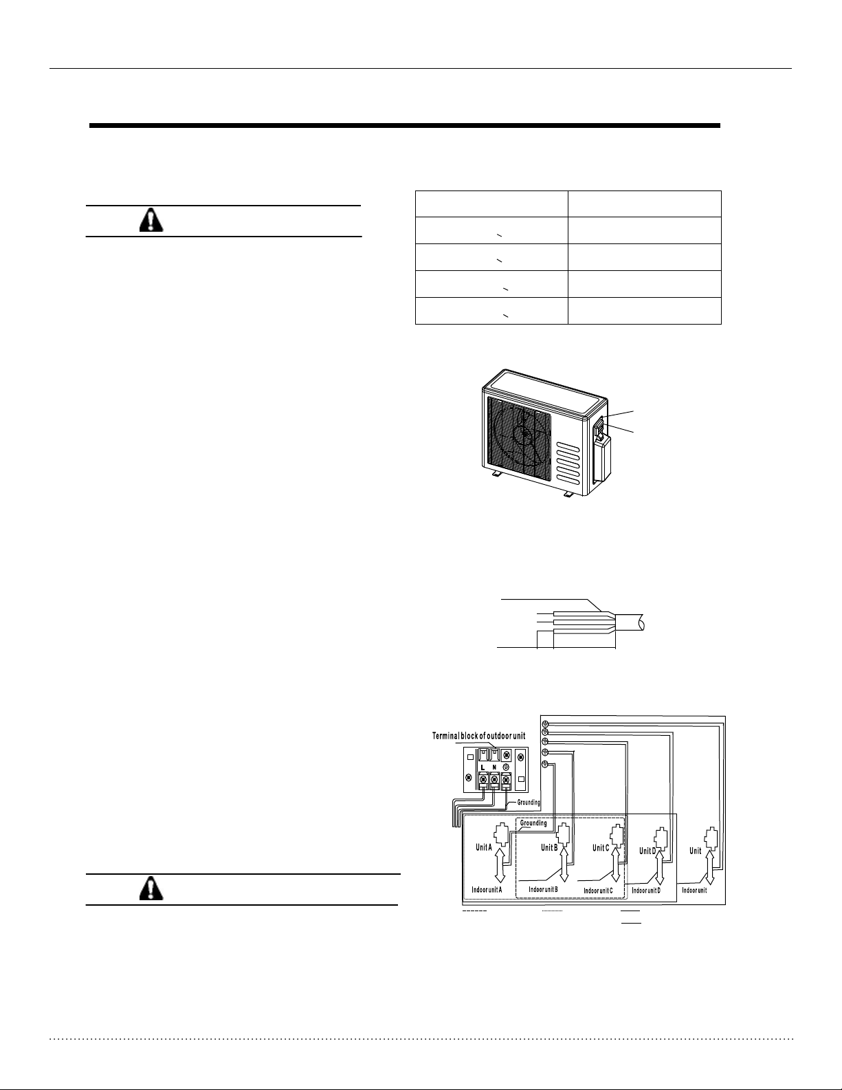
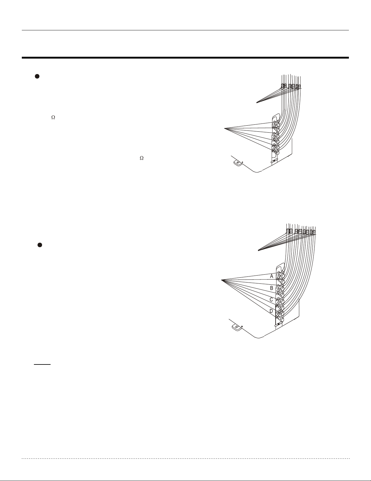
Connect the cable to the outdoor unit:
1. Remove the electrical control board cover from
the outdoor unit by loosening the appropriate
screws.
2. Connect power wires (L, N, and Ground) to the
unit’s terminal block.
3. Connect the communication cable to each indoor
unit, then to the appropriate terminal block on the
outdoor unit. Ensure that the wiring matches
between indoor and outdoor units.
4. Use the cable clamp on the outdoor unit to
prevent stress on the connections.
5. To prevent water from entering the electrical
components of the unit, form a “p” trap or loop
with the cable.
6. Insulate only unused conductors with PVC
electrical tape and ensure that they do not
touch any electrical or metal parts.
CAUTIONS
Make sure t o connect the indoor unit (A,B, C, D,
E) to the Hi an d Lo valve and terminals of signal
wires(A , B, C, D, E) of outdoor unit as identi fied
with thei r respective matched connection.
Wrong wiring connecti ons may cause some
electri cal parts to malfunction.
POWER
Connection Cable
10mm
Fig.54
Con necti ve cabl e
of in door un it and
out door un it
Con necti ve cabl e
of in door un it and
out door un it
One-two One-thr ee One-fou r
40mm
Con necti ve cabl e
of in door un it and
out door un it
Con necti ve cabl e
of in door un it and
out door un it
One-fiv e
Con necti ve cabl e
of in door un it and
out door un it
E
E
19
Page 20
Installation Manual VMH SerieS Heat Controller, Inc.
ELECTRICAL WORK
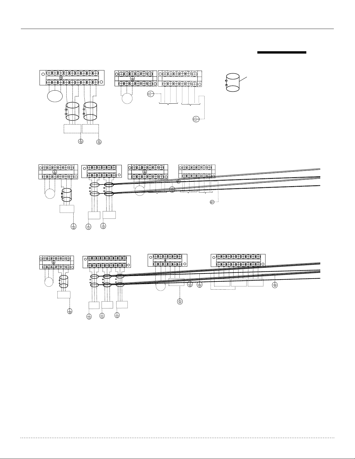
NOTE :please ref er to the follo wing figure s,if the client w ant wire by the mselves.
One-two m odels:
L(A)
N(A)
N
L
S(A)
L(B)
N(B)
POWER
TO B
TO A
Model A
One-thr ee models:
L
N
POWER
L(A)
TO A
S(A)
N(A)
L(B)
TO B
S(B)
N(B) S(B)
L(C)
N(C)
TO C
L1
POWER
SUPPLY
L2
L1
L2
L1(A)
S
L۱
L2
TO A
S(A)
S
L1(B)
L۱
TO B
L2(B)
L2
S(B)
S
L2(A)
Model B
S(C)
L2
L1
POWER
SUPPLY
L1(A)
L1
L2(A)
L2
S(A)
S
TO A
L1(B)
L1
TO B
L2(B)
L2
S(B)
S
L1(C)
L1
TO C
L2(C)
L2
S(C)
S
Model B
Ferrile Core Filter
Magnetic ring(not s up pl ie d,
optional part)
(Used to hi tch to the co nn ectiv e
cable of in door and ou td oor
units a ft er instal la tion. )
Model A
One-fou r models:
L(A)
N(A)
L
N
POWER
S(A)
TO A
Model A
L(B)
TO B
L2
L1
L1(A)
L2(A)
TO A
S(A)
Y/G
S(D)
N(D)
S(C)
L(D)
L(C)
S(B)
N(C)
N(B)
POWER
SUPPLY
Y/G
L1(B)
TO B
L2(B)
S(B)
L1(C)
TO C
L2(C)
S(C)
L1(D)
L2(D)
TO D
S(D)
Y/G
Y/G
TO D
TO C
Model B
20
Page 21

Heat Controller, Inc. VMH SerieS Installation Manual
Air Purging
Air and moisture in the refrigerant system have undesirable effects as indicated below:
• Pressure in the system rises.
• Operating current rises.
• Cooling or heating efciency drops.
• Moisture in the refrigerant circuit may freeze and block capillary tubing.
• Water may lead to corrosion of parts in the refrigeration system.
Therefore, the indoor unit and tubing between the indoor and outdoor unit must be leak tested and evacuated
to remove any noncondensables and moisture from the system.
Air purging with vacuum pump
Preparation
• Check that each tube(both liquid and gas side tubes) between the indoor and outdoor units have
been properly connected and all wiring for the test run has been completed. Remove the service
valve caps from both the gas and the liquid side on the outdoor unit. Note that both the liquid and the
gas side service valves on the outdoor unit are kept closed at this stage.
• Unit charge is located on the rating plate.
• Unit is precharged to include enough refrigerant for 16.5 ft (5m) of line set length per each indoor
unit allowed.
Example: A quad zone 36k outdoor unit will accept up to four indoor units at 16.5 ft (5m) each
for a total factory charge to handle 66 ft (20m) of total line set length.
• Charge adjustment is not required for line set lengths less than 16.5 ft. (5m).
• Add .2 oz./ft. of additional charge for line set lengths above 16.5 (5m) per indoor unit.
• The 12k and 18k indoor units include a line set adaptor for the outdoor section.
Capacity Pipe Size
Btu/H Gas (in.) Liquid (in.)
9k Indoor 3/8” 1/4”
12k Indoor 1/2” 1/4”
18k Indoor 1/2” 1/4”
Standard
Capacity Indoor Unit Length Per Maximum Total Line Length
Btu/h Combination Indoor Unit Elevation Min. Max.
18k Dual Zone (A + B) 16.5 ft. (5m) 32 ft. (10m) 10 ft. (3m) 100 ft. (30.5m)
27k Tri Zone (A + B + C) 16.5 ft. (5m) 32 ft. (10m) 10 ft. (3m) 150 ft. (45m)
36k QuadDual Zone (A + B + C) 16.5 ft. (5m) 32 ft. (10m) 10 ft. (3m) 200 ft. (60m)
21
Page 22
Installation Manual VMH SerieS Heat Controller, Inc.
Air Purging
• When relocating the unit to another place, perform evacuation
using vacuum pump.
• Make sure the refrigerant added into the air conditioner is liquid
form.
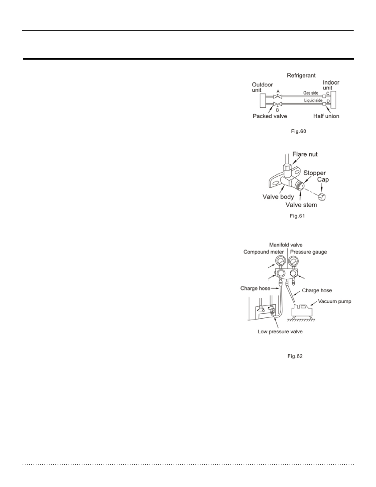
Caution in handling the packed valve
• Open the valve stem until it hits against the stop. Do not try to
open it further.
• Securely tighten the valve stem cap with a spanner or the like.
• Valve stem cap tightening torque (see tightening torque table).
When Using the Vacuum Pump
(For method of using a manifold valve, refer to its operation
manual.)
1. Completely tighten the are nuts, A, B, C, D, connect the mani-
fold valve charge hose to a charge port of the low-pressure
valve on the gas pipe side.
2. Connect the charge hose connection to the vacuum pump.
3. Fully open the Lo handle of the manifold valve.
4. Operate the vacuum pump to evacuate. After starting evacua-
tion, slightly loose theare nut of the Lo valve on the gas pipe
side and check that the air is entering(Operation noise of the
vacuum pump changes and a compound meter indicates 0
instead of minus)
5. After the evacuation is complete, fully close the Lo handle
of the manifold valve and stop the operation of the vacuum
pump. Evacuate for 15 minutes or more and check that the
compound meter indicates -29.92 inHg (-1x10⁵Pa).
6. Turn the stem of the packed valve B about 45° counterclock-
wise for 6~7 seconds after the gas comes out, then tighten the
are nut again. Make sure the pressure display in the pressure
indicator is a little higher than the atmosphere pressure.
7. Remove the charge hose from the Low pressure charge hose.
-29.92 inHg
Lo Handle
Hi Handle
8. Fully open the packed valve stems B and A.
9. Securely tighten the cap of the packed valve.
22
Page 23
Heat Controller, Inc. VMH SerieS Installation Manual
AIR PURGING
Air Purging
Safety and Leak Check
Safety and leakage check
Electrical safety check
Perform the electric safe check after
completing installation:
1. Insulated resistance
The insulated resistance must be more than
2M .
2. Grounding work
After finishing grounding work, measure the
grounding resistance by visual detection and
grounding resistance tester. Make sure the
grounding resistance is less than 4 .
3. Electrical leakage check (performing during
test run).
test running)
During test operation after finishing installation,
the serviceman can use the electroprobe and
multimeter to perform the electrical leakage
check. Turn off the unit immediately if leakage
happens. Check and find out the solution
ways till the unit operate properly.
Indoor unit
check point
Outdoor unit
check point
a,b,c,d,h,i,j , k are points for one-two type.
a,b,c,d,e,f,,h,i,j,k,m,n are points for one-three type.
Fig.63
m
n
k
j
i
h
f
A
e
d
B
c
b
C
a
Refrigerant Leak Check
Gas leak check
1. Soap water method:
Apply a soap water or a liquid neutral
Apply a soap water or a liquid neutral
detergent on the indoor unit connection
detergent on the indoor unit connection
or outdoor unit connections by a soft
or outdoor unit connections with a soft
brush to check for leakage of the
brush to check for leakage of the
connecting points of th piping. If bubbles
connecting points of th piping. If bubbles
come out, the pipes have leakage.
come out, the pipes have leakage.
2.
Leak detector
Use the leak detector to check for leakage.
CAUTION
A: Lo packed valve B: Hi packed valve
C and D are ends of indoor unit connection.
NOTE: The illustration is for explanation
NOTE: The illustration is for explanation
purposes only. The actual order of A, B, C
purpose only. The actual order of A, B, C
and D on the machine may be slightly
and D on the machine may be slightly
different from the unit you purchased. The
different from the unit you purchased. The
actual shape shall prevail.
actual shape shall prevail.
Outdoor unit
check point
Indoor unit
check point
One-four type
Fig.64
23
Page 24
Installation Manual VMH SerieS Heat Controller, Inc.
Test running
TEST RUNNING
Testing the System
Perform test operation after completing gas leak check at the flare nut connections and
electrical safety check.
Check that all tubing and wiring have been properly connected.
Check that the gas and liquid side service valves are fully open.
1. Connect the power, press the ON/OFF button on the remote controller to turn the unit on.
2. Use the MODE button to select COOL, HEAT, AUTO and FAN to check if all the functions work
2. Use the MODE button to select COOL, HEAT, AUTO and FAN to check if all the functions
well.
works well.
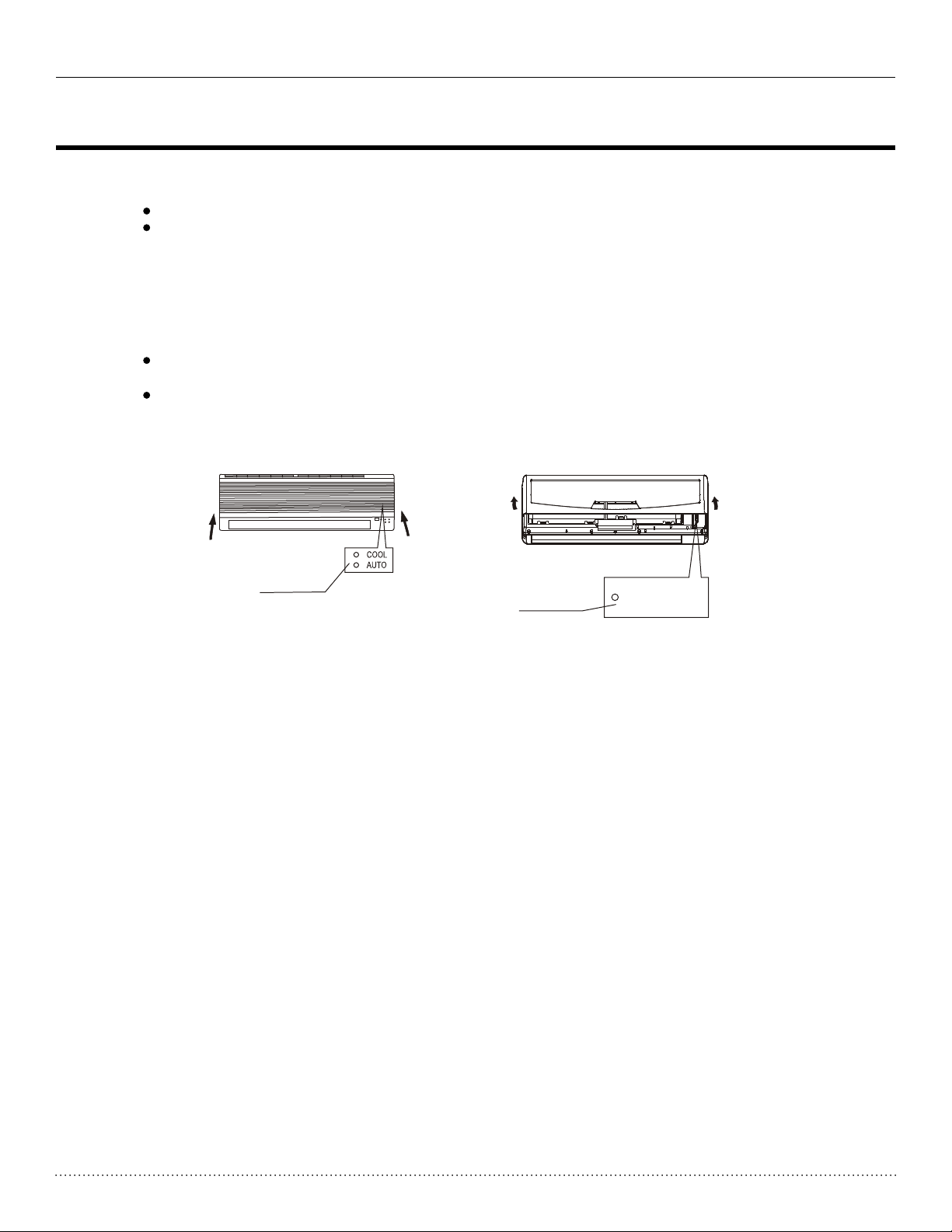
3. When the ambient temperature is too low(lower than 62.2°F (17°C)), the unit cannot be controlled
3. When the amient temperature is too low(lower than 17 C), the unit cannot be controlled by
by the remote controller to run in cooling mode, manual operation can be used. Manual opera-
the remote controller to run at cooling mode, manual operation can be taken. Manual
tion is used only when the remote controller is disable or maintenance necessary.
operation is used only when the remote controller is disable or maintenance necessary.
Hold the panel sides and lift the panel up to an angle until it remains fixed with a clicking
sound.
Press the Manual control button to select the AUTO or COOL, the unit will operate under
Forced AUTO or COOL mode(see User Manual for details).
4. The test operation should last about 30 minutes.
Manual control
Button
Fig.65
Manual control
button
AUTO/COOL
24
Page 25
Heat Controller, Inc. VMH SerieS Installation Manual
10-2012
25
 Loading...