


Heat Controller B-HMH24AS, B-HMC24AS, B-HMH18AS, B-HMC18AS, B-HMH12AS Service Manual
...®
Wall Mounted
Mini-Split System
Air Conditioning/Heat Pump
Service Manual
B/A-HMC09AS
B/A-HMC12AS, B/A-HMH12AS
B/A-HMC18AS, B/A-HMH18AS
B/A-HMC24AS, B/A-HMH24AS
Before servicing the unit, read the “safety precautions” in this manual.
Only for authorized service personnel.

Contents
Functions...................................................................................................................................... |
3 |
Product Specifications ................................................................................................................ |
5 |
Dimensions................................................................................................................................... |
7 |
Refrigeration Cycle Diagram..................................................................................................... |
10 |
Wiring Diagram .......................................................................................................................... |
12 |
Operation Details ....................................................................................................................... |
15 |
Display Function ........................................................................................................................ |
22 |
Self-diagnosis Function ............................................................................................................ |
22 |
Installation .................................................................................................................................. |
23 |
Operation .................................................................................................................................... |
38 |
Disassembly of the Parts(Indoor Unit)..................................................................................... |
40 |
Cycle Troubleshooting Guide ................................................................................................... |
46 |
Electronic Control Device ......................................................................................................... |
56 |
Schematic Diagram.................................................................................................................... |
59 |
Exploded View and Replacement Parts List............................................................................ |
60 |
- 2 -

Functions
Indoor Unit
Operation ON/OFF by Remote controller
Sensing the Room Temperature
•Room temperature sensor (THERMISTOR)
Room temperature control
•Maintains the room temperature in accordance with the Setting Temp.
Starting Current Control
•Indoor fan is delayed for 5 seconds at the starting.
Time Delay Safety Control
•Restarting is inhibited for approx. 3 minutes.
Indoor Fan Speed Control
• High, Med, Low and Auto
Operation indication Lamps (LED)
--- Lights up in operation
--- Lights up in Sleep Mode
--- Lights up in Timer Mode
--- Lights up in Defrost Mode or Hot Start Mode (only Heating Model)
OUT --- Lights up during compressor running (only Cooling Model)
DOOR
Healthy Dehumidification Mode
• Intermittent operation of fan at low speed
Sleep Mode Auto Control
•The fan is switched to low(Cooling), med(Heating) speed.
•The unit will be stopped after 1, 2, 3, 4, 5, 6, 7 hours.
Auto Air Control by the unit electronic control
•The fan is switched to intermittent or irregular operation.
•The fan speed is automatically switched from high to low speed.
Chaos Swing
•The louver can be set at the desired position or swing up and down automatically.
Defrost control(Heating)
•Both the indoor and outdoor fan stops during defrosting.
•Hot start will be operated after defrosting ends.
Hot-start Control (Heating)
•The indoor fan stops until the indoor pipe temperature will be reached at 28°C(82°F).
- 3 -

Remote Controller
Operation ON/OFF
Operation Mode Selection
(Cooling (Heating model only) model only)
Cooling Operation Mode.( |
) |
Auto Operation Mode.( |
) |
Healthy Dehumidification Operation Mode.( |
) Heating Operation Mode.( |
) |
|
Fan Speed Selection |
|
|
|
(Low) |
(Med) |
(High) |
(CHAOS) |
Room, Temperature Display |
|
|
|
: (High: 39°C(98°F) 
 LOW : 12°C(54°F)
|
|
Temperature Setting |
|
|
|
Down to 18°C(64°F) Heating |
|
Down to 16°C(60°F) |
|||
|
|
|
|
|
|
||||||
|
|
|
|
Cooling |
|
|
|||||
|
|
TEMPERATURE LOW HIGH |
|||||||||
|
|
|
|
|
|
|
|
|
|
|
|
|
|
|
|
|
|
|
|
Up to 30°C(86°F) |
|
Up to 30°C(86°F) |
|
|
|
|
|
|
|
|
|
|
|||
|
|
|
|
|
|
|
|
|
|
|
|
|
|
|
|
|
|
|
|
|
|
|
|
|
|
JET COOL |
|
|
|
|
|
|
|
|
|
|
|
|
|
|
|
|
|
|
|
|
|
Selecting ° C / ° F
° C / ° F
Setting the Time or Timer
Timer Selection
ON OFF
OFF
Timer Setting
SET
: OFF, ON, OFF 
 ON
ON
Timer Cancel
CANCEL
: Cancel Sleep Mode, Timer ON or Timer OFF
Sleep Operation
: 1, 2, 3, 4, 5, 6, 7, Off Timer
Chaos Swing
Fan Operation Mode
: Fan Operates without cooling or heating.
Horizontal Airflow Direction Control Button(Option)
Reset
- 4 -

Product Specifications(Cooling Only)
|
|
Items |
|
Unit |
B/A-HMC09AS |
B/A-HMC12AS |
B/A-HMC18AS |
B/A-HMC24AS |
Power Supply |
|
|
ø , V, Hz |
1, 115V, 60 |
1, 115, 60 |
1, 230/208, 60 |
1, 230/208, 60 |
|
Cooling Capacity |
|
|
BTU/h |
9,000 |
12,000 |
18,000/17,800 |
23,000/22,600 |
|
Input |
|
|
W |
940 |
1,290 |
1,900/1,870 |
2,550/2,500 |
|
Running Current |
|
|
A |
8.5 |
11.7 |
8.5/9.0 |
11.5/12.0 |
|
COMP. Locked Rotor AMP. |
|
A |
46 |
58 |
47 |
67 |
||
E.E.R |
|
|
BTU/hW |
9.6 |
9.3 |
9.5/9.5 |
9.0/9.0 |
|
Air Circulation |
|
|
|
m3/min(cfm) |
7.1(250) |
9.4(330) |
13(460) |
15(530) |
Moisture Removal |
|
|
|
l/h(pts/hr) |
1.2(2.6) |
1.4(3) |
2.5(5.3) |
3.1(6.6) |
Noise Level |
|
Indoor, High |
|
dB(A) |
38 |
41 |
44 |
49 |
(Sound |
|
Med |
|
dB(A) |
36 |
39 |
41 |
45 |
Pressure, 1m) |
|
Low |
|
dB(A) |
35 |
37 |
38 |
40 |
|
|
Outdoor, Max |
|
dB(A) |
48 |
48 |
55 |
57 |
Features |
|
Temperature Control |
|
|
Thermistor |
Thermistor |
Thermistor |
Thermistor |
|
|
Air Deflection |
|
|
4-way |
4-way |
4-way |
4-way |
|
|
Steps, Fan/Cool |
|
|
3/3 |
3/3 |
3/3 |
3/3 |
|
|
|
|
|
|
|
|
|
|
|
Airflow Direction Control(up&down) |
Auto |
Auto |
Auto |
Auto |
||
|
|
Airflow Direction Control(left&right) |
Manual |
Manual |
Manual |
Manual |
||
|
|
Remocon Type |
|
|
Wireless LCD |
Wireless LCD |
Wireless LCD |
Wireless LCD |
|
|
Setting Temperature Range, Cooling Mode |
64~86°F |
64~86°F |
64~86°F |
64~86°F |
||
|
|
Temperature Increment |
|
|
2°F |
2°F |
2°F |
2°F |
|
|
Auto Operation(electronic control) |
Yes |
Yes |
Yes |
Yes |
||
|
|
Self Diagnosis |
|
|
Yes |
Yes |
Yes |
Yes |
|
|
Timer |
|
|
24hr, On/Off |
24hr, On/Off |
24hr, On/Off |
24hr, On/Off |
|
|
Sleep Operation |
|
|
Yes |
Yes |
Yes |
Yes |
|
|
Healthy Dehumidification Mode |
Yes |
Yes |
Yes |
Yes |
||
|
|
Restart Delay |
|
minutes |
3 |
3 |
3 |
3 |
Refrigerant(R-22) Charge |
|
|
g(oz) |
630(22.2) |
730(25.8) |
1,250(44.1) |
2,000(70.5) |
|
|
|
|
|
|
|
|
|
|
Power cord |
|
|
AWG #: P*mm2 |
14:3*2.5 |
14:3*2.5 |
14:3*2.5 |
14:3*2.5 |
|
Fuse or breaker Capacity |
|
|
A |
15A |
20A |
20A |
25A |
|
Connecting Cable |
|
|
AWG #: P*mm2 |
16:4*0.75 |
18:4*0.75 |
18:4*0.75 |
18:4*0.75 |
|
Connecting Tube |
|
Liquid Side |
|
mm(in) |
6.35(1/4) |
6.35(1/4) |
6.35(1/4) |
9.52(3/8) |
(ø . Socket Flare) |
|
|
|
|
|
|
|
|
|
Gas Side |
|
mm(in) |
12.7(1/2) |
12.7(1/2) |
15.88(5/8) |
15.88(5/8) |
|
|
|
Length, std |
|
m(ft) |
7.62(25) |
7.62(25) |
7.62(25) |
7.62(25) |
|
|
|
|
|
|
|
|
|
Additional Drain Hose(Outer Dia.) |
|
mm(in) |
15.5(5/8) |
15.5(5/8) |
15.5(5/8) |
15.5(5/8) |
||
Dimensions |
|
Indoor |
|
mm |
802*262*165 |
888*287*170 |
1,080*314*181 |
1,080*314*181 |
(WxHxD) |
|
|
|
in |
31.6*10.3*6.5 |
35.0*11.3*6.7 |
42.5*12.4*7.1 |
42.5*12.4*7.1 |
|
|
Outdoor |
|
mm |
770*540*245 |
770*540*245 |
870*655*320 |
870*655*320 |
|
|
|
|
in |
30.3*21.3*9.6 |
30.3*21.3*9.6 |
34.3*25.8*12.6 |
34.3*25.8*12.6 |
Net Weight |
|
Indoor |
|
kg(lbs) |
7(15.4) |
9.5(20.9) |
13(28.7) |
13(28.7) |
|
|
Outdoor |
|
kg(lbs) |
32(70.5) |
32(70.5) |
61(134.5) |
62(136.7) |
|
|
|
|
|
|
|
|
|
* Design and Specifications subject to change without prior notice for product improvement.
- 5 -

Product Specifications(Cooling & Heating)
Items |
|
|
Unit |
B/A-HMH12AS |
B/A-HMH18AS |
B/A-HMH24AS |
|
Power Supply |
|
|
ø , V, Hz |
1, 115, 60 |
1, 230/208, 60 |
1, 230/208, 60 |
|
Cooling Capacity |
|
|
BTU/h |
12,000 |
18,000/17,800 |
23,000/22,600 |
|
Heating Capacity |
|
|
BTU/h |
12,000 |
19,000/18,700 |
23,000/22,600 |
|
Input |
|
Cooling |
|
W |
1,290 |
1,900/1,870 |
2,550/2,500 |
|
|
Heating |
|
W |
1,290 |
1,900/1,870 |
2,550/2,500 |
Running Current |
|
Cooling |
|
A |
11.7 |
8.5/9.0 |
11.5/12.0 |
|
|
Heating |
|
A |
11.7 |
8.5/9.0 |
11.5/12.0 |
COMP. Locked |
|
Cooling |
|
A |
58 |
42 |
67 |
Rotor AMP. |
|
Heating |
|
A |
58 |
42 |
67 |
E.E.R |
|
|
BTU/hW |
9.3 |
9.5/9.5 |
9.0/9.0 |
|
C.O.P |
|
|
|
2.75 |
2.9/2.9 |
2.6/2.6 |
|
Air Circulation |
|
|
m3/min(cfm) |
9.4(330) |
13(460) |
15(530) |
|
Moisture Removal |
|
|
l/h(pts/hr) |
1.4(3) |
2.5(5) |
3.1(6.6) |
|
Noise Level |
|
Indoor, High |
|
dB(A) |
41 |
44 |
47 |
(Sound |
|
Med |
|
dB(A) |
39 |
41 |
44 |
Pressure, 1m) |
|
Low |
|
dB(A) |
37 |
38 |
40 |
|
|
Outdoor, Max |
|
dB(A) |
48 |
55 |
58 |
Features |
|
Temperature Control |
|
Thermistor |
Thermistor |
Thermistor |
|
|
|
Air Deflection |
|
4-way |
4-way |
4-way |
|
|
|
Steps, Fan/Cool/Heat |
3/3/3 |
3/3/3 |
3/3/3 |
||
|
|
Airflow Direction Control(up&down) |
Auto |
Auto |
Auto |
||
|
|
Airflow Direction Control(left&right) |
Manual |
Manual |
Manual |
||
|
|
Remocon Type |
|
Wireless LCD |
Wireless LCD |
Wireless LCD |
|
|
|
Setting Temperature Range, Cooling Mode |
64~86°F |
64~86°F |
64~86°F |
||
|
|
Heating Mode |
|
60~86°F |
60~86°F |
60~86°F |
|
|
|
Temperature Increment |
2°F |
2°F |
2°F |
||
|
|
Auto Operation(electronic control) |
Yes |
Yes |
Yes |
||
|
|
Self Diagnosis |
|
Yes |
Yes |
Yes |
|
|
|
Timer |
|
24hr, On/Off |
24hr, On/Off |
24hr, On/Off |
|
|
|
Sleep Operation |
|
Yes |
Yes |
Yes |
|
|
|
Healthy Dehumidification Mode |
Yes |
Yes |
Yes |
||
|
|
Restart Delay |
|
minutes |
3 |
3 |
3 |
|
|
Defrost Control |
|
Yes |
Yes |
Yes |
|
|
|
Hot Start |
|
Yes |
Yes |
Yes |
|
Refrigerant(R-22) Charge |
|
|
g(oz) |
840(29.6) |
1350(47.6) |
1900(67.0) |
|
Power cord |
|
|
AWG #: P*mm2 |
14:3*2.5 |
14:3*2.5 |
14:3*2.5 |
|
Fuse or breaker Capacity |
|
|
A |
20A |
20A |
25A |
|
Connecting Cable |
|
|
AWG #: P*mm2 |
18:4*0.75 |
18:4*0.75 |
18:4*0.75 |
|
Connecting Tube |
|
Liquid Side |
|
mm(in) |
6.35(1/4) |
6.35(1/4) |
9.52(3/8) |
(ø . Socket Flare) |
|
Gas Side |
|
mm(in) |
12.7(1/2) |
15.88(5/8) |
15.88(5/8) |
|
|
Length, std |
|
m(ft) |
7.62(25) |
7.62(25) |
7.62(25) |
Additional Drain Hose(Outer Dia.) |
|
mm(in) |
15.5(5/8) |
15.5(5/8) |
15.5(5/8) |
||
Dimensions |
|
Indoor |
|
mm |
888*287*170 |
1080*314*181 |
108*314*181 |
(WxHxD) |
|
|
|
in |
35.0*11.3*6.7 |
42.5*12.4*7.1 |
42.5*12.4*7.1 |
|
|
Outdoor |
|
mm |
770*540*245 |
870*655*320 |
870*655*320 |
|
|
|
|
in |
30.3*21.3*9.6 |
34.3*25.8*12.6 |
34.3*25.8*12.6 |
Net Weight |
|
Indoor |
|
kg(lbs) |
9.5(20.9) |
13(28.7) |
13(28.7) |
|
|
Outdoor |
|
kg(lbs) |
33(72.8) |
62(136.7) |
63(138.9) |
|
|
|
|
|
|
|
|
*Design and Specifications subject to change without prior notice for product improvement.
-6 -

Dimensions
(1) Indoor Unit
D
W
H
Installation plate
Tubing hole cover
Tubing hole cover
|
MODEL |
9K |
12K |
18K, 24K |
DIM |
|
|||
|
|
|
|
|
W |
mm(inch) |
802(31.6") |
888(35.0") |
1,080(42.5") |
H |
mm(inch) |
262(10.3") |
287(11.3") |
314(12.4") |
D |
mm(inch) |
165(6.5") |
170(6.7") |
181(7.1") |
- 7 -

(2) Outdoor Unit
1. 9K, 12K |
|
|
|
W |
L2 |
L1 |
D |
|
|
L3 |
|
H
L4
Gas side (3-way valve)
L5
Liquid side (2-way valve)
|
MODEL |
9K, 12K |
|
DIM |
unit |
||
|
|||
W |
mm(inch) |
770(30.3) |
|
H |
mm(inch) |
540(21.3) |
|
D |
mm(inch) |
245(9.6) |
|
L1 |
mm(inch) |
287(11.3) |
|
L2 |
mm(inch) |
64(2.5) |
|
L3 |
mm(inch) |
518(20.4) |
|
L4 |
mm(inch) |
10(0.4) |
|
L5 |
mm(inch) |
100(3.9) |
- 8 -

2. 18K, 24K
W
D |
L1 |
L2
L3
H |
|
|
|
|
|
|
|
|
|
L9 |
Gas side |
|
|
|
|
|
|
|
|
|
|
L10 |
3-way valve |
|
|
|
|
Liquid side |
|
|
|
|
|
|
|
|
|
|
|
|
3-way valve |
L4 |
L6 |
L5 |
L7 |
L8 |
|
|
|
|
MODEL |
18K, 24K |
DIM |
|
|
|
|
|
W |
mm(inch) |
870(34.3) |
H |
mm(inch) |
655(25.8) |
D |
mm(inch) |
320(12.6) |
L1 |
mm(inch) |
370(14.6) |
L2 |
mm(inch) |
25(1.0) |
L3 |
mm(inch) |
630(24.8) |
L4 |
mm(inch) |
25(1.0) |
L5 |
mm(inch) |
546(21.5) |
L6 |
mm(inch) |
162(6.4) |
L7 |
mm(inch) |
162(6.4) |
L8 |
mm(inch) |
54(2.1) |
L9 |
mm(inch) |
74.5(2.9) |
L10 |
mm(inch) |
79(3.1) |
- 9 -

Refrigeration Cycle Diagram
• Cooling Only Models
INDOOR UNIT |
OUTDOOR UNIT |
LIQUID SIDE |
CAPILLARY TUBE |
|
HEAT |
|
|
EXCHANGER |
HEAT |
|
(EVAPORATOR) |
||
EXCHANGER |
||
|
||
|
(CONDENSER) |
|
GAS SIDE |
COMPRESSOR |
|
|
MODEL |
Pipe size(Diameter:ø) |
Piping length |
Elevation |
|
|||
|
|
|
|
|
|
|
|
Gas |
Liquid |
Rated |
Max |
Rated |
|
Max |
|
|
|
||||||
|
|
|
|
|
|
|
|
9K, 12K |
1/2" |
1/4" |
7.62m(25ft) |
15m(50ft) |
5m(16ft) |
|
8m(26ft) |
(Cooling Only) |
|
||||||
|
|
|
|
|
|
|
|
|
|
|
|
|
|
|
|
18K |
5/8" |
1/4" |
7.62m(25ft) |
15m(50ft) |
5m(16ft) |
|
8m(26ft) |
(Cooling Only) |
|
||||||
|
|
|
|
|
|
|
|
24K |
5/8" |
3/8" |
7.62m(25ft) |
15m(50ft) |
5m(16ft) |
|
8m(26ft) |
(Cooling Only) |
|
||||||
|
|
|
|
|
|
|
|
|
|
|
|
|
|
|
|
For installation over rated, *a proper quantity of refrigerant should be added for each 3.3ft(1m).
a proper quantity of refrigerant
9k, 12k |
0.7 Oz (20g) |
|
|
18k, 24k |
1.4 Oz (40g) |
|
|
Ex) 18K: When installed at a distance of 50ft(15m), 10.6Oz(295g) of refrigerant should be added. (50-25)  1.4
1.4  3.3 = 10.6 Oz (295g) of refrigerant to add
Unit precharged for 25ft. line sets.
- 10 -
• Cooling & Heating Models
INDOOR UNIT |
OUTDOOR UNIT |
LIQUID SIDE |
CAPILLARY TUBE |
CHECK VALVE |
HEAT |
HEAT |
|
EXCHANGER |
||
(EVAPORATOR) |
EXCHANGER |
|
|
(CONDENSER) |
|
GAS SIDE |
|
|
|
|
REVERSING |
|
|
VALVE |
|
COMPRESSOR |
COOLING |
|
|
HEATING |
|
Pipe size(Diameter:ø) |
Piping length |
Elevation |
|
|||
MODEL |
|
|
|
|
|
|
|
Gas |
Liquid |
Rated |
Max |
Rated |
|
Max |
|
|
|
||||||
|
|
|
|
|
|
|
|
9K, 12K |
1/2" |
1/4" |
7.62m(25ft) |
15m(50ft) |
5m(16ft) |
|
8m(26ft) |
(Cooling & Heating) |
|
||||||
|
|
|
|
|
|
|
|
|
|
|
|
|
|
|
|
18K |
5/8" |
1/4" |
7.62m(25ft) |
15m(50ft) |
5m(16ft) |
|
8m(26ft) |
(Cooling & Heating) |
|
||||||
|
|
|
|
|
|
|
|
|
|
|
|
|
|
|
|
24K |
5/8" |
3/8" |
7.62m(25ft) |
15m(50ft) |
5m(16ft) |
|
8m(26ft) |
(Cooling & Heating) |
|
||||||
|
|
|
|
|
|
|
|
For installation over rated, *a proper quantity of refrigerant should be added for each 3.3ft (1m).
a proper quantity of refrigerant
9k, 12k |
0.7 Oz (20g) |
|
|
18k, 24k |
1.4 Oz (40g) |
|
|
Ex) 18K: When installed at a distance of 50ft(15m), 10.6Oz(295g) of refrigerant should be added. (50-25)  1.4
1.4  3.3 = 10.6 Oz (295g) of refrigerant to add
Unit precharged for 25ft. line sets.
- 11 -
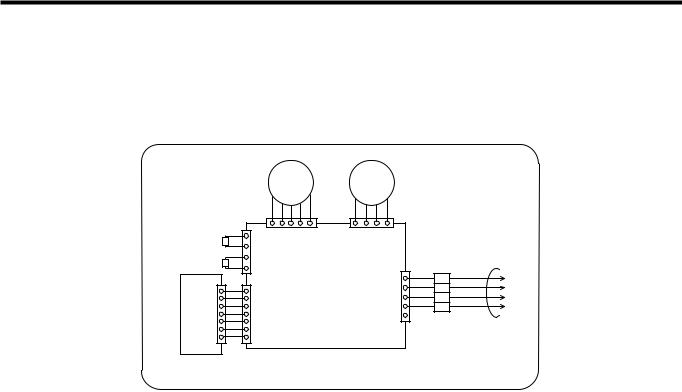
Wiring Diagram
(1)Indoor Unit
1.9K, 12K, 18K, 24K(Cooling Only Models, Cooling & Heating Models)
|
|
STEP |
BLDC |
|
|
|
|
MOTOR |
MOTOR |
|
|
(ROOM) |
|
CN-UP/DOWN |
CN-MOTOR |
|
|
TH- |
|
|
|
|
|
THERMISTOR |
|
|
|
|
|
(PIPE) |
NC |
MAIN P.C.B |
|
|
|
|
|
|
C/DCD-NC |
BL |
4 |
B.C.PDISPLAY |
|
|
BK |
||
ISPD-NC |
|
3 |
|||
|
BR |
||||
|
|
|
|
||
|
|
|
|
2 |
|
|
|
|
|
RD |
|
|
|
|
|
1 |
|
|
|
|
|
|
|
|
|
|
|
|
PILLAR |
|
|
|
|
|
TERMINAL |
INDOOR WIRING DIAGRAM |
3854AR7074A |
TO UNITOUTDOOR
- 12 -

(2) Outdoor Unit
• Cooling Only Models
1. 9K, 12K
BL |
|
MAIN P.C.B |
RD |
YL |
|
|
T/B 1 |
|
|
BR |
ZNR |
|
MOTOR |
FUSE |
|
RD |
3.15A |
RY-COMP
CN-TRANS
BL BL
BK
BK
TRANSFORMER
CAPACITOR
BR
3 |
4 |
CN-POWER |
CN-DC/DC |
|
|
F |
|
|
|
||
|
|
|
|
|
|
C |
BR |
BL |
RD BR BK BL |
|
|
|
FUSE |
|
|
|
|
|
|
|
|
|
|
H |
|
2.5A |
|
|
|
BL |
|
|
|
|
|
YL |
TERMINAL |
(N) |
(L) |
G |
|
BR |
BLOCK |
|
|
|
|
|
|
|
|
|
|
R S C |
O.L.P |
|
|
COMP. |
TO INDOOR UNIT |
||
|
|||
|
|
POWER |
|
|
|
INPUT |
|
|
OUTDOOR WIRING DIAGRAM |
3854A30077Z |
2. 18K
|
|
|
|
|
|
|
|
MAIN P.C.B |
|
|
|
|
|
OR(BR) |
|
|
|
|
|
|
|
BL |
TRANSFORMER |
||
|
|
|
|
T/B 1 |
|
|
|
|
|
|
||
|
|
YL |
BK |
|
|
|
|
|
CN-TRANS |
BL |
||
|
|
|
MOTOR |
|
|
|
|
ZNR |
|
BK |
||
|
|
|
|
|
|
|
|
|
||||
|
|
|
|
|
|
|
|
|
FUSE |
BK |
||
|
|
|
|
|
|
|
|
|
|
|||
|
|
|
|
BR |
RY-COMP |
|
3.15A |
|
|
|
||
|
|
|
|
|
|
|
|
|
|
|
||
CAPACITOR |
|
FH |
|
BR |
|
3 |
4 |
|
|
|
|
|
|
|
|
|
CN-POWER CN-DC/DC |
|
|
|
|||||
|
|
|
|
|
|
|
|
|
||||
C |
BL |
|
|
|
BR |
BL |
RD BR BK BL |
|
|
|||
|
|
|
|
FUSE |
2.5A |
|
|
|
||||
1 |
|
|
|
|
|
|
|
|||||
|
|
|
8 |
|
BR |
|
|
|
|
|
|
|
BR |
|
YL |
|
|
|
|
|
|
|
|
||
|
|
6 |
|
|
|
|
|
|
|
|
||
|
|
|
O.L.P |
|
|
|
|
|
|
|
|
|
|
S |
C |
4 |
BL |
|
|
|
|
|
|
|
|
R |
BR |
|
|
|
|
|
|
|
||||
|
|
|
0 |
2 |
|
|
TERMINAL |
|
|
|
G |
|
COMP. |
|
|
BL |
BLOCK |
|
|
|
|
||||
|
|
|
|
|
|
|
|
|||||
|
|
|
|
|
|
RD |
|
TO INDOOR UNIT |
|
|
||
|
|
|
|
|
|
|
|
POWER |
|
|||
|
|
|
OUTDOOR WIRING DIAGRAM |
|
3854AR7077J INPUT |
|
||||||
3. 24K
|
|
|
|
|
|
|
|
MAIN P.C.B |
|
|
|
|
|
OR(BR) |
|
|
|
|
|
|
|
|
BL |
TRANSFORMER |
|
|
|
|
|
T/B 1 |
|
|
|
|
|
|
||
|
|
YL |
BK |
|
|
|
|
|
CN-TRANS |
BL |
||
|
|
MOTOR |
|
|
|
|
ZNR |
|
BK |
|||
|
|
|
|
|
|
|
|
|||||
|
|
|
|
|
|
|
|
|
FUSE |
BK |
||
|
|
|
|
|
|
|
|
|
|
|||
|
|
|
|
BR |
RY-COMP |
|
3.15A |
|
|
|
||
|
|
|
|
|
|
|
|
|
||||
|
|
|
|
|
|
|
|
|
|
|
||
CAPACITOR |
|
FH |
|
BR |
|
3 |
4 |
CN-POWER CN-DC/DC |
|
|
|
|
|
|
|
|
|
|
|
||||||
|
|
|
|
|
|
|
|
|
||||
C |
BL |
|
|
|
BR |
BL |
RD BR BK BL |
|
|
|||
|
|
|
|
FUSE |
2.5A |
|
|
|
||||
1 |
|
|
|
|
|
|
|
|||||
|
|
|
8 |
|
BR |
|
|
|
|
|
|
|
BR |
|
YL |
|
|
|
|
|
|
|
|
||
|
|
6 |
|
|
|
|
|
|
|
|
||
|
|
|
|
|
|
|
|
|
|
|
|
|
R |
S |
C |
0 |
4 |
BL |
|
|
|
|
|
|
|
|
|
|
2 |
|
|
TERMINAL |
|
|
|
G |
||
COMP. |
|
|
|
BL |
BLOCK |
|
|
|
|
|||
|
|
|
|
|
|
|
|
|
||||
|
|
|
|
|
|
RD |
|
TO INDOOR UNIT |
|
|
||
|
|
|
|
|
|
|
|
POWER |
|
|||
|
|
|
OUTDOOR WIRING DIAGRAM |
|
|
|
INPUT |
|
||||
|
|
|
|
3854AR7077L |
|
|||||||
|
|
|
|
|
|
- 13 - |
|
|
|
|
|
|

• Cooling & Heating Models
1. 9K, 12K
BK |
T/B 3 |
RD |
4WAY- |
|
|
VALVE |
|
RD |
BK T/B 4 |
||
BL
RD YL
WH |
WH |
T/B 1 |
WH |
MOTOR |
T/B 2 |
|
CAPACITOR |
C |
FH |
HEATER |
|
|
|
WH |
|
|
|
CRANK |
|
|
|
CASE |
BR |
|
YL |
|
R S C BR |
RD |
||
4WAY-CN |
RY-4WAY |
MAIN P.C.B |
|
|
|
|
FAN-CN |
|
|
FUSE |
TRANS-CN |
BL |
TRANSFORMER |
RY-FAN |
|
|
BL |
|
||
|
RY-HEATER |
ZNR |
|
BK |
|
|
|
|
|
|
|
||
|
|
|
|
|
BK |
|
RY-COMP |
3.15A |
|
|
|
||
|
|
|
|
|||
3 |
4 |
CN-POWER CN-DC/DC |
|
|
|
|
BR |
RD BR BK BL |
|
|
|
|
BL |
|
|
|
|
|
|
FUSE |
|
|
|
|
|
2.5A |
|
|
|
BL |
|
|
|
|
|
|
TERMINAL |
(N) |
(L) |
G |
|
|
BLOCK |
|
|
|
|
O.L.P |
TO INDOOR UNIT |
COMP. |
|
|
POWER |
|
INPUT |
OUTDOOR WIRING DIAGRAM |
3854A30077W |
2. 18K, 24K
|
|
|
|
BK |
T/B 1 |
|
RD |
4WAY |
RY-4WAY MAIN P.C.B |
|
|
|
||||
|
|
|
|
|
|
|
|
|
|
|
|
|||||
|
|
|
|
4WAY- |
T/B 2 |
|
|
CN- |
|
|
|
|
|
|
|
|
|
|
|
|
VALVE |
|
|
|
|
|
|
|
|
|
|||
|
|
|
|
|
|
|
|
|
|
|
|
|
|
|
|
|
|
OR(BR) |
|
BK |
|
|
RD |
RY-FAN |
|
|
|
BL |
TRANSFORMER |
||||
|
|
|
|
|
|
|
|
|
|
|||||||
|
|
YL |
|
BK |
|
|
BK |
|
|
CN-TRANS |
BL |
|||||
|
|
|
|
|
|
|
|
|
|
|
|
|||||
|
|
MOTOR |
|
|
|
CN-FAN |
RY-HEATER |
ZNR |
|
BK |
||||||
|
|
|
|
|
|
|
||||||||||
|
|
|
|
WH |
|
|
|
|||||||||
|
|
|
|
WH |
|
|
|
|
|
|
|
BK |
||||
|
|
|
|
T/B 3 |
|
|
WH |
|
|
|
|
FUSE |
||||
|
|
|
|
|
|
|
|
|
|
|
||||||
|
|
|
|
|
T/B 4 |
RY-COMP |
|
3.15A |
|
|
|
|||||
|
|
|
|
|
|
|
|
|
|
|||||||
CAPACITOR |
|
FH |
|
|
WH |
|
|
|
|
3 |
4 |
CN-POWER CN-DC/DC |
|
|
|
|
C |
BL |
CRANK CASE |
BR |
|
|
|
|
RD BR BK BL |
|
|
||||||
|
|
|
BR |
BL |
|
|
||||||||||
|
HEATER |
|
|
|
|
|
|
|
||||||||
|
|
|
|
|
|
|
FUSE 2.5A |
|
|
|
||||||
|
1 |
|
|
|
|
|
|
|
|
|
|
|||||
|
|
|
|
8 |
|
BR |
|
|
|
|
|
|
|
|
|
|
BR |
|
YL |
|
|
|
|
|
|
|
|
|
|
|
|
||
|
|
|
6 |
|
|
|
|
|
|
|
|
|
|
|
||
|
|
|
|
|
|
|
|
|
|
|
|
|
|
|
|
|
R |
S |
C |
|
0 |
4 |
BL |
|
|
|
TERMINAL |
|
|
|
|
||
|
|
|
|
2 |
|
|
BL |
|
|
|
|
|
G |
|||
COMP. |
|
|
|
|
|
|
BLOCK |
|
|
|
||||||
|
|
|
|
RD |
|
|
|
|
|
|
|
|
|
|||
|
|
|
|
|
|
|
|
|
|
|
|
|
|
|
|
|
|
|
|
|
|
|
|
|
|
|
|
|
TO INDOOR UNIT |
POWER |
|
||
|
|
OUTDOOR WIRING DIAGRAM |
|
3854AR7077M |
INPUT |
|
||||||||||
|
|
|
|
|
||||||||||||
- 14 -

Operation Details
(1) The function of main control
1.Time delay Safety Control
•3min.; The compressor operation is delayed for 3 minutes to balance the pressure of cycle. (Protection of compressor)
•5sec.; The indoor fan is delayed for 5 seconds, when operating initially, to prevent noises occurred by the vertical louver and wind.
•2min.; The reversing valve is delayed for 2 minutes to prevent the refrigerant-gas for abnormal noise when the heating operation is OFF or switched to the other operation mode while compressor is off.
While compressor is running, it takes 3~5 seconds to switch.
2. Chaos Swing Mode
•By the Chaos Swing key input, the upper/lower vane automatically operates with the Chaos Swing or they are fixed to the desired direction.
•While in Chaos Swing mode, the angles of cooling and heating cycle operations are different.
< Cooling Mode > |
< Heating Mode > |
|
|
|
|
CLOSED |
CLOSED |
|
8° |
8° |
OPEN |
OPEN |
3.Cooling Operation Mode
•When selecting the Cooling(  ) Mode Operation, the unit will operate according to the setting by the remote control and the operation diagram is shown below.
INTAKE AIR TEMP.
SETTING TEMP. +1°F
(Compressor ON)
SETTING TEMP. -1°F |
|
|
|
|
|
|
(Compressor OFF) |
|
More than |
|
More than |
|
|
|
|
3 minutes |
|
3 minutes |
|
|
INDOOR FAN SPEED |
Setting |
Low |
Setting |
Low |
Setting |
|
fan speed |
fan speed |
fan speed |
||||
|
|
|
||||
COMPRESSOR |
ON |
OFF |
ON |
OFF |
ON |
■Protection of the indoor heat exchanger from frosting
•Compressor and outdoor fan stop when indoor pipe temperature is below 0°C(32°F) and restart at the pipe temperature is above 7°C(45°F).
-15 -

4.Auto Operation (Electronic control mode)
•The operation procedure is shown below. (Cooling & Heating Model)
|
|
|
|
|
|
|
|
|
|
|
|
|
|
|
|
Press Start/Stop Button |
|
|
|
|
|
|
|
|
|
|
|
|
|||
|
|
|
|
|
|
|
|
|
|
|
|
|
|
|
|
|
|
|
|
|
|
|
|
|
|
|
|
|
|
|
|
|
|
|
|
|
|
|
|
|
|
|
|
|
|
|
|
|
|
|
|
|
|
|
|
|
|
|
|
|
|
|
|
|
|
|
|
|
|
|
|
|
|
|
|
|
|
|
|
|
|
|
|
|
|
|
|
|
|
|
|
|
|
|
|
|
|
|
|
|
|
|
|
|
|
|
|
|
|
|
|
Select Auto Operation Mode |
|
|
|
|
|
|
|
|
|
||||||
|
|
|
|
|
|
|
|
|
|
|
|
|
|
|
|
|
|
|
|
|
|
|
|
|
|
|
|
|
|
|
|
|
|
|
|
|
|
|
|
|
|
|
|
|
|
|
|
|
|
|
|
|
|
|
|
|
|
|
|
|
|
||
|
|
|
|
|
|
|
|
|
|
|
|
|
|
|
|
|
|
|
|
|
|
|
|
|
|
|
|
|
|
|
|
|
|
|
|
|
|
|
|
|
|
|
|
|
|
|
|
Check the Room temperature |
|
|
|
|
|
|
|
|
|
|
|||||
|
|
|
|
|
|
|
|
|
|
|
|
|
|
|
|
|
|
|
|
|
|
|
|
|
|
|
|
|
|
|
|
|
|
|
|
|
|
|
|
|
|
|
|
|
|
|
|
|
|
|
|
|
|
|
|
|
|
|
|
|
|
|
|
|
|
|
|
|
|
|
|
|
|
|
|
|
|
|
|
|
|
|
|
|
|
|
|
|
|
|
|
|
|
|
|
|
|
|
|
|
|
|
|
|
|
|
|
|
|
|
|
|
|
|
|
|
|
|
|
|
|
|
|
|
|
|
|
|
|
|
|
Operation mode |
|
|
|
|
|
|
|
|
|
|
|
|
|
|
|
|
|
|
|
|
|
|
|
|
|
|
|
|
|
|
|
|
|
|
|
|
|
|
|
|
|
|
|
|
|
|
|
|
|
|
|
|
|
|
|
|
|
|
|
|
|
|
|
Indoor fan speed |
|
|
|
|
|
|
|
are decided automatically by the unit electronic control. |
|
|
|
|
|||||||||||||||
|
|
|
|
|
|
|
|
|
|
|
|
|
|
|
|||||||||||||||||
|
|
|
|
Setting temperature |
|
|
|
|
|
|
|
|
|
|
|
|
|
|
|
|
|
|
|
|
|||||||
|
|
|
|
|
|
|
|
|
|
|
|
|
|
|
|
|
|
|
|
|
|
|
|
||||||||
|
|
|
|
|
|
|
|
|
|
|
|
|
|
|
|
|
|
|
|
|
|
|
|
|
|
|
|
|
|
|
|
|
|
|
|
|
|
|
|
|
|
|
|
|
|
|
|
|
|
|
|
|
|
|
|
|
|
|
|
|
|
|
|
|
|
|
|
Intake-air |
|
|
|
below 70°F |
|
Over |
~ |
|
|
|
below |
|
|
|
|
Over 76°F |
|
||||||||||
|
|
|
|
temperature |
|
|
|
|
70°F |
|
|
|
76°F |
|
|
|
|
|
|||||||||||||
|
|
|
|
|
|
|
|
|
|
|
|
|
|
|
|
|
|
|
|
|
|
|
|||||||||
|
|
|
|
|
|
|
|
|
|
|
|
|
|
|
|
|
|
|
|
|
|
|
|
|
|
|
|
|
|
||
|
|
|
Operation Mode |
|
|
|
|
|
Heating |
|
Soft Dry |
|
|
|
|
|
Cooling |
|
|||||||||||||
|
|
|
|
|
|
|
|
|
|
|
|
|
|
|
|
|
|
|
|
|
|
|
|
|
|
||||||
|
|
|
If initial mode is decided, that mode is continued without the room temperature changing. |
|
|||||||||||||||||||||||||||
|
|
|
■ Auto Operation for Cooling |
|
|
|
|
|
|
|
|
|
|
|
|
|
|
||||||||||||||
|
|
|
|
|
|
|
|
|
|
|
|
|
|
|
|
|
|
|
|
|
|||||||||||
|
|
|
Operation Condition |
|
|
|
|
Intake-air Temperature |
Setting Temperature |
|
|
|
Fan Speed |
|
Air Direction Control |
|
|||||||||||||||
|
|
|
|
|
|
|
|
|
|
|
|
|
|
|
|
|
|
|
|
|
|
|
|
|
|
|
|
|
|||
|
|
|
|
|
|
|
|
|
|
|
|
|
|
|
|
|
|
|
|
|
|
|
|
|
|
|
|
|
|
|
|
|
|
|
|
|
|
|
|
|
|
|
|
|
|
Over 78°F |
|
77°F |
|
|
|
|
|
|
|
|
|
|
|
|
|||
|
|
|
|
|
|
|
|
|
|
|
|
|
|
|
|
|
|
|
|
|
|
|
|
|
|
|
|||||
|
|
|
|
|
|
|
|
|
|
|
|
|
|
|
|
|
|
|
|
|
|
|
|
|
|
|
|||||
|
|
|
|
|
|
|
|
|
|
|
|
Over 76°F~below 78°F |
|
Intake air -1°C |
|
|
|
|
|
|
|
|
|
In this mode, |
|
|
|||||
|
|
|
|
|
|
|
|
|
|
|
|
|
|
|
|
|
|
|
|
|
|
|
|
|
|
|
|
|
|
|
|
|
|
|
When Auto Operation |
|
|
|
|
|
|
|
|
|
|
|
|
|
|
|
|
|
|
|
|
|
|
||||||
|
|
|
|
|
|
Over 72°F~below 76°F |
Intake air -0.5°C |
|
|
|
|
|
|
when pressing |
|
|
|||||||||||||||
|
|
|
initial start |
|
|
|
|
|
|
|
|
|
|
|
|
|
|
|
|
|
|
|
|
the vertical air |
|
|
|||||
|
|
|
|
|
|
|
|
|
|
|
|
|
|
|
|
|
|
Controlled by |
|
|
|
|
|||||||||
|
|
Over 68°F~below 72°F |
Intake air temperature |
|
|
|
|
|
|
|
|||||||||||||||||||||
|
|
|
|
|
|
|
|
|
|
|
|
|
|
|
|
|
|
direction control |
|
|
|||||||||||
|
|
|
|
|
|
|
|
|
|
|
|
|
|
|
|
|
|
|
|||||||||||||
|
|
|
|
|
|
|
|
|
|
|
|
|
the electronic |
|
|
|
|
|
|||||||||||||
|
|
|
|
|
|
|
|
|
|
|
|
|
|
|
|
|
|
|
|
|
|
|
|
|
|
|
button, vertical |
|
|
||
|
|
|
|
|
|
|
|
|
|
|
|
|
|
below 64°F |
|
64°F |
|
|
|
|
control |
|
|
|
|
|
|||||
|
|
|
|
|
|
|
|
|
|
|
|
|
|
|
|
|
|
|
|
|
|
louver swings up |
|
|
|||||||
|
|
|
|
|
|
|
|
|
|
|
|
|
|
|
|
|
|
|
|
|
|
|
|
|
|
|
|
|
|
|
|
|
|
|
|
|
|
|
|
|
|
|
|
|
|
|
|
|
|
|
|
|
|
|
|
|
|
|
|
|
|
||
|
|
|
|
|
|
|
|
|
|
|
|
|
and down |
|
|
||||||||||||||||
|
|
|
|
|
|
|
|
|
|
|
|
|
|
|
|
||||||||||||||||
|
|
When pressing room |
|
|
Over 64°F~below 86°F |
Electronic control |
|
|
|
|
|
|
|
|
|
|
|||||||||||||||
|
|
temperature setting |
|
|
|
|
|
|
|
|
|
|
|
|
|
|
|
|
|
|
|
automatically. |
|
|
|||||||
|
|
|
|
below 64°F |
|
64°F |
|
|
|
|
|
|
|
|
|
|
|||||||||||||||
|
|
button during Auto |
|
|
|
|
|
|
|
|
|
|
|
|
|
|
|
|
|
||||||||||||
|
|
|
|
|
|
|
|
|
|
|
|
|
|
|
|
|
|
|
|
|
|
|
|
||||||||
|
|
Operation |
|
|
|
|
over 86°F |
|
86°F |
|
|
|
|
|
|
|
|
|
|
|
|
||||||||||
|
|
|
|
|
|
|
|
|
|
|
|
|
|
|
|
|
|
|
|
|
|
|
|
|
|
|
|||||
|
|
|
|
|
|
|
|
|
|
|
|
|
|
|
|
|
|
|
|
|
|
|
|
|
|
|
|
|
|
|
|
|
|
|
|
|
|
|
|
|
|
|
|
|
|
|
|
|
|
|
|
|
|
|
|
|
|
|
|
|
|
|
|
|
|
|
|
|
|
|
|
|
|
|
|
|
|
|
|
|
|
|
|
|
|
|
|
|
|
|
|
|
|||
|
|
|
INTAKE AIR TEMP. |
|
|
|
|
|
|
|
|
|
|
|
|
|
|
|
|
|
|
|
|
|
|
|
|||||
|
|
SETTING TEMP. +1°F |
|
|
|
|
|
|
|
|
|
|
|
|
|
|
|
|
|
|
|
|
|
|
|
||||||
|
|
|
|
|
|
|
|
|
|
|
|
|
|
|
|
|
|
|
|
|
|
|
|
||||||||
|
|
(Compressor OFF) |
|
|
|
|
|
|
|
|
|
|
|
|
|
|
|
|
|
|
|
|
|
|
|
||||||
|
|
|
SETTING TEMP. -1°F |
|
|
|
|
|
|
|
|
|
|
|
|
|
|
|
|
|
|
|
|
|
|
|
|||||
|
|
|
|
|
|
|
|
|
|
|
|
|
|
|
|
|
|
|
|
|
|
|
|
||||||||
|
|
|
(Compressor ON) |
|
|
|
|
|
|
|
|
|
|
|
|
|
|
|
|
|
|
|
|
|
|
|
|||||
|
|
|
|
|
|
|
|
|
|
|
|
|
|
|
|
|
|
|
|
|
|
|
|
||||||||
|
INDOOR FAN SPEED |
|
|
|
|
|
|
|
|
|
The electronic control operation |
|
|
|
|
||||||||||||||||
|
|
|
|
|
|
|
|
|
|
|
|
|
|
|
|
|
|
|
|
|
|
|
|
|
|
||||||
|
COMPRESSOR |
|
|
|
|
|
ON |
|
|
OFF |
|
|
|
|
ON |
|
OFF |
|
|||||||||||||
|
|
|
|
|
|
|
|
|
|
|
|
|
|
|
|
|
|
|
|
|
|
|
|
|
|
|
|
|
|
|
|
- 16 -
■ Auto Operation for Dehumidification(only Heating Model)
•The Setting temperature will be same that of the auto operation for cooling.
-Compressor ON temperature; Setting temperature +2°F
-Compressor OFF temperature; Setting temperture -1°F
Intake-air temp. |
below 68°F |
Over 68°F~below 70°F |
over 86°F |
|
|
|
|
Setting temp. |
68°F |
Intake air temperature +1°F |
86°F |
|
|
|
|
■ Auto Operation for Heating(only Heating Model)
-Compressor ON temperature; Setting temperature
-Compressor OFF temperature; Setting temperature +6°F
■Vertical louver auto operation : During Auto Operation, pressing the chaos swing button makes the horizontal louvers swing up and down automatically.
If you want to stop auto-swing, press chaos swing button again.
- 17 -
5.Healthy Dehumidification
•When the dehumidification operation input by the remote control is received, the intake air temperature is detected and the setting temp is automatically set according to the intake air temperature.
26°C ≤ |
Intake Air Temp |
25°C |
24°C ≤ |
Intake Intake Air Temp<26°C |
Intake Air Temp-1°C |
18°C ≤ |
Intake Intake Air Temp<24°C |
Intake Air Temp-0.5°C |
Intake Air Temp<18°C |
18°C |
|
•While in compressor off, the indoor fan repeats low airflow speed and pause.
•While the intake air temp is between compressor on temp. and compressor off temp., 10-min dehumidification operation and 4-min compressor off repeat.
Compressor ON Temp. Setting Temp+0.5°C Compressor OFF Temp. Setting Temp-0.5°C
•In 10-min dehumidification operation, the indoor fan operates with the low airflow speed.
- 18 -

6. Heating Operation Mode(only Heating Model)
The unit will operate according to the setting conditions by the remote controller.
The operation diagram is shown below.
INTAKE AIR TEMP. |
|
|
|
|
|
|
|
|
SETTING TEMP. +6°F |
|
|
|
|
|
|
|
|
(Compressor OFF) |
|
|
|
|
|
|
|
|
|
|
|
A |
B |
|
|
A |
|
|
|
|
|
|
|
|||
|
|
|
|
|
|
|
||
SETTING TEMP. |
|
|
|
|
|
|
|
|
(Compressor ON) |
|
minimum |
|
minimum |
|
minimum |
|
|
|
|
10sec. |
|
1 min. |
|
10sec. |
|
|
INDOOR FAN SPEED |
Selecting |
Low |
OFF |
Low |
Selecting |
Low |
OFF |
|
fan speed |
fan speed |
|||||||
|
|
|
|
|
|
|||
COMPRESSOR |
ON |
|
OFF |
|
ON |
|
OFF |
•A point; While the indoor pipe temperature is higher than 95°F, indoor fan operates at low speed. When the indoor pipe temperature becomes lower than 95°F, indoor fan stops.
•B point; When the indoor pipe temperature is higher than 38°C(100°F), fan operates at selected fan speed.
■Hot-Start Control
•The indoor fan stops until the indoor pipe temperature will be reached at 82°F.
•During heating operation, if indoor pipe temperature falls below 78°F fan stops.
•The operation diagram is shown below.
INDOOR PIPE |
|
1min |
|
|
|
TEMP. |
|
|
|
|
|
|
|
|
|
|
|
82°F |
|
|
|
|
|
|
|
|
|
|
|
78°F |
|
|
|
|
|
|
|
|
|
|
|
|
|
|
|
|
|
INDOOR FAN SPEED |
OFF |
LOW |
|
Selecting |
OFF |
|
fan speed |
||||
|
|
|
|
|
|
COMPRESSOR |
|
|
ON |
|
|
|
|
|
|
|
|
- 19 -

7.Cooling or Heating Mode with Sleep Mode Auto Control
•When selecting the Cooling(  ) or the Heating(
  ) combined with the Sleep Mode Auto Control(
 ), the operation diagram is as following.
■Cooling Mode with the Sleep Mode
•The setting temperature will be automatically raised by 2°F 30 minutes later and by 4°F 1 hour later.
•The operation will be stopped after 1, 2, 3, 4, 5, 6, 7 hours.
INTAKE AIR TEMP. |
|
30 minutes |
|
|
30 minutes |
|
|
|
|
2°F |
|
|
|
|
|
|
|
SETTING TEMP. +1°F |
|
|
|
2°F |
|
|
|
|
|
|
|
(Compressor ON) |
|
|
|
|
|
SETTING TEMP. -1°F |
|
More than |
|
|
|
(Compressor OFF) |
|
|
More than |
|
|
|
|
3 minutes |
|
3 minutes |
|
INDOOR FAN SPEED |
Low |
Low |
Low |
Low |
Low |
COMPRESSOR |
ON |
OFF |
ON |
OFF |
ON |
■Heating Mode with the Sleep Mode(only Heating Model)
•The operation will be stopped after 1, 2, 3, 4, 5, 6, 7 hours.
INTAKE AIR TEMP. |
|
|
|
|
|
|
SETTING TEMP. +6°F |
|
|
|
|
|
|
(Compressor OFF) |
|
|
|
|
|
|
SETTING TEMP. |
|
|
|
|
|
|
(Compressor ON) |
|
More than |
|
More than |
|
More than |
|
|
3 minutes |
|
3 minutes |
|
3 minutes |
INDOOR FAN SPEED |
Med |
Low or OFF |
Med |
Low or OFF |
Med |
Low or OFF |
COMPRESSOR |
ON |
OFF |
ON |
OFF |
ON |
OFF |
- 20 -
8. Forced Operation
Operation procedures when the remote control can't be used.
Open the front panel upward and move the Slide Switch to the Forced Operation position.
If you want to stop operation, move the Slide Switch to the Auto Restart or the Remote Control position.
In case the power comes on again after power failure on the Forced Operation position, the operating conditions are automatically set as follows:
During Forced Operation, the initial mode continues.
Slide Switch
FORCED
OPERATION
Slide
AUTO
Switch RESTART
REMOTE
CONTROL
Open the front panel upward
|
Cooling |
|
Heat pump Model |
|
|
|
|
|
|
|
Model |
Room Temp. ≥ 24°C(76°F) |
21°C(70°F) ≤ Room Temp. < 24°C(76°F) |
Room Temp. < 21°C(70°F) |
|
|
|
|
|
Operating mode |
Cooling |
Cooling |
Healthy Dehumidification |
Heating |
|
|
|
|
|
Indoor FAN Speed |
High |
High |
Healthy Dehumidification Rule |
High |
|
|
|
|
|
Setting Temperature |
22°C(72°F) |
22°C(72°F) |
23°C(74°F) |
24°C(76°F) |
|
|
|
|
|
9. AUTO RESTART
In case the power comes on again after a power failure, Auto Restarting Operation is the function to operate procedures automatically to the previous operating conditions.
If you want to use this operation, Open the front panel upward and move the slide switch to the Auto Restart position.
If you do not want to use this operation, move the Slide Switch to the Remote Control position.
Slide Switch
|
FORCED |
Slide |
OPERATION |
|
|
Switch |
AUTO |
|
RESTART |
REMOTE
CONTROL
Open the front panel upward
When you are out for a while, put the Slide Switch on the Remote Control.
- 21 -
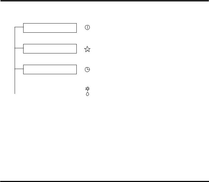
Display Function
Operation Indicator
• Cooling, Soft Dry, Fan, Heating
Sleep timer Indicator
• Sleep Mode
Timer Indicator
• Timer Mode
|
Defrost Indicator or |
|
: Cooling & Heating Model only |
|
|
|
|
|
Hot start Indicator |
OUT |
: only Cooling Model |
|
|||
|
|
||
|
|
DOOR |
|
|
|
|
•Hot-start, Defrost
•Compressor ON
•BUZZER SOUND
• Power Input or Reset |
: One short beep. |
|
• When Operation Stop Button is pressed |
: One long beep. |
|
• When Remote Controller Buttons except for Operation Stop are pressed : Two short beep.
Self-diagnosis Function
CODE NO. |
DIAGNOSIS |
Operation Indicator LED Blinks |
Unit Operation |
|
|
|
|
|
|
|
Indoor room temperature thermistor or |
Once |
Still Operation |
|
pipe temperature thermistor Short/Open |
||||
|
|
|
||
|
|
|
|
|
|
Outdoor pipe thermistor Short/Open |
Twice |
Outdoor Unit Off |
|
|
|
|
|
|
|
Communication failure between indoor and |
5 times |
Stop |
|
outdoor |
||||
|
|
|
||
|
|
|
|
•LED blinks as many times as code No. (0.5 second ON/0.5 second OFF) with 3 seconds interval.
•While the unit is off, no indication displays.
•If more than one code occurs simultaneously, bigger code No. is displayed.
-22 -
 Loading...