


INSTALLATION, OPERATION & MAINTENANCE MANUAL
InverterFlex® Series
Indoor Ductless Mini-Split
Heat Pumps
B-VFH09MA-1
B-VFH12MA-1
B-VFH18MA-1
Heat Controller • 1900 Wellworth Ave. • Jackson, MI 49203 • (517)787-2100 • www.heatcontroller.com

VFH InverterFlex® - Indoor Ductless Mini-Split |
Heat Controller |
TABLE OF CONTENTS
Warnings and Cautions........................................................................................................ |
3 |
Parts Identification................................................................................................................ |
4 |
Operation of Wireless Remote Control............................................................................. |
5-9 |
Special Features of Wireless Remote Control................................................................... |
10 |
Battery Installation and Replacement................................................................................ |
10 |
Manual Operation............................................................................................................... |
11 |
Operation Tips.................................................................................................................... |
12 |
Care and Cleaning............................................................................................................. |
13 |
Troubleshooting............................................................................................................ |
14-16 |
Installation Notices............................................................................................................. |
17 |
Installation of Location and Clearances............................................................................. |
18 |
Indoor Unit Installation.................................................................................................. |
19-20 |
Indoor Wiring...................................................................................................................... |
21 |
Initial Start-up Checks........................................................................................................ |
23 |
Installation of Optional Filter............................................................................................... |
23 |
!Caution
•Contact an authorized service technician for repair or maintenance of this unit
•Contact an authorized installed for installation of this unit.
•Installation work must be performed in accordance with local and national electrical codes and standards by authorized personnel only
2

Heat Controller |
VFH InverterFlex® - Indoor Ductless Mini-Split |
•Read the follow SAFETY PRECAUTIONS carefully before installation.
•Electrical work must be performed by a licensed electrician.
•Incorrect installation due to ignoring the instruction will cause harm or damage. n The seriousness is classified by the following indications.
!WARNING! This symbol indicates the possibility of death or serious injury.
! CAUTION! This symbol indicates the possibility of injury or damage to property.
The items to be followed are classified by the symbols:
This symbol denotes item that is PROHIBITED from doing.
!WARNING!
1)Do not install without an authorized servicer/installer.
2)Install according to this installation instruction. If installation is defective, it can cause water leakage, or electric shock/fire.
3)Use the supplied accessories and specified parts for installation.
4)Install the indoor unit on a wall strong enough to hold the unit’s weight.
5)For electrical work, follow local and national electric codes and these installation instructions. An independent circuit and single outlet must be used. If electrical circuit capacity is not enough or defects are found in electrical work, it may cause electrical shock or fire.
6)Use the specified cable and connect tightly. Clamp the cable so that no external force will stress the connections. Loose wiring may overheat at the connection points and create a possible fire hazard.
7)Wiring routing must be properly arranged so that control board cover is fixed properly. If control board cover is not fixed perfectly, it will cause overheating at connection point of terminal, fire or electrical shock.
8)When charging the unit, take care not to let air/substances other than the specified refrigerant go into refrigeration circuit. Otherwise it will cause lower capacity, abnormal high pressure
in the refrigeration circuit, explosion and injury.
!CAUTION!
1)This equipment must be grounded it may cause electrical shock if grounding work doesn’t comply with local/national electric codes.
2)Do not install the unit in place where leakage of flammable gas may occur. If gas
leaks and accumulates near the unit, it may cause fire.
3)Condensate must properly drain away from the unit as mentioned in installation instructions. If not done correctly, water may enter the room and damage personal belongings.
3
VFH InverterFlex® - Indoor Ductless Mini-Split |
Heat Controller |
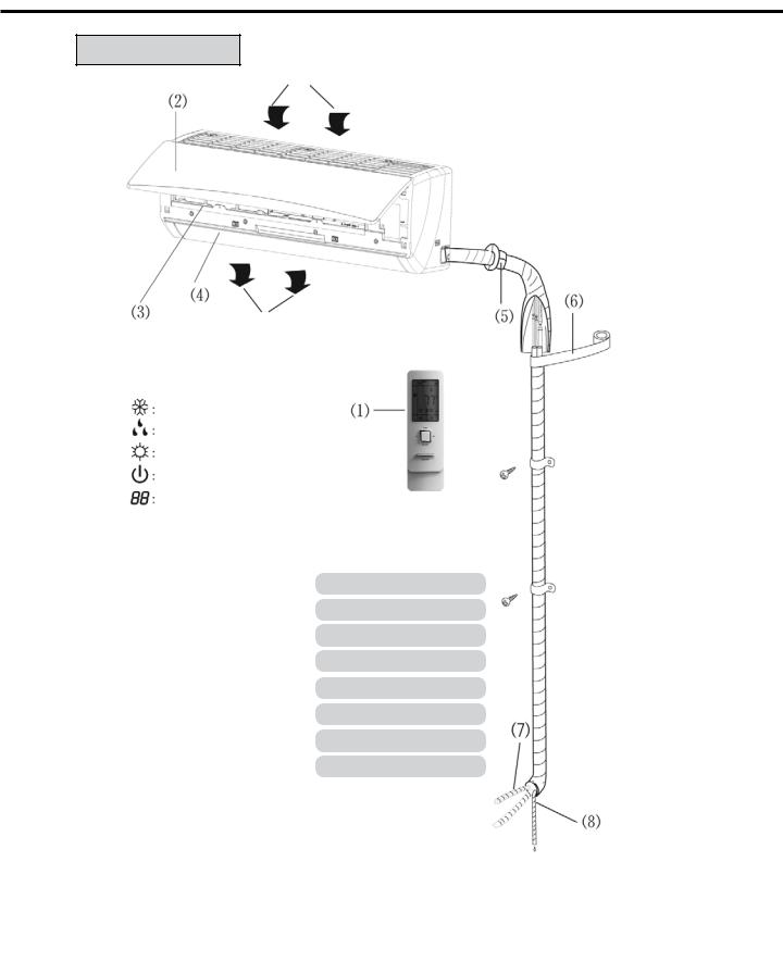
Parts Identification
Indoor Unit
Air Inlet
Air Outlet
The icons displayed:
Cool
Dry
Heat
Power
Set temp.
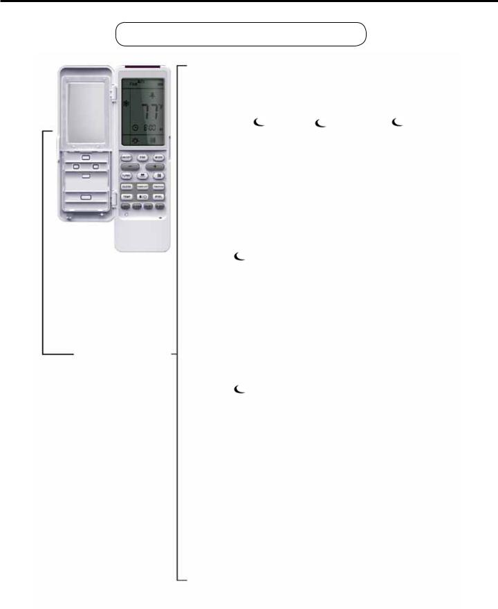
(1)Remote controller
(2)Front panel
(3)Filter
(4)Horizontal louver
(5)Wall pipe bushing
(6)Binding tape
(7)Connection pipes
(8)Condensate drain hose
4
Heat Controller |
VFH InverterFlex® - Indoor Ductless Mini-Split |
Operation of wireless remote control
Features and functions of wireless remote control
Note: Be sure that there are no obstructions between the unit’s receiver and remote control. Be careful not to drop the remote control; Don’t let any liquid get inside the remote control, don’t put the remote control directly in sunlight or any other place where it is very hot.
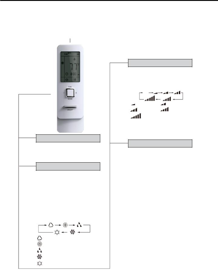
Signal transmitter
Remote controller
NOTE: When operating buttons on the cover please make sure the cover is closed completely on the remote.
ON/OFF ON/OFF button
• Press this button, the unit will turn on, press it once more, the unit will turn off. Sleep function cancels while unit is off.
MODE
MODE button
• Press this button, Auto, Cool, Dry, Fan, Heat mode can be selected sequentially. When unit powers on, Auto mode is the default mode. In Auto mode, the temperature is not shown on the display. The unit will operate in heating or cooling modes automatically based on the room temperature. Under Heat mode the initial set point is 28°C (82°F);
in other modes, the initial set point is 25°C (77°F).
AUTO
COOL
DRY
FAN
HEAT
FAN
FAN button
• Press this button, Auto, Low, Medium-low, Medium, Medium-high, High speed can be sequentially selected. Auto mode is the default mode. In dry mode, the only available fan speed is low.
AUTO
Low fan |
Medium-low fan |
Medium fan |
Medium-high fan |
High fan |
|
TEMP
TEMP button
• Press this button, the following temperatures can be set sequentially: the set temperature, indoor ambient temperature and outdoor ambient temperature. When the indoor unit first powers on, it will display the set temperature and this icon  . If the button is pressed again, this icon
 and the
indoor ambient temperature is shown. Pressing the button a third time will display this icon and the outdoor ambient temperature. 3 seconds later the display will return to the set temperature or unless there is another signal.
NOTE: Outdoor ambient temperature display range is 0~60°C (32~99°F). However, if the outdoor ambient temperature is below 0°C, it still will display 0°C (32°F). The display can’t show temps below 0°C (32°F).
VFH InverterFlex® - Indoor Ductless Mini-Split |
Heat Controller |
Operation of wireless remote control
Features and functions of wireless remote control
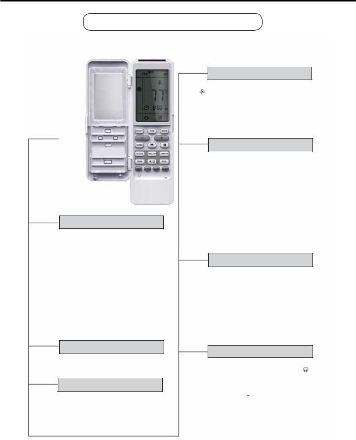
Remote controller
CLOCK CLOCK button
• To set the time, press the clock button until the clock symbol blinks. While blinking, the time can be adjusted by pressing the (+) or (-) buttons within 5 seconds. Once the time is set, press the clock button again to confirm, the clock symbol  will no longer blink. The first time the unit is powered on the time will display 12:00 as the default.
X-FAN
X-FAN button
• By pressing X-FAN button in COOL or DRY mode, the icon is displayed and the indoor fan will operate for 2 minutes in order to dry the indoor unit after powering off the unit. X-FAN OFF is the default setting. The X-FAN feature is not available in AUTO, FAN or HEAT mode. The X-FAN mode is used to dry the unit out when it won’t be used for a long time. This helps prevent mold and mildew from forming inside the unit.
+
+ button
• Using this button, the temperature can be increased. The temperature can be set to 61-86°F (16-30°C). The temperature
adjustment can not be made in Auto mode.
-
- button
• Using this button the temperature can be decreased. The temperature can be set to 61-86°F (16-30°C). The temperature adjustment can not be made in Auto mode.
LIGHT
LIGHT button
•When powered on the light is defaulted on. Press the light button to turn on/off the light.
TURBO TURBO button
•Under Cool or Heat mode, the turbo button can turn on or turn off the Turbo function. After the Turbo function turned on, the Turbo symbol will display. The Turbo mode will be automatically cancelled if the mode or fan speed is changed. The Turbo mode can be used to quickly heat or cool the room.
QUIET
QUIET button
When quiet mode is used, the fan operates at a low speed. Pressing the Quiet button activates the mode and the icon “ “ is displayed. To cancel Quiet mode, press the button again.
•When Quiet mode is selected during the cooling mode, the fan speed operates at Medium-high speed for 10 minutes or until the room temperature is < 82°F (28C), after that the fan speed decreases to Medium-low.
•In heating mode, the indoor fan operates at Medium fan speed.
•During Auto mode, when Quiet mode is enabled, the Quiet icon
“  “ along with the “AUTO” icon is displayed. The fan will operate as noted above, depending on the mode the unit selects based on the room temperature (COOL, HEAT, or FAN ONLY).
6
Heat Controller |
VFH InverterFlex® - Indoor Ductless Mini-Split |
Operation of wireless remote control
Features and functions of wireless remote control
TIMER OFF TIMER OFF button
• Press the Timer off button to create the timer off program. The Timer off icon will blink, indicating it is in programming mode. The set up process is the same as the timer on process - see Timer On for instructions. The timer off program allows you to determine when the unit should turn off based on how much time has transpired.
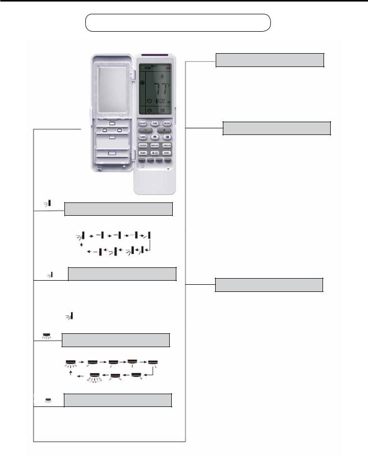
Remote controller
SWING UP AND DOWN button
•Press this button to set swing angle of the louver, which cycles through the options below.
•Adjust the swing
of the louver to direct the air
flow to the most OFF comfortable
position.
AUTO LOUVER SWING button
•Press swing, + and - buttons continuously for more than 2s, the louver will swing back and forth when you release the button, the louver will stop swinging and the present position of the louver will be kept.
• This icon indicates that the louver swings back and forth.
SWING LEFT AND RIGHT button
• Press this button to set left & right swing angle cycling as shown below.
OFF
• Adjust the swing of the louver to direct the air flow to the most comfortable position.
AUTO LOUVER SWING LEFT-RIGHT button
•Press swing left and right buttons continuously more than 2s the lower will swing back and forth from the left to the right. When you release the buttons the louver will stop swinging and the present position of the louver will be kept.
TIMER ON TIMER ON button
• The Timer feature is a program that can be used to turn the unit on/off after a certain amount of time has transpired. To set the Timer on, press the Timer on button. The “ON” icon will blink indicating that the program can be set. Press the (+) or (-) buttons to adjust the time duration in minutes. After the time duration is set, press the Timer on button again to begin the Timer on operation. To cancel the Timer on operation, press the Timer on button again.
NOTE: Be sure the clock is set to the actual time before setting the timer. See clock instructions to set the clock time.
I FEEL |
I FEEL button |
|
• Due to temperature stratification in the room, it is more comfortable if the unit senses the temperature at the level the remote sits, rather that at the indoor unit, which is up high on the wall. To select the sensing at the remote control room temperature rather than at the unit, press the I-FEEL button. The I-FEEL icon will be displayed and the temperature signal will be sent from the remote to the unit every 10 minutes as long as the remote controller is in range of the indoor unit. To cancel, press the I-FEEL button again.
7
VFH InverterFlex® - Indoor Ductless Mini-Split |
Heat Controller |
Operation of wireless remote control
Features and functions of wireless remote control
Sleep Button:
The sleep program allows for the most comfortable conditions while you sleep, as body temperatures change. To activate the sleep mode, press the sleep mode button. There are (3) different programmed settings to choose from Sleep 1 ( 1), Sleep 2 ( 2), and Sleep 3 ( 3) described below. To cancel the Sleep mode, press the Sleep mode button and cycle through options 1, 2, and 3, until the Sleep icon disappears from the display.
NOTE: The Sleep function can not be enabled when the unit is in Fan or Auto mode. Sleep 1 can only be selected when the unit is in Cool or Dry mode. When Sleep mode is enabled, Quiet mode is also automatically enabled
in conjunction. However, Quiet mode can be turned off manually.
|
|
Sleep 1 ( 1): |
|
|
|
When Sleep 1 is activated while the unit is in Cool or Dry |
|
|
|
mode, the unit’s set temperature will increase 1-2 degrees |
|
|
|
during the first hour, then after 2 hours it will decrease |
|
|
|
by 3-4 degrees more and then continue to run at this |
|
|
|
temp. When Sleep mode is activated while the unit is in |
|
|
|
Heat mode, the unit will operate by decreasing the set |
|
|
|
temperature by 1-2 degrees the first hour and then by |
|
SLEEP |
|
3-4° degrees the next 2 hours. Then the unit will continue |
|
SLEEP button |
|||
to run at this temperature. |
Sleep 2 ( 2):
Sleep 2 operates differently than Sleep 1, as it takes into account the set temperature.
Cool Mode:
•When the initial set temperature is between 61°F-74°F (16°C-23°C), the temperature will increase 1-2 degrees every hour until it reaches a 5-6 degree difference. It will operate at this setting for (7) hours. After 7 hours, the temperature will decrease 1-2 degrees and continue to operate under this condition.
•When the initial set temperature is between 75°F-81°F (24°C-27°C), the temperature will increase 1-2 degrees every hour until a 3-4 degree difference is achieved.
This will be maintained for (7) hours, after which another 1-2 degree decrease will take place. Then the unit will continue to operate under this condition.
8
 Loading...