

Page 1
Wall Mounted
Mini-Split System
Inverter Single-Zone
Air Conditioning
Service Manual
AS-Q1835JZ0 [VMC18SB-1]
AS-Q2435JZ0 [VMC24SB-1]
Before servicing the unit, read the
“safety precautions” in this manual.
Only for authorized service personnel.
HEAT CONTROLLER, INC.
Page 2
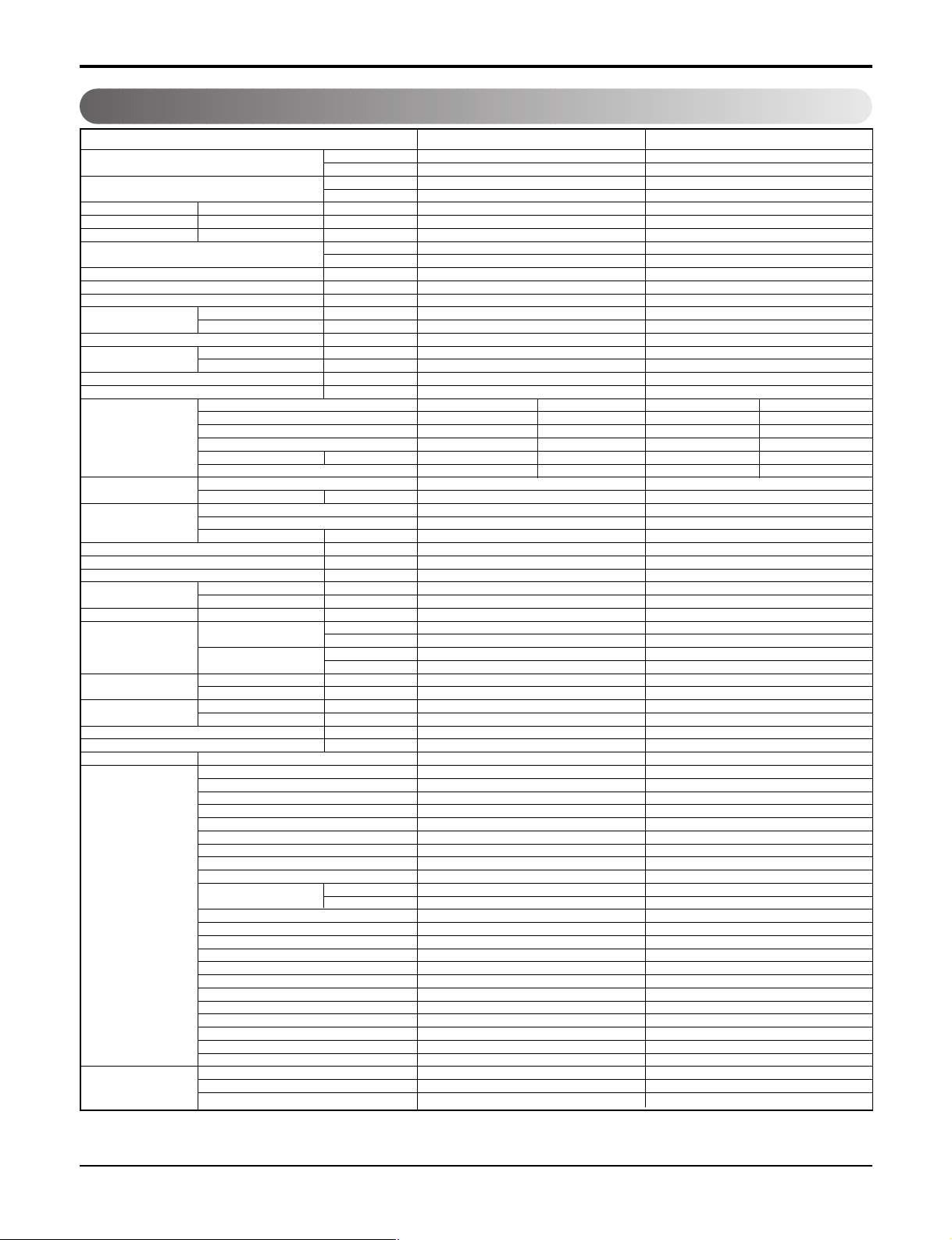
1. Specification
Models
Cooling Capacity kW
(Min~Rating~Max) Btu/h
Heating Capacity kW
(Min~Rating~Max) Btu/h
Power Input Cooling/Heating W
Running Current Cooling/Heating A
Starting Current Cooling/Heating A
EER W/W
COP W/W
Power Supply Ø / V / Hz
Power Factor %
Air Flow Rate Indoor,Max mm3/min(cfm)
Moisture Removal l/h
Sound Level Indoor,H/M/L dB(A)+3
Refrigerant & Charge(at 7.5m) g(oz)
Additional Refrigerant Charge g/m(oz/ft)
Compressor Type
Fan(Indoor) Type
Fan(outdoor) Type
Circuit Breaker* A
Power Supply Cable NEC
Power and Transmission Cable NEC
Piping Liquid Side mm(in)
Connections Gas Side mm(in)
Drain Hose O.D , I.D mm(in)
Dimension Indoor(W*H*D) mm
Net Weight Indoor kg(lbs)
Operation Range Cooling(Outdoor) ˚C
Max. Piping Length m(ft)
Max. Elevation Difference m(ft)
Tool Code(Chassis) Indoor + Outdoor
Functions Temperature Control
Network Functions Dry Contact
Outdoor,Max mm3/min(cfm)
Outdoor,Max dB(A)+3
Model
Motor Type
Oil Type
Oil Charge cc
O.L.P Name
Motor Output W
Motor Type
Motor Output W
Outdoor(W*H*D) mm
Outdoor kg(lbs)
Heating(Outdoor) ˚C
Plasma Filter
Prefilter(washable/anti-fungus)
Auto Clean
CHAOS Wind(Auto Wind)
Steps, Fan/Cool/Heat
Airflow Direction Control(up&down)
Airflow Direction Control(left&right)
Remocon Type
Setting Temperature Cooling
Range Heating
Auto Operation (Micom Control)
Auto Changeover (Micom Control)
Self Diagnosis
Timer
Sleep Operation
Soft Dry Operation
Restart Delay(minute)
Deice Control(Defrost)
Hot Start
Jet Cool / Heat
Low Ambient Operation
Special Function
Network Solution(LGAP)
PI485
Note:
O
: Applied, - : No relation
*
For circuit breaker rating, please conform to local standards wherever necessary.
Btu/h.W
inch
inch
AS-Q1835JZ0 [VMC18SB-1] AS-Q2435JZ0 [VMC24SB-1]
1.76~5.28~5.80 3.87~7.03~7.74
6,005~18,000~19,790 13,200~24,000~26,400
1/208-230/60 1/208-230/60
R410A, 1,200(42) R410A, 1,800(63)
Rotary Rotary
5CS130XCA03 5KD240XCA21
BLDC BLDC
RB68A FV50S
360 900
-Cross Flow Fan Cross Flow Fan
21.5,16(0.85,0.63) 21.5,16(0.85,0.63)
1,090*300*178 1,090*300*178
42.9*11.8*7.0 42.9*11.8*7.0
870*655*320 870*800*320
34.3*25.8*12.6 34.3*34.6*12.6
-10 ~ 46 (14.0114.8)(Low Ambient) -10 ~ 46 (14.0~114.8)(Low Ambient)
Wireless LCD Wireless LCD
18 ~ 30 (64~86) 18 ~ 30 (64~86)
❈
Some of functions are slightly different depending upon models.
❈
The specification may be subject to change without prior notice for purpose of improvement.
❈
Capacity : based on 203V.
--
--
1640/- 2450/-
7.3/- 11.0/-
7.3/- 11.0/-
3.22 2.87
11.0 9.8
--
98 97
18.5(650) 20.3(717)
42(1,483) 58(2,048)
2.1 2.7
40/38/34 45/40/37
53 54
20(0.22) 30(0.32)
20 24
Propeller Propeller
BLDC AC Induction
85.3 76.5
20 25
14 12
18 18
6.35(1/4) 9.52(3/8)
12.7(1/2) 15.88(5/8)
13.0(28.7) 13.0(28.7)
48(105.8) 66(145.5)
--
15(49) 30(98)
7(23) 15(49)
S8 + UE S8 + UE1
Thermistor Thermistor
-OO
OO
OO
-/4/4 -/4/4
Auto Auto
Auto Auto
--
--
-OO
24h On/Off 24h On/Off
OO
OO
22
--
--
O / - O / -
OO
--
--
--
--
Copyright ©2008 LG Electronics. Inc. All right reserved.
Only for training and service purposes
- 2 -
LGE Internal Use Only
Page 3
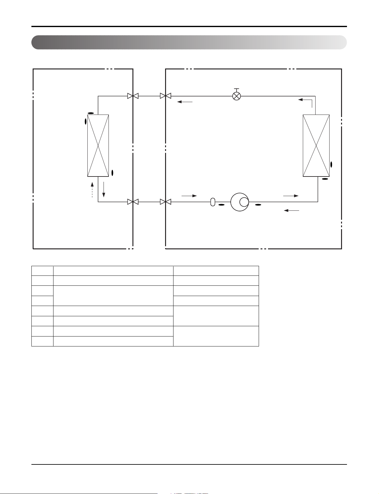
2. Piping Diagrams
Indoor Unit Outdoor Unit
Liquid Side
EEV
Th1
Th2
2-Way Valve
Heat
Exchanger
(Evaporator)
Th3
Gas Side
3-Way Valve
Accumulator
Compressor
LOC. Description PCB Connector
Th1 Thermistor for indoor air temperature CN_TH1(INDOOR)
Th2
CN_TH2(INDOOR)
Thermistor for evaporating temperature
Th3 CN_TH3(INDOOR)
Th4 Thermistor for outdoor air temperature
CN_TH2(OUTDOOR)
Th5 Thermistor for condensing temperature
Th6 Thermistor for discharge pipe temperature
CN_TH3(OUTDOOR)
Th7 Thermistor for suction pipe temperature
Heat
Exchanger
(Condenser)
Th4
Th5
Th6Th7
Refrigerant Flow
Copyright ©2008 LG Electronics. Inc. All right reserved.
Only for training and service purposes
- 3 -
LGE Internal Use Only
Page 4

3. Wiring Diagrams
Indoor Unit
CN_MOTOR1
CN_HUB/UV
CN_L/R(BL)CN_L/R(BL)
CN_DISP2(BL)
CN_12V
CN_DISP(WH)
CN_TH1
CN_TH2
Copyright ©2008 LG Electronics. Inc. All right reserved.
Only for training and service purposes
- 4 -
LGE Internal Use Only
Page 5

Outdoor Unit
CN_COIL2
CN_COIL1
CN_FAN(A)CN_4WAY
CN_TH3
CN_TH1
CN_TH2
CN_LEV1
Copyright ©2008 LG Electronics. Inc. All right reserved.
Only for training and service purposes
- 5 -
LGE Internal Use Only
Page 6

4. Exploded View
152301
342800
263230
359011
131410
135316
135314
135311
268711A
146811
346810
135516
35211B
352150
354210
149304
249951
268711B
267110
147581
733010
Indoor Air, Evaporator
Thermistor
Indoor Unit
Note) * Please ensure GCSC since the replacement parts may be changed depending upon the buyer's request.
Please check the correct parts in View RPL(Replacement Part List) on GCSC.
(GCSC Website http://biz.Lgservice.com,)
Copyright ©2008 LG Electronics. Inc. All right reserved.
Only for training and service purposes
- 6 -
LGE Internal Use Only
Page 7

Outdoor Unit 18k
554031
263230B
435512
437212
435511
268711F
550140
552203A
552203B
447910
567480E
Discharge
Suction
S-pipe, D-pipe
Thermistor
649950
W0CZZ
437211
559010
546810
435301
349480
349600
661400
552113
437210
554160
261704
430960A
Outdoor Air, Condenser
Thermistor
EEV Coil
Note) * Please ensure GCSC since the replacement parts may be changed depending upon the buyer's request.
Please check the correct parts in View RPL(Replacement Part List) on GCSC.
(GCSC Website http://biz.Lgservice.com,)
Copyright ©2008 LG Electronics. Inc. All right reserved.
Only for training and service purposes
- 7 -
LGE Internal Use Only
Page 8

Outdoor Unit 24k
435300
137213B
137213A
435512
554031
552202
552116
661400
263230D
435511
263230E
554160
550140
649950
261704
W0CZZ
668711F
552113
559010
437211
435301
546810
549610
447910
552203A
552203B
263230E
430960A
EEV Coil
Outdoor Air, CondenserOutdoor Air, Condenser
Thermistor Thermistor
Outdoor Air, Condenser
Thermistor
S-pipe, D-pipe
Thermistor
S-pipe, D-pipe
Thermistor
Note) * Please ensure GCSC since the replacement parts may be changed depending upon the buyer's request.
Please check the correct parts in View RPL(Replacement Part List) on GCSC.
(GCSC Website http://biz.Lgservice.com,)
Copyright ©2008 LG Electronics. Inc. All right reserved.
Only for training and service purposes
- 8 -
LGE Internal Use Only
Page 9

Specifications and performance data subject to change without notice.
HEAT CONTROLLER, INC.
1900 WELLWORTH AVENUE • JACKSON, MICHIGAN 49203
THE QUALITY LEADER IN CONDITIONING AIR
P/No.:MFL42286413
 Loading...