

Page 1
INSTALLATION, OPERATION
& MAINTENANCE MANUAL
InverterFlex® Series
Outdoor Ductless Mini-Split
Heat Pumps
A-VFH18DA-1
A-VFH24TA-1
A-VFH30QA-1
A-VFH36QA-1
A-VFH42PA-1
Heat Controller • 1900 Wellworth Ave. • Jackson, MI 49203 • (517)787-2100 • www.heatcontroller.com
Page 2

VFH InverterFlex® - Outdoor Ductless Mini-Split Heat Controller
TABLE OF CONTENTS
Safety Precautions
Warnings and Cautions............................................. 3
Introduction
Model Nomenclature.................................................4
System Application....................................................5
Installation Instructions
Installation Location Selection............................... 6-7
Outdoor unit installation..........................................8-9
Condensate Drain......................................................9
Refrigerant Line Installation
Refrigerant line set installation............................ 10-15
Leak test, evaluation and release of refrigerant....... 16
Electrical Work
Electrical Precautions.............................................16
Unit wiring........................................................... 17-21
Initial Start Up and Checks
Field charging and Final Inspection ................... 21-23
!
Caution
• Contact an authorized service technician for repair or maintenance of
this unit
• Contact an authorized installed for installation of this unit.
• Installation work must be performed in accordance with local and
national electrical codes and standards by authorized personnel only
2
Page 3
Heat Controller VFH InverterFlex® - Outdoor Ductless Mini-Split
• Read the follow SAFETY PRECAUTIONS carefully before installation.
• Electrical work must be performed by a licensed electrician. Be sure to use the correct rating of the power
cord and main circuit for the model to be installed.
• Incorrect installation due to ignoring the instruction will cause harm or damage.
n The seriousness is classied by the following indications.
WARNING!
!
CAUTION!
!
The items to be followed are classied by the symbols:
This symbol indicates the possibility of death or serious injury.
This symbol indicates the possibility of injury or damage to property.
This symbol denotes procedure that is PROHIBITED.
WARNING!
!
1) Do not install without an authorized servicer/installer.
2) Install according to this installation instruction. If installation is defective, it can cause water leakage or
electrical shock/re.
3) Use the supplied accessories and specied parts for installation.
4) Install the outdoor unit on a raised concrete pad or blocks to provide a solid, level foundation. In a
location with high winds, anchor the unit and provide an air bafe. In snowy areas (for heat pump
models), install the outdoor unit on a raised platform higher than drifting snow. Provide snow vents, and
awning over the unit.
5) For electrical work, follow local and national electric codes and these installation instructions. An
independent must be used. If defects in the electrical work, will cause electrical shock or re.
6) Use the specied cable and connect tightly. Clamp the cable so that no external force will stress the
connections. Loose wiring may overheat at the connection points and create a possible re hazard.
7) Wiring routing must be properly arranged so that control board cover is xed properly. If control board
cover is not xed perfectly, it will cause overheating at connection point of terminal, re or electrical shock.
8) When charging the unit, take care not to let air/substances other than the specied refrigerant
go into refrigeration circuit. Otherwise, it will cause lower capacity, abnormal high pressure in the
refrigeration circuit, explosion and injury.
9) Do not modify the length of the power supply cord or use an extension cord, and do not share
the single outlet with other electrical appliances. Otherwise, it will cause re or electrical shock.
CAUTION!
!
1) This equipment must be grounded. It may cause electrical shock if grounding doesn’t comply with local/
national electric codes.
2) Do not install the unit in a place where leakage of ammable gas may occur. If gas leaks and
accumulates near the unit, it may cause re.
3) Provide proper condensate drainage per the installation instructions. If not done properly, condensate
can destroy personal property and freeze up in improperly on the unit.
3
Page 4
VFH InverterFlex® - Outdoor Ductless Mini-Split Heat Controller
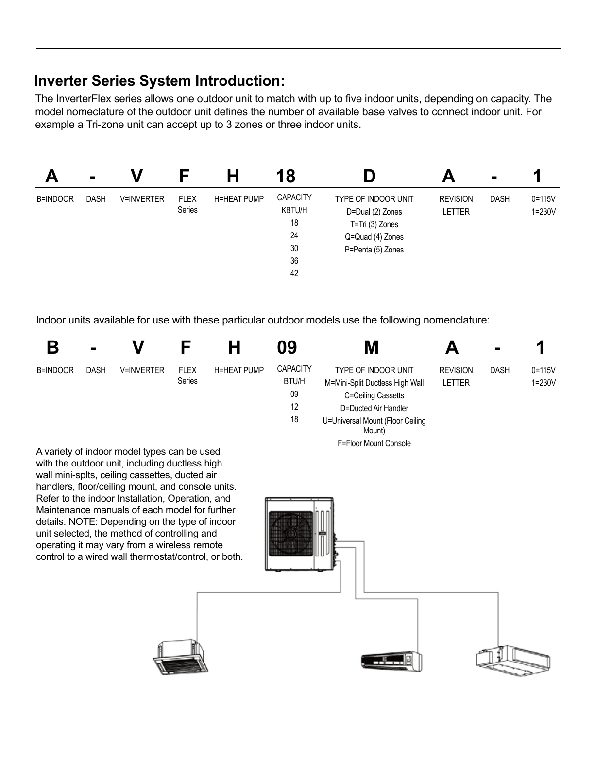
Inverter Series System Introduction:
The InverterFlex series allows one outdoor unit to match with up to ve indoor units, depending on capacity. The
model nomeclature of the outdoor unit denes the number of available base valves to connect indoor unit. For
example a Tri-zone unit can accept up to 3 zones or three indoor units.
Indoor units available for use with these particular outdoor models use the following nomenclature:
A variety of indoor model types can be used
with the outdoor unit, including ductless high
wall mini-splts, ceiling cassettes, ducted air
handlers, oor/ceiling mount, and console units.
Refer to the indoor Installation, Operation, and
Maintenance manuals of each model for further
details. NOTE: Depending on the type of indoor
unit selected, the method of controlling and
operating it may vary from a wireless remote
control to a wired wall thermostat/control, or both.
A - V F H 18 D A - 1
B=INDOOR
H=HEAT PUMP
FLEX
Series
V=INVERTER
DASH
CAPACITY
KBTU/H
18
24
30
36
42
0=115V
1=230V
DASH
REVISION
LETTER
TYPE OF INDOOR UNIT
D=Dual (2) Zones
T=Tri (3) Zones
Q=Quad (4) Zones
P=Penta (5) Zones
B - V F H 09 M A - 1
B=INDOOR
H=HEAT PUMP
FLEX
Series
V=INVERTER
DASH
CAPACITY
BTU/H
09
12
18
0=115V
1=230V
DASH
REVISION
LETTER
TYPE OF INDOOR UNIT
M=Mini-Split Ductless High Wall
C=Ceiling Cassetts
D=Ducted Air Handler
U=Universal Mount (Floor Ceiling
Mount)
F=Floor Mount Console
Outdoor Nomenclature A-VFH18DA-1
Indoor Nomenclature B-VFH09MA-1
EXAMPLE OF TRI-ZONE SYSTEM
Outdoor Unit
Cassette Type
Indoor Unit
Wall Mounted
Indoor Unit
Duct Type Indoor
Unit (Rectangular
air outlet)
4
Page 5
Heat Controller VFH InverterFlex® - Outdoor Ductless Mini-Split
Inverter Series System Introduction:
System Selection:
The total capacity of ALL the indoor units can not
exceed 150% of the capacity of the outdoor unit.
However, we recommend sizing the indoor unit’s
total capacity to be less than or equal to 100% of
the outdoor unit’s capacity. If sized beyond 100% of
the outdoor unit’s capacity, when all the indoor units
receive a call for cooling/heating, the entire system
will still only be able to achieve the rated capacity. of
the outdoor unit The inverter compressor can run at
a higher frequency but may not provide full capacity
to all indoor units. Sizing above 100% is usually done
because one or more indoor units may not be in use
the majority of the time.
Additionally, the total capacity of all indoor units cannot
be less than 50% of the outdoor unit’s capacity.
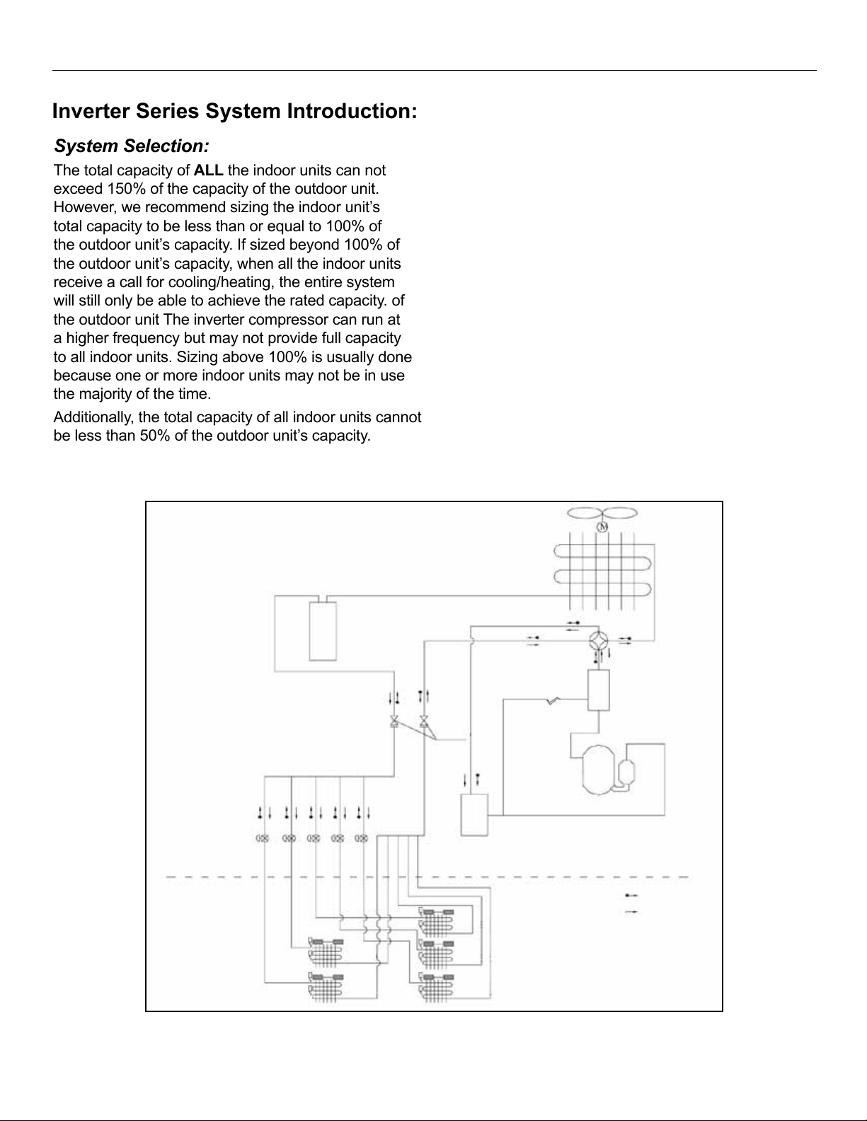
System Application:
This system is not designed to be a sole source of
heat for a home/building. While the units can operate
in low ambient conditions, they cannot provide the full
rated capacity for heat at low outdoor temperatures. An
additional heat source may be required in areas such
as the northern USA and Canada during the winter.
This system must be run in modes that do not conict.
For example, one indoor unit cannot be run in cool
mode and another indoor unit in heat mode. All indoor
units modes must be harmonized for the system to
properly operate. The fan mode can run in conjunction
with any other mode, while the cooling mode can be
run in conjunction with the dehumidication mode.
However all other modes must match among the
indoor units.
Liquid Receiver
Outdoor Unit
NOTE: The number of indoor units may vary depending on the capacity of the outdoor unit. This is an
example of a ve (5) zone system.
Electronic
Expansion Valve
Indoor Unit
Heat Exchanger
Heat Exchanger
System Schematic
Heat Exchanger
Stop
Valve
Heat Exchanger
Heat Exchanger
Heat Exchanger
5
Capillary
Compressor
Gas/Liquid Separator
Four Way Valve
Oil Separator
Heating
Cooling
Page 6
VFH InverterFlex® - Outdoor Ductless Mini-Split Heat Controller
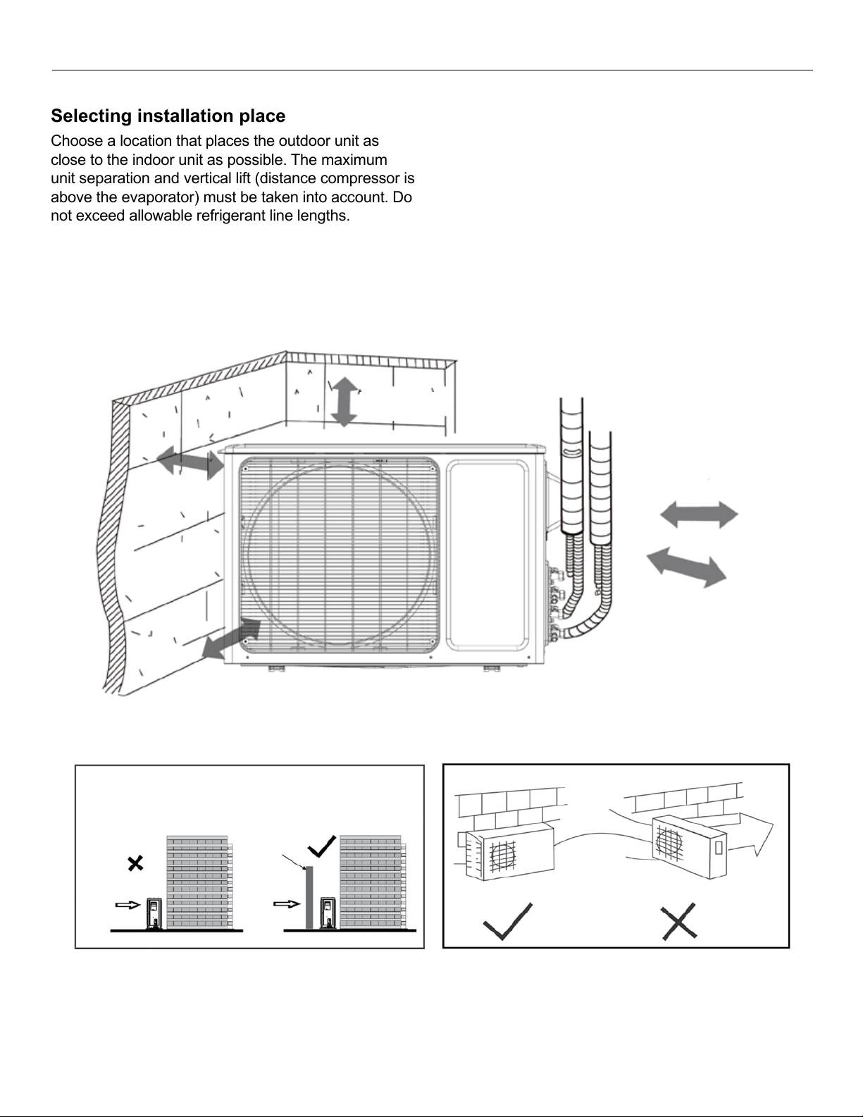
Selecting installation place
Choose a location that places the outdoor unit as
close to the indoor unit as possible. The maximum
unit separation and vertical lift (distance compressor is
above the evaporator) must be taken into account. Do
not exceed allowable refrigerant line lengths.
Outdoor unit
• Unit must be installed in a location that does not
obstruct the airow and ensures clearance are
maintained (Fig. 1)
• If installation location allows the unit to be exposed
to strong winds (such as coastal applications),
ensure that the unit has a wind barrier. This will
assist with preventing strong gusts of wind from
entering the unit’s cabinet and interfering with the
Fig. 1
fan operation. (Fig. 2 and Fig. 3)
Fig. 2
Min. 1.5ft.
(500mm)
Min. 6.5ft. (2000mm)
(Air outlet side)
CorrectIncorrect
Min. 3.5ft.
(1000mm)
Min. 1.5ft.
(500mm)
(Air inlet side)
Min. 1.5ft. (500mm)
Space to the wall
Fig. 3
Correct
Incorrect
6
Page 7
Heat Controller VFH InverterFlex® - Outdoor Ductless Mini-Split
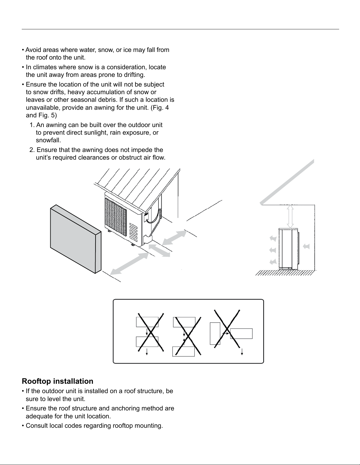
• Avoid areas where water, snow, or ice may fall from
the roof onto the unit.
• In climates where snow is a consideration, locate
the unit away from areas prone to drifting.
• Ensure the location of the unit will not be subject
to snow drifts, heavy accumulation of snow or
leaves or other seasonal debris. If such a location is
unavailable, provide an awning for the unit. (Fig. 4
and Fig. 5)
1. An awning can be built over the outdoor unit
to prevent direct sunlight, rain exposure, or
snowfall.
2. Ensure that the awning does not impede the
unit’s required clearances or obstruct air ow.
Rooftop installation
• If the outdoor unit is installed on a roof structure, be
sure to level the unit.
• Ensure the roof structure and anchoring method are
adequate for the unit location.
• Consult local codes regarding rooftop mounting.
3. The awning should be at least 2 ft. (0.6m) away
from the top of the unit’s housing.
• Ensure free ow of air into and out of the unit. All air
inlet/outlets should be free of obstructions such as
walls and shrubs. Minimum clearances should be
maintained. (Fig. 1)
• During heating and defrost modes (heat pump
models only), the condensate should be properly
drained away from the unit. • Do not locate two or
more units in any way that will block discharge air
from one unit to another. Be certain that hot air from
one unit will not blow into a nearby unit to prevent
recirculation or discharge air. (Fig. 6)
Fig. 4
Obstacles
Fence or
Min. 6.5ft (2000mm)
Fig. 6
Min. 1.5ft (500mm)
Min. 1.5ft (500mm)
Fig. 5
Min. 3.5ft (1000mm)
(Service space)
• If the outdoor unit is installed on roof structures
or external walls, excessive noise and vibration
may result, and may also be considered a nonserviceable installation.
• Oil traps must be made in the refrigerant line set
(every 10 ft.) when the outdoor unit is located above
the indoor unit.
7
Page 8
VFH InverterFlex® - Outdoor Ductless Mini-Split Heat Controller
Outdoor Unit Installation
• In a snowy area, slab should be higher than drifting
• Install the outdoor unit on a rigid base (such a
concrete slab) to prevent increasing noise level and
vibration.
• Use a raised concrete pad or concrete blocks to
provide a solid, level surface. Securely anchor the
unit down with bolts.
snow.
• See outdoor installation location information
on pages 6 and 7 for more details and required
clearances.
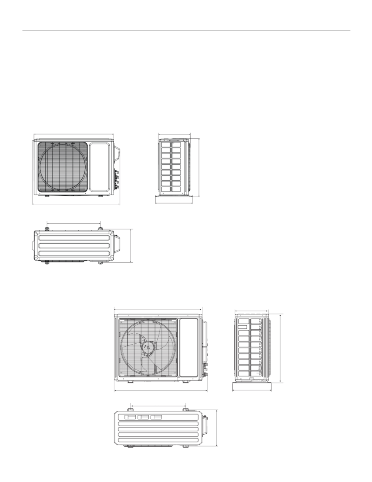
Anchoring outdoor unit
FIG. 7 18KBTU/H
32.09 in. (815mm)
35.39 in. (899mm)
21.65 in. (550mm)
15.5in. (343mm)
12.44 in. (316mm)
14.88in. (378mm)
Anchor the outdoor unit to the concrete
slab with lag bolts or similar size, may
vary by model.
NOTE: Lag bolts are eld provided and do
not come with the unit.
Refer to unit’s mounting footprint for
mounting hole locations (Fig. 7 - 10)
23.46 in. (596mm)
FIG. 8 24KBTU/H, 30KBTU/H
35.12 in. (892mm)
37.24 in. (946mm)
22.05 in. (560mm)
8
13.43 in. (341mm)
27.56in. (700mm)
15.59in. (396mm)
14.5in. (368mm)
Page 9
Heat Controller VFH InverterFlex® - Outdoor Ductless Mini-Split
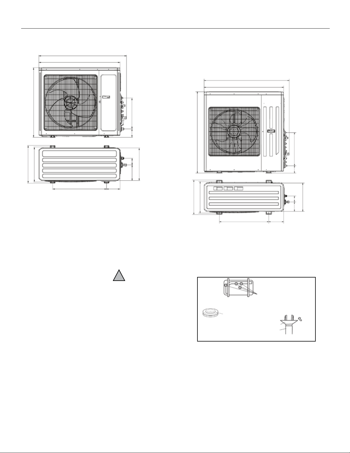
FIG. 9 36KBTU/H
39.13 in. (994mm)
36.22 in. (920mm)
FIG. 10 42KBTU/H
42.8 in. (1087mm)
40 in. (1015mm)
31.06 in. (789mm)
15.55 in. (395mm)
16.81 in. (427mm)
24.62 in. (610mm)
3.78 in. (96mm)
3.78 in.
(96mm)
3.0 in.
(76mm)
6.97 in.
(177mm)
14.57 in. (370mm)
9.02 in. (153mm)
Condensate Drainage
• For heat pump models only.
• Condensate and defrosted water created by the
unit operating in heat mode should be routed
and drained away from the unit.
• Parts needed for condensate drainage are not
factory supplied; they are commercially available.
• Fit the rubber washer onto the drain connector, then
!
43.43 in. (1103mm)
17.32 in. (440mm)
15.79 in. (401mm)
24.84 in. (631mm)
Fig. 11
Bottom frame
Drain plug
Drain connector
Hose (5/8” (16mm) I.D.
17.72 in. (450mm)
3.9 in.
(99mm)
3.0 in.
(76mm)
4.76 in.
(121mm)
14.25 in. (362mm)
7.52 in. (191mm)
Drain-water hole
insert the drain connector into the hole on the base
pan of the outdoor unit. Secure into place. (Fig. 11)
• Connect a locally purchased drain hose. Install
hose to the hose barb end of the drain connector.
• Route the hose to drain location away from
the unit.
• Repeat for each hole on the base of the unit, as
needed.
9
Page 10

VFH InverterFlex® - Outdoor Ductless Mini-Split Heat Controller
Refrigerant Line Set Installation
Refrigerant Line Set Installation
1. Purchase line sets through a Heat Controller
distributor with consideration of the minimum
and maximum line lengths. (Page 11)
2. Both liquid and suction lines to be insulated.
3. Connections are made via are nuts.
4. The number of bends and length of refrigerant
lines determine the pressure drop which affects
capacity and efciency of the system, as well
as oil return. Minimize the length and number of
bends when possible during installation.
5. Minimum line set length must be maintained,
even if the installation does not require it. Extra
length that is unnecessary can be coiled up
near the outdoor unit (Do not to block air inlets/
outlets).
6. Choose a location that places the outdoor
unit as close to the indoor unit as possible to
minimize line set lengths.
7. Use only clean, refrigerant grade tubing suitable
for R-410A.
8. Avoid installing refrigerant lines on wet/rainy
days.
9. Always keep tube ends sealed until the nal
connections are to be made.
10. If line sets are being made at the time of
installation, rather than being purchased, be sure
to:
• Remove burrs from cut ends of the tubing
• Use tube benders to prevent kinking.
• Ensure tube cuts are square in relation to the
end of the tube.
• Use the proper diameter tube and are nut
sizes recommended by the manufacturer.
• Insulate both lines with Amraex or equivalent
with a wall thickness of at least 3/8".
• Use copper tubing suitable to withstand
pressures for R-410A refrigerant. We
recommend a minimum wall thickness of
0.027 in. (0.7mm).
11. The tube size should always be the same
diameter as the connections provided at the of
the indoor unit.
Note: On some models, a reducer or an
expander may be shipped with the outdoor
unit in order to adapt the line set connection to
the proper size to mate with the indoor unit’s
connection. Be sure to check for these parts,
should you discover that the outdoor units
service valve sizes differ from the indoor unit’s
connections. If this part is shipped with the
outdoor unit, then it is required to be used.
12.Up sizing/downsizing the refrigerant lines/
connections can result in inadequate oil return to
the compressor or excessive refrigerant return
and will void the warranty.
13.Do not over torque the connections, excessive
force can break the are nut.
14. When routing the line set between the outdoor
and indoor units:
A. Support the tubing adequately to avoid sags
that can trap the oil.
B. Isolate the tubing so it does not transmit
noise from vibration into the structure of the
building.
C. Avoid sharp edges that could cut the tubes.
D. Trap rises every 10 ft. (5-7m) with a ‘p’
trap, when outdoor unit mounted above the
indoor unit.
10
Page 11

Heat Controller VFH InverterFlex® - Outdoor Ductless Mini-Split
VFH InverterFlex System Line Set Requirements
Indoor Model
Maximum Length
B-VFH09
49.2ft (15m)
B-VFH18/24
82ft (25m)
Dual Zone
Tri-Zone
Quad Zone
(L1+L2+L3+L4)
Penta Zone
(L1+L2+L3+L4+L5)
Lx
Refrigerant Line Set Installation
Allowable Length and Height of Line Set
Lx = Length of line set
H1
H2
from farthest indoor unit
For systems with only one indoor unit, the maximum line set length (Lx) is:
Outdoor Model Maximum Length (Lx) Max. Elevation Between Outdoor & Indoor Unit (H1)
A-VFH18/24/30 32.8ft (10m) 24.6ft (7.5m)
A-VFH36/42 82ft (25m) 49.2ft (15m)
For systems with more than one indoor unit, the entire system must pass BOTH requirements below.
Maximum Length Requirement based on Indoor Unit Capacity:
B-VFH12 65.6ft (20m)
Total Allowable Length based on Outdoor Unit Capacity:
Outdoor Model Zoning Based on Actual Number of Indoor Units Installed
(L1+L2)
A-VFH18/24/30 98.4ft
(30m)
A-VFH36/42 104.9ft
(32m)
(L1+L2+L3)
172.25ft (52.5m) 229.6ft (70m) N/A 24.6 ft (7.5m)
157.5ft (48m) 209.9ft (64m) 262.5ft (80m) 49.2 ft(15m)
(See Note 2) Max.
Elevation
Between
Indoor &
Outdoor (H1)
Max. Elevation
Difference
Between each
Indoor Unit
(H2)
24.6 ft (7.5m)
11
Page 12

VFH InverterFlex® - Outdoor Ductless Mini-Split Heat Controller
VFH InverterFlex System Line Set Requirements
For systems with only one indoor unit, the maximum line set length (Lx) is:
Outdoor Model Maximum Length (Lx) Max. Elevation Between Outdoor & Indoor Unit (H1)
A-VFH18/24/30 32.8ft (10m) 24.6ft (7.5m)
A-VFH36/42 82ft (25m) 49.2ft (15m)
For systems with more than one indoor unit, the entire system must pass BOTH requirements below.
Maximum Length Requirement based on Indoor Unit Capacity:
Indoor Model
Maximum Length
B-VFH09
49.2ft (15m)
B-VFH12
65.6ft (20m)
B-VFH18/24
82ft (25m)
Total Allowable Length based on Outdoor Unit Capacity:
Outdoor Model Zoning Based on Actual Number of Indoor Units Installed
(See Note 2) Max.
Elevation
Between
Indoor &
Outdoor (H1)
Max. Elevation
Difference
Between each
Indoor Unit
(H2)
Dual Zone
(L1+L2)
Tri-Zone
(L1+L2+L3)
Quad Zone
(L1+L2+L3+L4)
Penta Zone
(L1+L2+L3+L4+L5)
A-VFH18/24/30
98.4ft
(30m)
172.25ft (52.5m)
229.6ft (70m)
N/A
24.6 ft (7.5m)
24.6 ft (7.5m)
A-VFH36/42 104.9ft
(32m)
157.5ft (48m) 209.9ft (64m) 262.5ft (80m) 49.2 ft(15m)
Lx
An outdoor A-VFH36 is installed with (1) B-VFH18 and (2) B-VFH09 indoor units. Based on the Indoor requirement, the
Refrigerant Line Set Installation
Single Zone Example:
An Outdoor A-VFH18 is installed with (1) B-VFH09 indoor unit. The line set must not exceed 32.8ft (10m) and the indoor
unit must not be more that 24.6 ft(7.5m) higher than the outdoor unit.
Multi-Zone Example:
18K indoor unit’s line set can’t exceed 82ft (25m) and each 9K indoor units’ line set can’t exceed 49.2ft (15m). This puts
the total system length (L1+L2+L3) at: 82ft (25m) + 49.2ft (15m) + 49.2ft (15m) = 180ft (54.9m). However using the total
allowable length requirement, we see that an A-VFH36 Tri-Zone system can’t exceed 157.5ft (48m). Therefore, we
must reduce the line set length to some or all of the indoor units. To ensure that the allowable total length requirement
is met, let’s reduce the line set for the B-VFH18 unit to 75ft (22.9m) and the B-VHF09 units to 40ft (12.2m) each. Now
the total length (L1+L2+L3) requirement is met, as the total = 75ft (22.9m) + 40ft (12.2m) + 40ft (12.2m) = 155ft (47.2m),
which is less than the total allowable length of 157.5ft (48m) for an A-VFH36 Tri-Zone system.
Notes:
1. The Max. Allowable Elevation H1 and H2 must also be maintained.
2. The Zoning is based on the actual number of indoor units installed. An outdoor A-VFH42 is capable of having up
to (5) indoor units installed with a max. total line set length of 262.5ft (80m), however if the application is zoned
using only (2) indoor heads, the max. total line set length is reduced to 104.9ft (32m) as the actual application is
a dual zoned system.
12
Page 13

Heat Controller VFH InverterFlex® - Outdoor Ductless Mini-Split
Refrigerant Line Set Installation
Due to the mix and match nature of the InverterFlex™ system, reducing and/or
expansion flare connection subassemblies are provided with some models to
accommodate for the different flare connections sizes between indoor and outdoor
units.
The subassemblies provided accommodate for most typical applications, however
the installing contractor may need to purchase additional subassemblies for certain
applications.
A-VFH Outdoor Liquid-Gas Connection Sizes
Liquid Connections 18K 24K 30K 36K 42K
A 1/4” (6.35mm) 1/4” (6.35mm) 1/4” (6.35mm) 1/4” (6.35mm) 1/4” (6.35mm)
B 1/4” (6.35mm) 1/4” (6.35mm) 1/4” (6.35mm) 1/4” (6.35mm) 1/4” (6.35mm)
C n/a 1/4” (6.35mm) 1/4” (6.35mm) 1/4” (6.35mm) 1/4” (6.35mm)
D n/a n/a 1/4” (6.35mm) 3/8” (9.52mm) 1/4” (6.35mm)
E n/a n/a n/a n/a 3/8” (9.52mm)
Gas Connections 18K 24K 30K 36K 42K
A 3/8” (9.52mm) 3/8” (9.52mm) 3/8” (9.52mm) 3/8” (9.52mm) 3/8” (9.52mm)
B 3/8” (9.52mm) 3/8” (9.52mm) 3/8” (9.52mm) 3/8” (9.52mm) 3/8” (9.52mm)
C n/a 3/8” (9.52mm) 3/8” (9.52mm) 1/2” (12.7mm) 1/2” (12.7mm)
D n/a n/a 3/8” (9.52mm) 5/8” (15.9mm) 1/2” (12.7mm)
E n/a n/a n/a n/a 5/8” (15.9mm)
B-VFH Indoor Liquid-Gas Connection Sizes
Subassemblies for A-VFH36QA-1 and AVFH42PA-1 Outdoor Units:
The A-VFH36QA-1 and A-VFH42PA-1 outdoor units come with a set of copper elbow subassemblies with a female flare
nut x male flare fitting.
Indoor Unit Liquid Gas
B-VFH09MA-1
B-VFH12MA-1
B-VFH18MA-1 5/8” (15.9mm)
B-VFH12CA-1 3/8” (9.52mm)
B-VFH18CA-1 1/2” (12.7mm)
B-VFH24CA-1 3/8” (9.52mm) 5/8” (15.9mm)
1/4” (6.35mm)
1/2” (12.7mm)
13
Page 14

VFH InverterFlex® - Outdoor Ductless Mini-Split Heat Controller
Part #
Flare Nut Size ①
Flare Fitting ②
Length L1
Length L2
06654113
3/8” (9.52mm)
1/4” (6.35mm)
4.37” (111mm)
5.55” (141mm)
06654114
5/8” (15.9mm)
3/8” (9.52mm)
6.92” (176mm)
6.50” (165mm)
Connects to Outdoor Unit
②
Additional Clearance
≈ 9” (220mm)
L1
L2
Top View
06654110 1/4” (6.35mm) 3/8” (9.52mm) 3.11” (79mm) 3.5” (88mm)
06654111 1/2” (12.7mm) 3/8” (9.52mm) 4.45” (113mm) 4.65” (118mm)
06654112 1/2” (12.7mm) 5/8” (15.9mm) 4.45” (113mm) 4.85” (123mm)
06654120 5/8” (15.9mm) 1/2” (12.7mm) 6.92” (176mm) 5.24” (133mm)
06554121* 3/8” (9.52mm) 1/2” (12.7mm) 4.37” (111mm) 3.74” (95mm)
*Note: This subassembly only comes with the A-VFH42PA-1 model.
① Flare Nut
Flare Fitting w/Cap
Connects to Line Set
IMPORTANT: Due to the use of these subassemblies on the connections of the outdoor unit, please be
sure to accommodate for about 9” (220mm) of clearance from the side of the unit where the refrigerant
lines attach.
Unit Length
Required
Subassemblies for A-VFH24TA-1, A-VFH30QA-1 Outdoor Units:
For models A-VFH24TA-1 and A-VFH30QA-1, two (2) subassemblies consisting of a straight piece of copper with a female
flare nut x male flare fitting, are provided to connect any indoor units that have 1/2” (12.7mm) gas connections with the
outdoor unit’s 3/8” (9.52mm) gas connections.
14
Page 15

Heat Controller VFH InverterFlex® - Outdoor Ductless Mini-Split
06643008
3/8” (9.52mm)
1/2” (9.52mm)
5.28” (134mm)
Part #
Flare Nut Size ①
Flare Fitting ②
Length L1
Outdoor
①
Flare Fitting
L1
Indoor
Flare Fitting
L1
Part # Flare Nut Size ① Flare Fitting ② Length L1
Indoor
1/2” Gas
Connection
Flare Nut
Connects to Outdoor
Unit Gas Connection
②
(w/Cap-not shown)
Connects to Indoor Unit
3/8” Gas
Connection
Subassemblies for Indoor Units:
Model B-VFH18MA-1 comes with one (1) subassembly consisting of a straight piece of copper with a female flare nut x
male flare fitting, are provided to connect with the outdoor unit’s 3/8” (9.52mm) gas connections.
06643008 3/8” (9.52mm) 1/2” (9.52mm) 5.28” (134mm)
②
① Flare Nut
Connects to Outdoor
Unit Gas Connection
(w/Cap-not shown)
Connects to Indoor Unit
1/2” Gas
Connection
Outdoor
3/8” Gas
Connection
Indoor Units also come with Additional Flare Nuts for ease of installation:
Per the chart below, each indoor model comes with one (1) or two (2) flare nuts in the sizes shown.
Indoor Unit Flare Nut
B-VFH09MA-1
B-VFH12MA-1
B-VFH18MA-1 5/8” (15.9mm)
B-VFH12CA-1 3/8” (9.52mm)
B-VFH18CA-1 1/2” (12.7mm)
B-VFH24CA-1 3/8” (9.52mm) N/A
1/4” (6.35mm) N/A
15
Page 16

VFH InverterFlex® - Outdoor Ductless Mini-Split Heat Controller
Leak Test, Evacuation & Release of Refrigerant
The recommended procedure for leak test, evacuation,
WARNING
It is illegal to discharge refrigerant into the
atmosphere. Use proper reclaiming methods
and equipment when working on the refrigerant
containing parts of the unit. Service should be
performed by a QUALIFIED service agency and
certied technicians.
The condensing unit is supplied with a R-410A
factory charge—see rating plate and outdoor
unit for exact amount. Charge must be added for
interconnecting tubing. See Field Charging Section
of this manual.
The unit’s service valves are shipped in the closed
position and should not be opened until nal
connections and evacuation are completed.
and release of refrigerant is outlined below:
1. Complete the nal piping connections to the indoor
and outdoor units using line sets equipped with are
ttings.
2. Connect a charging manifold to the service ports
provided at the service valves.
3. Pressurize the lines and evaporator with nitrogen
and leak check all connections with soap bubbles.
Repair as necessary any faulty joints. If brazing is
required be sure to RELEASE THE NITROGEN
FIRST. Re-test as needed.
4. Connect a vacuum pump to the manifold center
connection, start the pump and open the manifold
valves.
5. Evacuate to 500 microns or less for a minimum of
30 minutes. Close the manifold valves and shut off
the pump. Note the vacuum reading and wait 15
minutes. Take a new vacuum reading. A reading
of 800 microns or higher indicates the presence of
moisture or a leak.
6. Repair as necessary and repeat steps 3, 4 & 5.
7. Conrm that manifold valves are closed and
disconnect the vacuum pump.
8. Remove the caps from the services valves. Open
the valves to the fully ‘back-seat’ position. Replace
service valve caps and tighten.
Electrical Precautions
CAUTION
1. Refer to the unit’s rating plate for power supply voltage. Ensure adequate electrical supply
is available.
2. Ensure the air conditioner is properly grounded.
3. Connect wiring to the unit according to the electrical diagram located on the unit.
4. All wiring must comply with local and national electrical codes and be installed by a qualied electrician.
5. An individual branch circuit must be available.
6. Properly size the HACR breaker/fuse based on nameplate date.
7. Improper connections and inadequate grounding can cause injury or death.
8. Connect all wiring tightly. Loose wiring may cause overheating at connection points and
create a possible re hazard.
9. Match terminal strip numbers/labels and colors between indoor and outdoor wiring. Erroneous wiring may cause re/shock.
10. Always use strain reliefs and outdoor cable cover to protect wiring.
16
Page 17

Heat Controller VFH InverterFlex® - Outdoor Ductless Mini-Split
Unit Wiring
The contractor is to provide an individual branch
WARNING
• Before performing any electrical work, ensure
all power is off. Electrical shock may occur.
• All outdoor unit’s capacitor’s to discharge
otherwise electrical shock hazard may occur.
• Ensure the unit is properly grounded.
circuit for over current protection for the unit as
required by code. Some codes may require a
disconnect between the indoor and outdoor unit.
Run power supply wiring through a weatherproof
disconnect box and conduit to the unit connection.
Disconnects are required to be within sight and
easy reach of the unit (usually within 3 feet).
Circuit breakers and disconnect switches should
be properly sized based on the required codes and
the unit’s nameplate requirements. (Fig.12)
ELECTRICAL WIRING
AND SUPPLY VOLTAGE:
All electrical wiring must be done according to
local codes. Additionally installations in the USA,
must conform to the current National Electric Code
(NEC) and Installations in Canada must conform to
current Canadian Electric Code (CEC). Nameplate
data indicates the operating voltage, phase,
ampacity, maximum over current protection, and
minimum voltage.
Model BTUH/H 18 24 30 36 42
POWER
(outdoor)
CIRCUIT BREAKER/FUSE (A) 20 30 45 45 50
NOTE: Subject to change. Always refer to unit’s nameplate.
PHASE 1 Phase 1 Phase 1 Phase 1 Phase 1 Phase
VOLT 208/230VAC 208/230VAC 208/230VAC 208/230VAC 208/230VAC
Check the unit wiring diagram for the number of
conductors required. Ensure that the proper AWG
(gauge) and type of wired is used to comply with
code and the unit’s nameplate. Route neatly and
protect from sharp edges and damage.
Inadequate wiring and/or improper electrical
supply will likely result in failure of the compressor
and other electrical components and voids the
warranty.
Fig. 12
Branch circuit breaker
17
Page 18

VFH InverterFlex® - Outdoor Ductless Mini-Split Heat Controller
Electrical Work
Outdoor unit power and
communication cable wiring
1. Remove the electrical control cover from the
outdoor unit (Fig. 13).
2. Connect power supply wires to the outdoor unit’s
terminal strip (Fig. 14-19).
3. Connect the communication cable from the
indoor unit to the outdoor unit’s terminal strip on
the left side. Repeat for each indoor unit (Fig.
14-19).
4. Connect the ground wire of the communication
cable to the ground terminal (Fig. 14-19).
5. To prevent water from entering in the unit, form a
loop in the cable (Fig. 13).
6. Insulate any unused conductors with electrical
tape, so that they do not touch any other
exposed electrical or metal parts.
7. Replace the electrical control cover that was
removed in Step 1.
Air inlet (side)
Air outlet
Fig. 13
Air inlet (rear)
Cover
Screw
Loop the
cable
Fig. 14
1. The power cable should be placed in the hole
under connection cable cover.
2. If connecting two indoor units, the connection cable
should be placed in hole A and hole B.
3. If connecting three indoor units, the connection
cable should be placed in hole A, B and C.
4. If connecting four indoor unit, the connection cable
should be placed in hole A, B, C and D.
5. If connecting ve indoor units, the connecting
cables should be places in holes A, B, C, D and E.
18
Page 19

Heat Controller VFH InverterFlex® - Outdoor Ductless Mini-Split
Electrical Work
18KBTU/H
Fig. 15
Fig. 16
24KBTU/H
19
Page 20

VFH InverterFlex® - Outdoor Ductless Mini-Split Heat Controller
Electrical Work
Fig. 17
30KBTU/H
Fig. 18
20
36KBTU/H
Page 21

Heat Controller VFH InverterFlex® - Outdoor Ductless Mini-Split
Electrical Work
Fig. 19
42KBTU/H
Field Charging
Unit performance, efciency, and life depends, to
a large extent, on a proper system charge. Time
spent on getting the charge right at start-up will
payoff in the long run. Operating conditions such
as voltage, air ow, evaporator coil size, and indoor
and outdoor temperature and humidity all have
an effect on the system pressures and superheat
conditions.
Units are factory charged before shipment. See
rating plate on outdoor unit for exact amount.
These units should be critically charged to ensure
proper performance. Some systems may require
additional charging of refrigerant, depending on
line set lengths. If the total line set length is less
than the amount in the table below, no additional
KBTU/H
18 32.8 ft. (10m)
24 98 ft. (30m)
30 / 36 131 ft. (40m)
42 166 ft. (50m)
Total allowable length (for all indoor units)
refrigerant is needed.
If the total length or refrigerant lines for all models is
greater than the amount shown in the chart, additional
refrigerant is needed.
18 - 30 KBTU/H Units
Additional Refrigerant Charge = sum of additional line
length* ft (m) times 0.22 oz/ft (20g/m).
36 - 42 KBTU/H Systems
Additional Refrigerant Charge = sum of additional line
length* ft (m) times 0.24 oz/ft (22g/m).
*Additional line length is the sum of all the line sets
for all indoor units subtracted from the total allowable
length shown in the table.
21
Page 22

VFH InverterFlex® - Outdoor Ductless Mini-Split Heat Controller
Field Charging Example
36KBTU/H
Outdoor Unit
OUTDOOR UNIT INDOOR UNIT LINE SET/LENGTH
j 9KBTU/H
k 9KBTU/H
36KBTU/H
l 9KBTU/H
m 9KBTU/H
Four 9KBTU/H
Indoor Units
a / 30 ft (9m)
b / 35 ft (10.6m)
c / 40 ft (12.2m)
c / 50 ft (15.2m)
Total length of refrigerant line set = a + b + c + d
= 30' (9m)+ 35' (10.6m) + 40’ (12.2m) + 49' (15.2m)
= 154 ft (47m) total
The allowable line length for a 36KBTU/H unit is
131 ft (40m) as shown on the table on page 17.
The total line set length for the example installation
is 154 ft (47m) which is greater than the allowable
length, so additional refrigerant is required.
To calculate the additional refrigerant needed ,
multiply the additional line length by .024 oz/ft
(20g/m) for a 36KBTU/H unit. To get the additional
line length, subtract the allowable line length from
the total system line length.
CALCULATION EXAMPLE:
Total system line length 154 ft (47m) minus the
allowable line length 131 ft (40m) = 23 ft (7m)
To determine the additional refrigerant, the additional
line length 23 ft (7m) is multiplied by 0.24 oz/ft
(20g/m) = 5.5 oz (154g)
In this example, 5.5 oz (156g) of additional refrigerant
is needed for a complete charge.
22
Page 23

Heat Controller VFH InverterFlex® - Outdoor Ductless Mini-Split
Final Inspection
Do a visual inspection of the entire installation. Complete any nal
steps and clean up the work areas.
Ensure that all units—indoor and outdoor—are working properly.
IMPORTANT!
All panels must be installed, main power turned on and wiring,
refrigerant lines, and condensate drain lines properly connected
before operating the unit.
Operation of the unit will depend on the setting of the thermostat
on the indoor unit. Refer to the indoor unit’s manual for operating
instructions.
Review the system and controls with the homeowner
Ensure that the homeowner is provided with all manuals, warranty
card, receipt and any additional documentation that might be
available or required.
23
Page 24

VFH InverterFlex® - Outdoor Ductless Mini-Split Heat Controller
This page is left intentionally blank.
24
Page 25

Heat Controller VFH InverterFlex® - Outdoor Ductless Mini-Split
This page is left intentionally blank.
25
Page 26

VFH InverterFlex® - Outdoor Ductless Mini-Split Heat Controller
This page is left intentionally blank.
26
Page 27

Heat Controller VFH InverterFlex® - Outdoor Ductless Mini-Split
This page is left intentionally blank.
27
Page 28

VFH InverterFlex® - Outdoor Ductless Mini-Split Heat Controller
'XHWRRQJRLQJSURGXFWLPSURYHPHQWVVSHFLILFDWLRQVDQGGLPHQVLRQVDUH
VXEMHFWWRFKDQJHDQGFRUUHFWLRQZLWKRXWQRWLFHRULQFXUULQJREOLJDWLRQV'HWHUPLQLQJWKH
DSSOLFDWLRQDQGVXLWDELOLW\IRUXVHRIDQ\SURGXFWLVWKHUHVSRQVLELOLW\RIWKHLQVWDOOHU
$GGLWLRQDOO\WKHLQVWDOOHULVUHVSRQVLEOHIRUYHULI\LQJGLPHQVLRQDOGDWDRQWKHDFWXDOSURGXFW
SULRUWREHJLQQLQJDQ\LQVWDOODWLRQSUHSDUDWLRQV
,QFHQWLYHDQGUHEDWHSURJUDPVKDYHSUHFLVHUHTXLUHPHQWVDVWRSURGXFWSHUIRUPDQFH
DQGFHUWLILFDWLRQ$OOSURGXFWVPHHWDSSOLFDEOHUHJXODWLRQVLQHIIHFWRQGDWHRIPDQXIDFWXUH
KRZHYHUFHUWLILFDWLRQVDUHQRWQHFHVVDULO\JUDQWHGIRUWKHOLIHRIDSURGXFW
7KHUHIRUHLWLVWKHUHVSRQVLELOLW\RIWKHDSSOLFDQWWRGHWHUPLQHZKHWKHUDVSHFLILF
PRGHOTXDOLILHVIRUWKHVHLQFHQWLYHUHEDWHSURJUDPV
:HOOZRUWK$YH-DFNVRQ0,3KZZZKHDWFRQWUROOHUFRP
4/2014
28
 Loading...