

Page 1
Installation &
Owner’s Manual
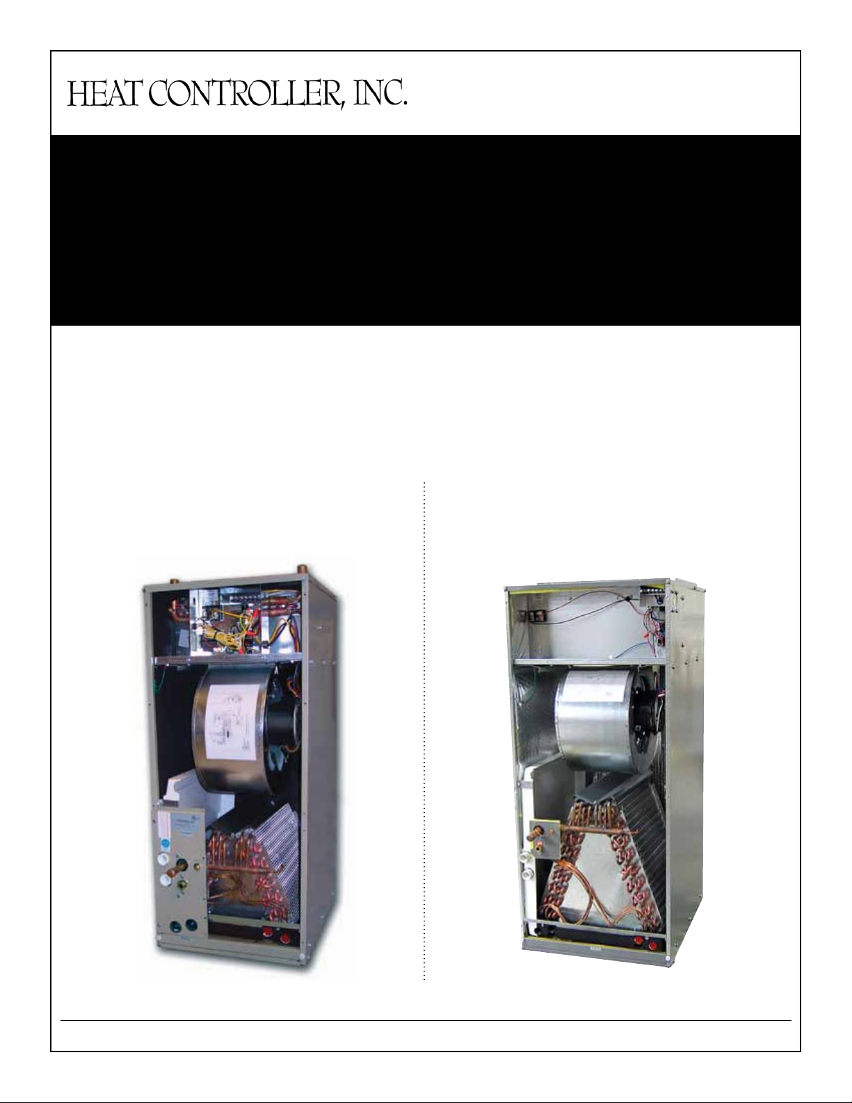
AIR HANDLERS:
Variable Speed
AHGV Hydronic
Air Handler
HAGV Electric
Air Handler with
Optional Heat
Heat Controller, Inc. • 1900 Wellworth Ave. • Jackson, MI 49203 • (517)787-2100 • www.heatcontroller.com
Page 2

1 Variable Speed Air Handlers Installation & Owners Manual
Table of Contents
Unit Nomenclature .................................2
General Information ...............................3
Inspection ...............................................3
Reference ...............................................3
Limitations .............................................3
Location .................................................3
Installation/Operation Safety Rules .......4
Unpacking ..............................................4
Clearances ..............................................4
Arrangement ..........................................4
Upow....................................................5
Horizontal ..............................................5
Control Wiring .......................................5
ECM Blower Motor ...............................5
Hot Water Piping ....................................6
Condensate Piping .................................6
Check / Test / Start Up ...........................7
Unit Shutdown .......................................7
Maintenance ...........................................7
Electrical Data ........................................8
AHGV Hydronic Performance Data ......9
Blower Performance ECM 2.3 .............10
HAVG Dimensional Data ....................11
AHGV Dimensional Data ....................12
Power Wiring .........................................5
Heat Controller, Inc. • 1900 Wellworth Ave. • Jackson, MI 49203 • (517)787-2100 • www.heatcontroller.com
Page 3
Installation & Owners Manual Variable Speed Air Handlers 2
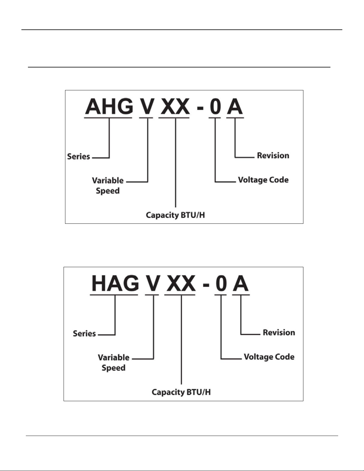
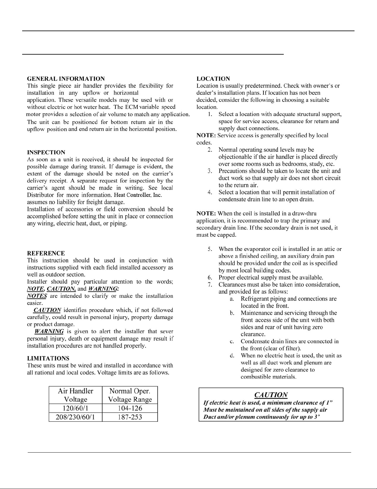
Unit Nomenclatures
AHGV:
HAGV:
Heat Controller, Inc. • 1900 Wellworth Ave. • Jackson, MI 49203 • (517)787-2100 • www.heatcontroller.com
Page 4
3 Variable Speed Air Handlers Installation & Owners Manual
Air Handler Installation Instructions
Electric and Hydronic
Heat Controller, Inc. • 1900 Wellworth Ave. • Jackson, MI 49203 • (517)787-2100 • www.heatcontroller.com
Page 5

Installation & Owners Manual Variable Speed Air Handlers 4
Air Handler Installation Instructions
Electric and Hydronic
INSTALLATION/OPERATION SAFETY RULES:
1. Read these rules and instructions carefully.
Failure to follow these rules and the installation
instructions could cause a malfunction of the unit,
and a possible safety hazard. Keep these
instructions nearby the unit for future reference.
2. While this unit has been designed and
manufactured to comply with National codes, it is
the installer’s responsibility to install this unit to
comply with Nationa
local codes and regulations. HCI assumes no
responsibility for units installed in violation of
any code or regulation.
3. Before servicing, allow unit to cool.
WARNING
ELECTRICITY WHEN WORKING ON UNIT.
This will prevent any electrical shocks or burns.
4. Ground the unit to prevent electric shock. All
electrical wiring should be in accordance with the
National Electric Code.
5. Duct work must be installed in accordance with
the standards of the National Fire Protection
Association (NFPA) for the installation of Air
Conditioning, Warm Air Heating and Ventilating
Systems (NFPA 90A
non-conditioned spaces must be insulated to
prevent formation of condensate and for
maximum efficiency.
6. The safety testing agency labels appear on the
unit’s cover and t h e factory installed coil (if
provided) only. It does not cover any other
equipment. Exterior surface of cabinet may sweat
when units is installed in a non-conditioned space
such as an attic or garage. Installer must provide
protection such
all units installed in a non-conditioned space to
prevent damage from condensation runoff. It is
recommended that units installed in nonconditioned spaces be insulated with 1” thick
fiberglass with the vapor barrier on the outside.
7. While designed to operate quietly when properly
installed, several steps should be taken insure this.
Use of isolation pads when mounting unit,
flexible d
acoustical duct liners are all good installation
practices that promote quite operation.
: ALWAYS SHUT OFF
uct collars for discharge, and use of
l codes and/or prevailing
and 90B). Duct work in
as full size auxiliary drain pan on
8. Cabinet insulation is rated for R-4.2 (standard).
Some jurisdictions require R-6.0 on installations
in a non-conditioned space. To achieve R-6.0,
add insulation 1” thick to exterior of the unit
to comply in these jurisdictions, putting the
vapor barrier on the outside.
WARNING:
Hot water can scald. Water heated to a temperature
which will satisfy space heating can scald and
permanently injure a person upon contact. Some people
are more likely to be permanently injured by hot water
than others. These include the elderly, children, the
infirm, physically or mentally handicapped.
Check local, State, and National codes requiring a
certain temperature water at the hot water tap. Special
precautions must be used in addition to us
possible temperature setting that satisfies your hot water
needs. A Tempering device such as a mixing valve,
should be used at the hot water taps, or water heater.
UNPACKING THE UNIT:
The unit should be unpacked on receipt and if any damage
is found, follow the instructions under the “INSPECTION”
section of this manual.
This air handler is completely assembled. (NOTE: Electric
heat can be ordered as field installed, if field
installed, refer to the sep
provided with the heater kit.) Only electrical power,
thermostat wiring, hot water piping (if applicable) and
duct connections are needed for installation. DX coils will
also require refrigerant and condensate drain connections.
Some units may have motor supports over the motor shaft.
Remove these supports as necessary.
MINIMUM CLEARENCES:
These units have a 0” minimum clearance to combustible
als rating from all cabinet surfaces. The unit should
materi
be installed with serviceability clearance of 30” from the
front of the unit. The unit can be serviced entirely from the
front, including replacing the filter. Be sure to route
primary and secondary condensate drain piping so that it
does not obstruct replacement of the filter.
ARRANGEMENT:
Unit is shipped from the factory for installation in a vertical
upflow or horizontal right to left air flow position
(standard) or field convertibl
to right air flow position.
arate installation instructions
e to a horizontal left
ing the lowest
Heat Controller, Inc. • 1900 Wellworth Ave. • Jackson, MI 49203 • (517)787-2100 • www.heatcontroller.com
Page 6

5 Variable Speed Air Handlers Installation & Owners Manual
Air Handler Installation Instructions
Electric and Hydronic
UPFLOW APPLICATION:
In an upflow installation the discharge outlet is at the top.
Care should be taken to insure unit is level to permit
proper condensate drainage. Normal upflow installation
will be in a closet or basement. If installed in a closet, the
closet should have a platform framed in, with an opening
at the top of the platform centered in the closet. Connect
the supply air outlet to a plenum. Install
from outside the closet to space below the platform.
Platform must be at least 12” above the floor. If installed
in a basement, run supply and return duct work in
accordance with local codes.
HORIZONTAL APPLICATION:
Horizontal applications will normally be used in an attic or
crawl space. This type of installation requires a return air
duct be attached to the unit inlet. The opposite end of the
return air d
the ceiling or wall. Remove air filter from unit if filter
grille is used. The unit is shipped in right to left
configuration. For left to right applications (before
connecting drains, refrigerant or water piping) remove coil
and doors and move horizontal pan to right side. Reinstall
coil and doors.
CAUTION:
It is mandatory to use an emergency auxiliary drain
with any coil or air
a finished ceiling.
ELECTRICAL WIRING:
Refer to the unit nameplate for specific electrical data.
uct is attached to a return air filter grille through
handler installed in an attic or above
return air grilles
pan
NOTE: See unit for complete wiring diagram located on
blower housing.
CONTROL WIRING:
Field connections to the low voltage leads are made using
appropriate field supplied wiring connectors. Consult
installatio
specific information on control wiring. Use 18 AWG
minimum copper conductors for control wiring up to 50’
between units. 16 AWG control conductors are
recommended for lengths between 50’ and 100’. Class 2
wiring is acceptable.
transformer burnout could result. Some manufacturer’s
outdoor units are equipped with a 24 volt control
transformer. If this type of outdoor unit is used with this
air handler, use a thermostat with isolating contacts to
prevent inter-connection of two separate Class 2 circuits.
Set thermostat heat anticipator at 0.15 amps for units
12KW or smaller, set at .30 amps for 15 KW and larger.
VARIABLE SPEED MOTORS:
Electronic commutated and constant torque motor
factory programmed and cannot be re-programmed in the
field. ECM motors have (4) jumper settings.
Refer to blower perform ance data located in the spec sheet
for the particular product to select the tap setting that best
fits the application
NOTE: All 208/230 volt motors are factory programmed
for “0” second fan “ON” delay for use with electric heat.
Motor must energize with electric heat. All 115 volt
motors are factory programmed for “30” second fan “ON”
delay for use with hydronic heat.
n instructions provided with accessory items for
Take care not to short control leads as,
s are
CAUTION:
Disconnect power at main fuse or circuit breaker
distribution panel before wiring unit to prevent shock or
fire hazard.
POWER WIRING:
Unit is suitable for use with copper conductors. Tighten all
wire connectors. Take care not to damage heater ceramic
insulators on electric heat models. For correct
size see unit nameplate and field wiring table inside
electrical compartment door. Use 75°C minimum wire in
unit wiring compartment. Units larger than 10 KW will
require multiple sets of power conductors.
field wire
Heat Controller, Inc. • 1900 Wellworth Ave. • Jackson, MI 49203 • (517)787-2100 • www.heatcontroller.com
Page 7

Installation & Owners Manual Variable Speed Air Handlers 6
Air Handler Installation Instructions
Electric and Hydronic
PIPING:
HOT WATER PIPING FOR HYDRONIC AHGV UNITS:
HOT WATER PIPING:
If a residential water heater is used for space heating water,
do not exceed a distance of 70’ between the air handler and
the water heater. The water heater should be the quick
recovery type. Air handler and water heater must be
located indoors and not subject to freezing temperatures.
WARNING:
Air handler must be located so that if any connections
should leak, water will not cause damage to the adjacent
area. When such locations can’t be avoided, a suitable
drain pan should be installed under the air handler, not
over 1-1/2” deep, with minimum length and width at least
2” greater than the air handler dimensions and
connected to an adequate drain. Under no circumstances
is the manufacturer to be held libel for any water damage
in connection with this air handler.
Total piping should not exceed 140’. All piping should be
¾” copper or approved PVC. It is recommended that the
water shut-off valve for the water heater be located close
to the water heater. Isolation valves are also
recommended.
It is recommended that any devices installed, which could
create a closed system, have a by-pass and/or the system
have an expansion tank to relieve the pr
thermal expansion in the water system.
essure built up by
CONDENSATE DRAIN PIPING:
The air handler “
female primary and two secondary connections (left or
right hand). Horizontal pan has two ¾” NPT female, one
primary and one secondary. Piping from each fitting used
is to have 1-1/2 minimum trap and each run in such a
manner as to provide enough slope for adequate drainage
to a visible area. Do not pipe these two fittings together
into a common drain. Cap unused connection.
AIR FILTER:
A clean, appropriately sized filter must be used or system
damage will occur. Filters are not supplied with this air
handler, a field installed filter accessory is available.
A” coil drain pan has two ¾” NPT
PVC PIPE
Typical Condensate Traps
WARNING:
Toxic chemicals such as used for treatment of boilers or
non-potable water heating appliances shall never be
introduced into a potable water space heating system.
WARNING:
When the system required water at temperatures higher
than required for other uses, a means such as a mixing
valve shall be installed to temper the water for those uses
in order to reduce the scald hazard potential.
After piping has been installed, allow the system to fill
with water and check connections for leaks. To insure
complete filling of the system, follow start-up procedure.
Heat Controller, Inc. • 1900 Wellworth Ave. • Jackson, MI 49203 • (517)787-2100 • www.heatcontroller.com
Page 8

7 Variable Speed Air Handlers Installation & Owners Manual
Single Piece Air Handler Installation Instructions
Electric and Hydronic
CHECK TEST AND START UP:
HAGV UNITS: Air handler with optional electric heat
The unit should be tested after the system has been
completely installed to determine proper operation. Unit is
equipped with heater time delay controls. If electric
heater is field installed, all heating elements should turn on
within one minute.
NOTE:
Circuit breakers are equipped with a visual “visi-trip” red
flag indicator. If red indicator shows that circuit breaker
has tripped, this indicated that a problem exists in your
system which should be corrected before re
breaker.
AHGV UNITS: Hydronic air handler
NOTE:
Heating system should not be switched on until system is
filled and hot water coil vented.
1. Fill and pressurize the water heater and air
handler.
2. The water heater should be started.
3. Vent air from the water tank by opening a hot
water spigot.
4. Vent and flush the supply and return lines by
attaching a hose to the volume purge valve and
running purge water to a safe location. Run
approximately 5 gallon
rate to purge.
5. Energize the unit by switching on the line voltage
source and the thermostat. The fan and pump
should start simultaneously. The water coil should
become warm after a few minutes of operation.
6. Units are rated at temperatures of 130° -180° F.
Set water source temperature at design
temperature and take proper safeguards for water
usage at supply points as per local codes and
safety considerations.
s of water at a high flow
:
setting
SYSTEM SHUT-DOWN:
For short periods of time during freezing temperatures if
:
the system is to be left unused, to prevent freezing of the
air handler and piping, do the following: Do not turn the
system off and leave the air handler’s thermostat on in heat
mode. If the water heater and air handler must be shut
down for extended periods, a qualified service technician
should insure that the air handler and co
drained of water.
PERIODIC MAINTENANCE:
The filter must be changed monthly to permit proper
airflow for safe and efficient operation. All other
maintenance should be performed by a licensed
technician.
il are completely
Heat Controller, Inc. • 1900 Wellworth Ave. • Jackson, MI 49203 • (517)787-2100 • www.heatcontroller.com
Page 9

Installation & Owners Manual Variable Speed Air Handlers 8
ELECTRICAL DATA
Heat Controller, Inc. • 1900 Wellworth Ave. • Jackson, MI 49203 • (517)787-2100 • www.heatcontroller.com
Page 10

9 Variable Speed Air Handlers Installation & Owners Manual
HYDRONIC PERFORMANCE DATA
Heat Controller, Inc. • 1900 Wellworth Ave. • Jackson, MI 49203 • (517)787-2100 • www.heatcontroller.com
Page 11

Installation & Owners Manual Variable Speed Air Handlers 10
BLOWER PERFORMANCE DATA
Heat Controller, Inc. • 1900 Wellworth Ave. • Jackson, MI 49203 • (517)787-2100 • www.heatcontroller.com
Page 12

11 Variable Speed Air Handlers Installation & Owners Manual
HAGV Dimensioal Data
Air Handler with Optional Electric Heat
DIMENSIONS (inches)
MODELS A B C D E F G H J K L M N P R
HAGV24-00-1A
HAGV36-00-1A
HAGV48-00-1A
HAGV60-00-1A
* All dimensions are approximate
21.00 48.00 21.00 19.00 12.50 14.50 13.00 6.75 20.00 17.00 12.75 10.30 2.30 4.35 5.00
24.50 58.75 21.75 23.35 21.25 19.75 17.25 6.75 26.00 23.00 16.75 14.35 2.30 4.35 4.50
*
Heat Controller, Inc. • 1900 Wellworth Ave. • Jackson, MI 49203 • (517)787-2100 • www.heatcontroller.com
Page 13

Installation & Owners Manual Variable Speed Air Handlers 12
AHGV Dimensioal Data
Hydronic Air Handler
DIMENSIONS (inches)
MODELS A B C D E F G H J K L M N P R S T U
AHGV24/36
AHGV48/60
* All dimensions are approximate
Heat Controller, Inc. • 1900 Wellworth Ave. • Jackson, MI 49203 • (517)787-2100 • www.heatcontroller.com
21.00 48.00 21.00 19.00 15.00 14.50 13.00 6.75 20.00 17.00 13.00 10.30 2.30 4.35 3.75 1.75 2.50 1.50
24.50 58.75 21.75 23.50 15.75 19.75 17.25 6.75 26.00 23.00 16.75 14.35 2.30 4.35 3.50 1.50 2.25 1.25
*
Page 14

6/2009
 Loading...