

Heartland pcAmerica Magellan SL Configuration And Programming Manual

One Blue Hill Plaza, 16th Floor, PO Box 1546
Pearl River, NY 10965
1-800-PC-AMERICA, 1-800-722-6374
(Voice) 845-920-0800 (Fax) 845-920-0880
Magellan SL (Single Cable)
Configuration and Programming
Guide
This document covers installing the Magellan SL (Single Cable) including:
Hardware Connections
Magellan Programming
Testing Communication Through Windows
CRE Configuration
o CRE Configuration: Inventory Configuration
Additional Magellan Programming
Usage Guide
1 | P a g e
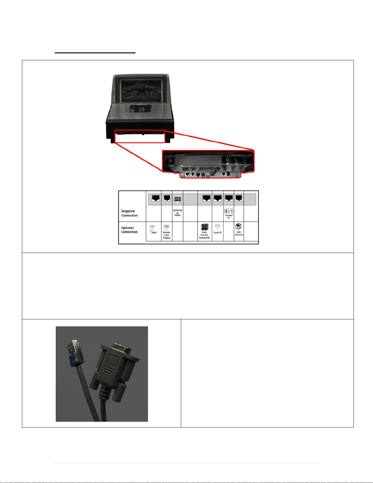
Hardware Connections
1. The Required Connection section above shows the connections that are required to make the scale operate:
The power cord will connect to the port labeled DC Power.
The data communication cord will connect to the port labeled Scanner I/F.
2. The Optional Connection section above shows the options that are available with CRE/RPE:
The scale pole display will connect to the Remote Scale Display port.
3. The data cable for the scale (pictured left) is required to
connect the scale to the computer.
2 | P a g e
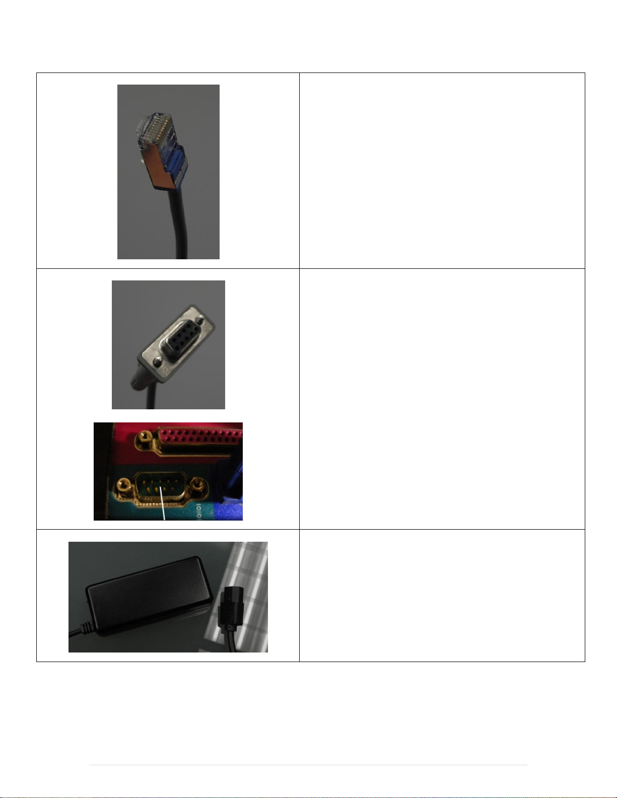
4. Connect the end (pictured left) to the underside of the
scanner/scale in the port marked Scanner I/F.
5. Plug the other end of the serial data cable into the
available serial port labeled COM1 on your computer.
Note: This device will only work while connected to COM1 of
your computer.
6. Connect the standard power cable to the power supply.
3 | P a g e
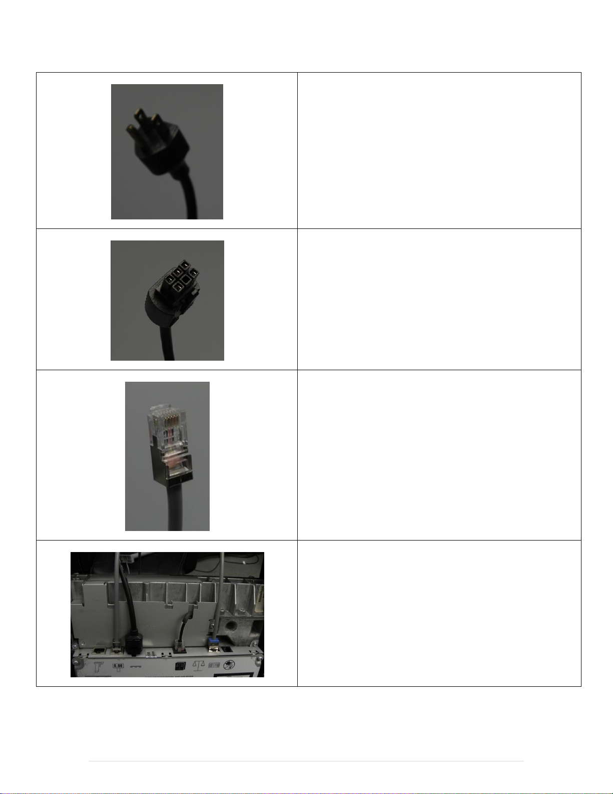
7. Connect the other end to a power wall outlet.
8. Connect the cable end (pictured left) from the power
supply into the port marked DC Power on the
scanner/scale.
9. If you have the optional pole display for the scale plug
the end (pictured left) into the Remote Scale Display
port.
10. When finished connecting the cables to your
scanner/scale place the device back to the normal
operating position.
4 | P a g e
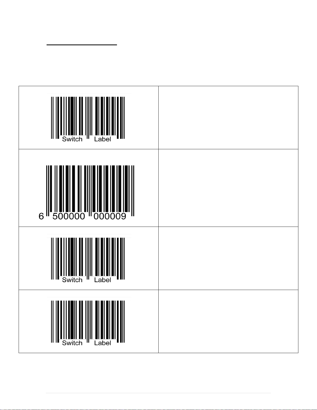
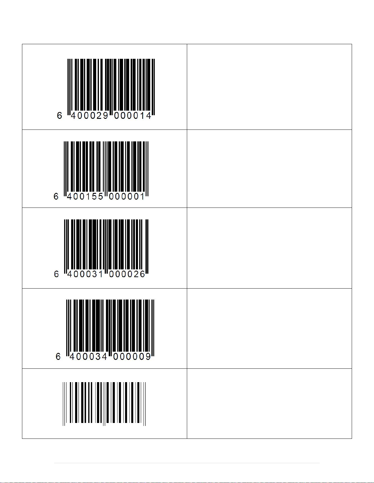
Magellan Programming
When this barcode is scanned the green light on the top
of the scanner/scale will start flashing – This will make
the scale enter the programming mode.
When this barcode is scanned there will be an audible
Beep from the scanner/scale, confirming that it scanned
correctly. This barcode will erase any settings that have
been configured on the device so that we can program it
correctly.
When this barcode is scanned the scanner will reboot and
the green lights on the top of the scanner/scale will stop
flashing – This will make the scale exit the programming
mode.
When this barcode is scanned the green light on the top
of the scanner/scale will start flashing – This will make
the scale enter the programming mode.
Scan the following barcodes in order to program the device.
After making any of the following changes to the scale you will need to contact Weights and
Measures to make sure the scale are certified and weighing items properly.
5 | P a g e
When this barcode is scanned there will be an audible
Beep from the scanner/scale, confirming that it scanned
correctly. This barcode will make the scanner/scale use
the baud rate of 9600.
When this barcode is scanned there will be an audible
Beep from the scanner/scale, confirming that it scanned
correctly. This barcode will make the scanner/scale
operate with 7 data bits.
When this barcode is scanned there will be an audible
Beep from the scanner/scale, confirming that it scanned
correctly. This barcode will set the parity to Odd.
When this barcode is scanned there will be an audible
Beep from the scanner/scale, confirming that it scanned
correctly. This barcode will set the stop bits equal to 1.
When this barcode is scanned there will be an audible
Beep from the scanner/scale, confirming that it scanned
correctly. This barcode will disable label ID’s.
6 4 0 0 1 5 7 0 0 0 0 0 9
Disable Label ID's
6 | P a g e
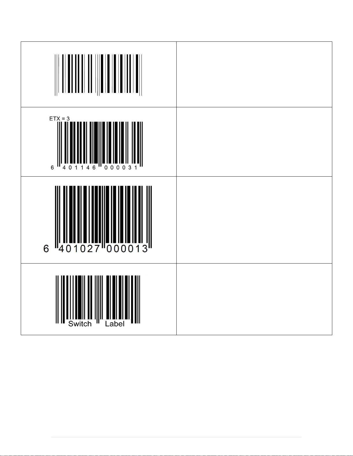
When this barcode is scanned there will be an audible
Beep from the scanner/scale, confirming that it scanned
correctly. This barcode will set the STX to a value of 2.
When this barcode is scanned there will be an audible
Beep from the scanner/scale, confirming that it scanned
correctly. This barcode will set the ETX to a value of 3.
***Only Scan this barcode if you DO NOT have the
optional Remote Display connected to the Scale (if the
optional Remote Display IS connected then skip this
barcode).***
Note: By default the remote display is enabled.
When this barcode is scanned the scanner will reboot and
the green lights on the top of the scanner/scale will stop
flashing – This will make the scale exit the programming
mode.
6 4 0 1 1 4 5 0 0 0 0 2 5
STX = 2
7 | P a g e
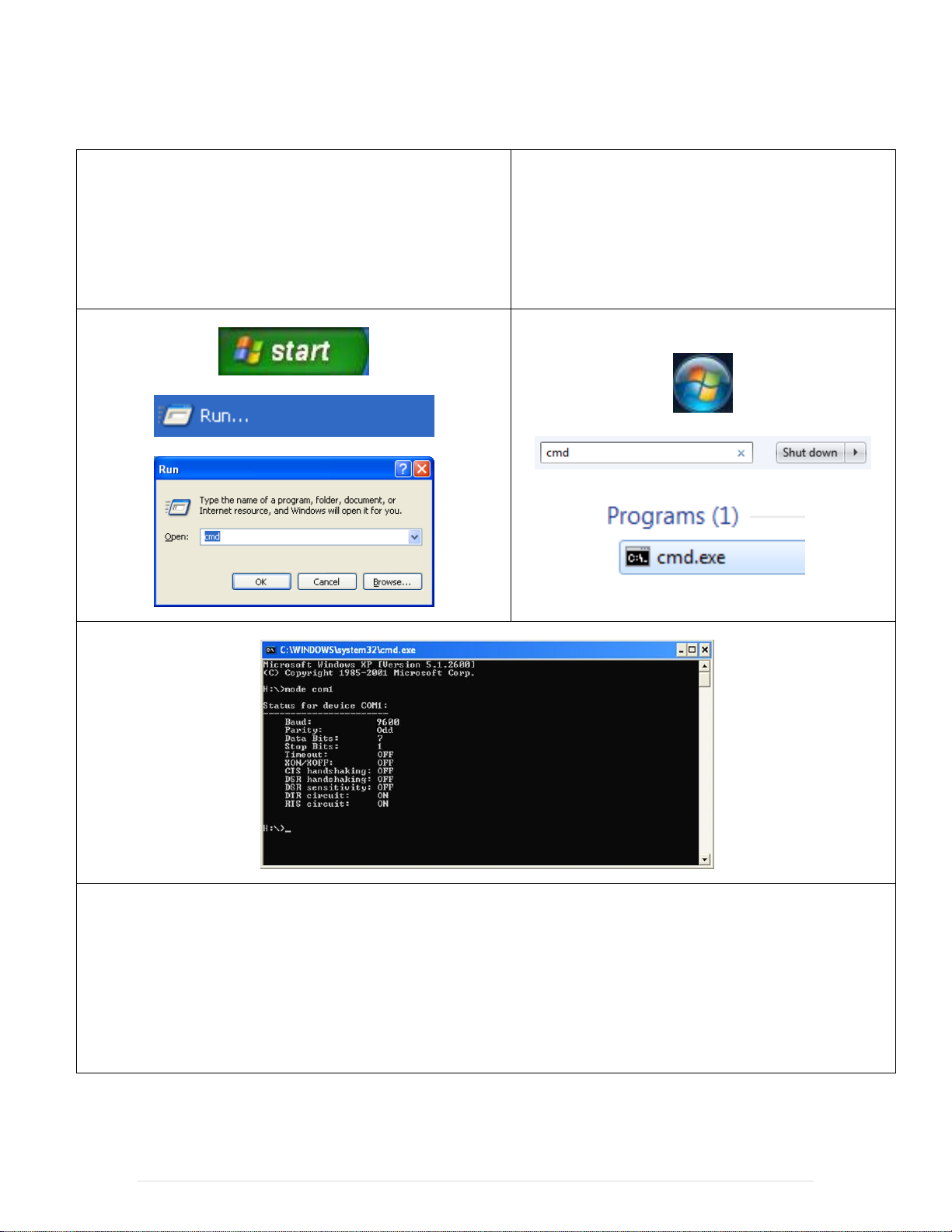
Testing Communication through Windows
In Windows XP:
1. Select Start.
2. Select Run and type in cmd. This will open the
command prompt.
In Windows 7:
1. Select Start.
2. Type in cmd. Then select cmd.exe, this will open
the command prompt.
3. At the command prompt type in: mode com1 then hit Enter.
4. You should get a message that gives information (pictured above) that shows the device is communicating with
the computer.
Note: If at the command prompt nothing is shown when typing mode com1 then there are two options:
1. We can try using a third party HyperTerminal application to test the communication of the device (Please see
the web).
2. We can try reinstalling the COM port on your computer (Please see below).
8 | P a g e
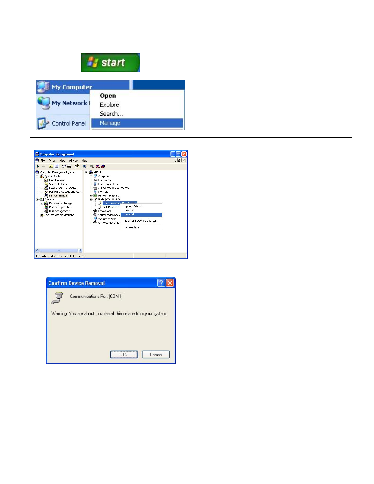
To reinstall the COM port on your computer please do
the following:
Select Start.
Right-click My Computer and select Manage.
Select the Device Manager on the left.
Open the Ports (COM & LPT) hive.
Right-click the Communications Port (COM1)
then select Uninstall.
Select OK.
9 | P a g e
 Loading...