


1050 Fountain St. N., Cambridge, Ontario, Canada N3H 4R7 ATTENTION INSTALLER: Leave this manual with appliance
Bus. (519) 650-5775 or Fax (519) 650-3773 Toll Free Phone 1-800-361-1517
Toll Free Fax 1-800-327-5609


 Model 3530-3630
Model 3535-3635
Installation and Operation Guide
30” and 36” Gas/Electric Professional Style
Cook Stove
NOTE: Clock must be set or your oven will not function!
Note: Please read these instructions thoroughly before attempting to install this unit. Failure to follow installation instructions will result in costly service calls.
This appliance can only be installed in the state of Massachusetts by a Massachusetts licensed plumber or gasfitter.
These symbols on the nameplate mean the product has been design |
® |
|
|
certified by C.S.A International Laboratories |
|
CERTIFIED |
|
C |
US |
Save these instructions for future use
© 2005 HEARTLAND APPLIANCES INC.
#3937 032205

Models 3530-3630 |


 Models 3535-3635
Installation and Operation Guide
WARNING
n All ranges can tip
n Injury to persons could result
n Install anti tip devices packed with range
nSee installation instructions
Gas Top/Electric Convection
Self Clean Models 3530/3535 & 3630/3635
CONSUMER WARRANTY
ENTIRE PRODUCT – LIMITED ONE YEAR WARRANTY
HEARTLAND warrants the replacement or repair of all parts, including gas components of this Cookstove which prove to be defective in material or workmanship, with the exception of the painted or porcelain enamel finish and plated or stainless steel surfaces, for one year from the date of original purchase. Such parts will be repaired or replaced at the option of Heartland without charge, subject to the terms and conditions set out below.
The warranty period against defects in the painted or porcelain enamel finish and plated or stainless steel surfaces, is 90 days from date of original purchase. The warranty does not include replacement of oven lamps or filters.
OVEN ELEMENTS - LIMITED SECOND THROUGH THIRD YEAR WARRANTY
HEARTLAND warrants the oven heating elements against defects in material or workmanship for an additional two years. These parts will be repaired or replaced at the option of Heartland without charge, but you pay for labour and transportation subject to the terms and conditions set out below.
TERMS AND CONDITIONS
1.This warranty applies only for single family domestic use when the Cookstove has been properly installed according to the instructions supplied by Heartland and is connected to an adequate and proper utility service.
Damage due to faulty installation, improper usage and care, abuse, accident, fire, flood, acts of God, commercial, business or rental use, and alteration, or the removal or defacing of the serial plate, cancels all obligations of this warranty. Service during this warranty must be performed by a factory Authorized Service Person.
2.Warranty applies to product only in the country in which it was purchased.
3.Heartland is not liable for any claims or damages resulting from any failure of the Cookstove or from service delays beyond their reasonable control.
4.To obtain warranty service, the original purchaser must present the original Bill of Sale, Model and Serial number. Components repaired or replaced are warranted through the remainder of the original warranty period only.
5.The warranty does not cover expense involved in making this appliance readily accessible for servicing, replacement of house fuses or fuse boxes, or resetting of circuit breakers.
6.This warranty gives you specific legal rights. Additional warranty rights may be provided by law in some areas.
7.Adjustments such as education of customer in proper use and care of product calibrations, air shutter adjustments, levelling, tightening of fasteners, or utility connections normally associated with original installation are the responsibility of the dealer or installer and not that of the Company.
8.Breakage, discoloration or damage to glass, metal surfaces, plastic components, trim, paint, porcelain or other cosmetic finish, caused by improper usage or care, abuse, or neglect is not covered under this warranty.
Fill in the spaces below for future reference, should service be required.
PLACE OF PURCHASE______________________________
DATE OF PURCHASE_______________________________
SERIAL NUMBER__________________________________
MODEL NUMBER__________________________________
If further help is needed concerning this warranty, contact:
Customer Service Heartland Appliances Inc.
1050 Fountain St. N., Cambridge, Ontario, Canada N3H 4R7
Bus. (519) 650-5775 or Fax (519) 650-3773 Toll Free Phone 1-800-361-1517
Toll Free Fax 1-800-327-5609

Table of Contents
Metro / Legacy Series
Section 1: Set Up & Assembly .................... |
2 |
|
Safety Instructions .......................................... |
2 |
|
Preparing the Installation Site ......................... |
2 |
|
Installation Clearances .................................... |
2 |
|
Exhaust Hood .................................................. |
3 |
|
Electrical Installation ...................................... |
3 |
|
Gas Line Installation ....................................... |
3 |
|
Clearance Diagrams ........................................ |
4 |
|
Preparing the Range for Installation ............... |
8 |
|
Positioning the Range ..................................... |
9 |
|
Section 2: Safety Guidelines...................... |
10 |
|
Important Safety Instructions ....................... |
10 |
|
Oven Safety ................................................... |
10 |
|
Self Clean Safety Instructions ...................... |
11 |
|
Exhaust Hood Safety .................................... |
11 |
|
Selecting the Proper Cookware .................... |
12 |
|
Section 3: Cooking Controls ..................... |
13 |
|
Cooktop Features .......................................... |
13 |
|
Oven Features ............................................... |
13 |
|
Cooking Controls Diagrams ......................... |
14 |
|
Control Panel Lay Graphic ........................... |
15 |
|
Electronic Oven Control Features ................ |
16 |
|
Section 4: Oven & Clock Operation ........ |
17 |
|
1. |
General Information .................................. |
17 |
2. |
Safety Features .......................................... |
18 |
3. |
Oven Light ................................................ |
18 |
4. |
Clock Operation ........................................ |
18 |
5. |
Minute Minder .......................................... |
20 |
6. |
Bake .......................................................... |
21 |
7. |
True Convection ....................................... |
24 |
8. |
Convection Bake ....................................... |
37 |
9. |
Broil .......................................................... |
30 |
10.Convection Broil ...................................... |
30 |
|
11.Sabbath Mode .......................................... |
32 |
|
12. Self Clean ................................................ |
34 |
|
Section 5: Top Burner & Grill Operation36 |
||
Lighting the Top Burners and Grill .............. |
36 |
|
Small Pot Ring / Trivet ................................. |
36 |
|
Section 6: Baking, Broiling & Roasting ... 37
Standard Baking ............................................ |
37 |
Standard Broiling .......................................... |
37 |
True Convection ........................................... |
38 |
Convection Bake ........................................... |
38 |
Convection Roasting ..................................... |
38 |
Convection Broil ........................................... |
38 |
Sabbath Mode ............................................... |
38 |
Broiling Tips ................................................. |
39 |
Section 7: Care & Cleaning ...................... |
40 |
Porcelain – Legacy Series ............................. |
40 |
Stainless Steel – Metro Series ...................... |
40 |
Oven Cleaning - Self Clean .......................... |
41 |
Surface Burners ............................................. |
42 |
Nickel Plated Parts ........................................ |
42 |
Oven Light Replacement .............................. |
42 |
Grill ............................................................... |
43 |
Interior Oven Rack ........................................ |
44 |
Rack Supports ............................................... |
44 |
Oven Door Removal ..................................... |
45 |
Section 8: Trouble Shooting ....................... |
46 |
Burner Set Up and Adjustment ..................... |
46 |
Problem Solver - Range Oven ...................... |
47 |
Power Failure Operation ............................... |
48 |
Gas Trouble Shooting .................................... |
48 |
Gas Trouble Shooting Chart .......................... |
49 |
Section 9: Reference .................................. |
50 |
Accessories ................................................... |
50 |
Conversion Kits and Information ................. |
50 |
Parts Drawing ............................................... |
51 |
Parts Description ........................................... |
52 |
Heartland Kitchens ....................................... |
53 |
Appendix A: Cooking Guides ................... |
56 |
Meat Roasting Guide .................................. |
iii |
Poultry Roasting Guide ............................... |
iv |
Broiling Guide ............................................ |
v |
Baking Guide ............................................. |
vi |
Grilling Guide ............................................. |
vii |
Metro / Legacy Series
Set Up and Assembly
Safety Instructions
Please check for any damage that may have occurred during shipping. In the unlikely event that you find any shipping damage, inform your dealer immediately!
Legacy and Metro ranges consist of the range body and the splashback. The splashback is fastened to the back of the stove for shipping purposes.
Tools required for assembly:
•Screwdriver
•Utilityknife
•Level
•Metal shears
•Hammer
You must have a qualified electrician connect the new range to be sure all electrical codes and regulations are observed except when range is equipped with a cord and plug. A qualified gas technician must install this appliance to ensure local installation codes and regulations are observed.
Preparing the Installation Site
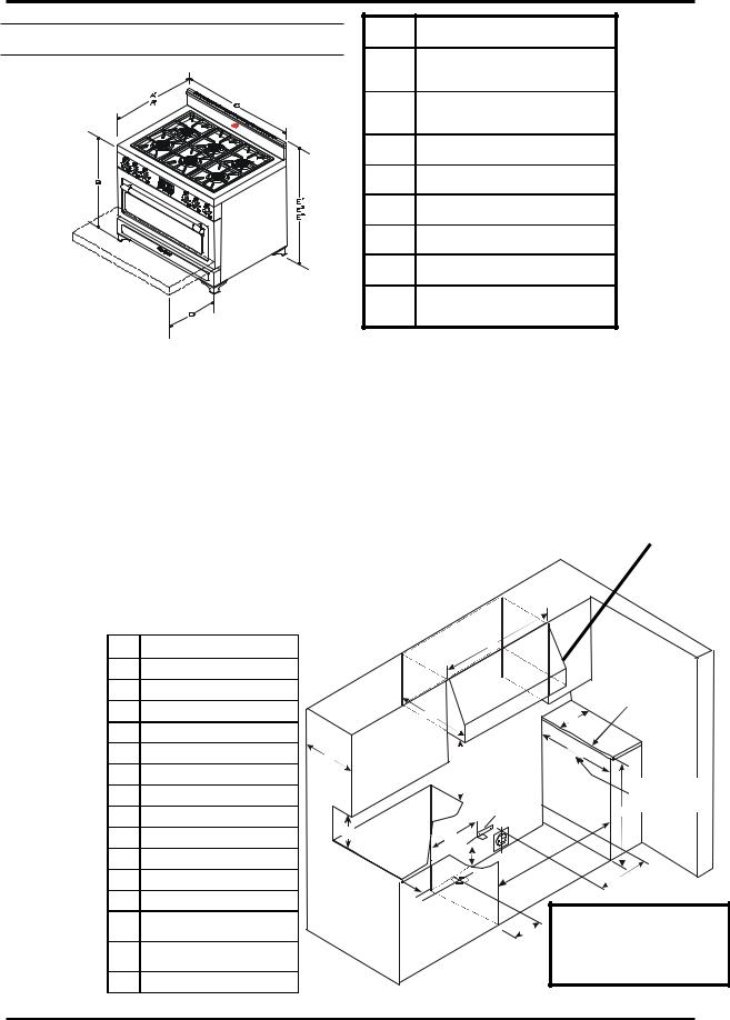
Find the appropriate clearance/installation diagram for your range on the following pages. (see fig 1 & 2) Diagrams include installations with an exhaust hood.
These diagrams will outline the required opening for your range and clearances to cupboards, electrical outlets, and gas outlet. Site preparation can be made to have these utilities ready prior to receipt of the range and splashback. Also required before installation of your range, is the placing of the Anti -tip bracket.
Follow this procedure to install the anti tip
bracket.
1)the anti tip bracket package (complete with screws) is found in the accessory box inside the oven.
2)on the wall measure up from the floor 5 5/8” and mark that position with a pencil, this is the correct height of the tab on the bracket.
3)at the 5 5/8” height locate a wall stud along that horizontal plane.
4)fasten the bracket to the wall stud at the 5 5/8 height with the 2 screws supplied.
5)use the two holes immediately above the tab in the left side of the bracket, if there is a blockage preventing the use of these holes, use the alternate holes in right side of the bracket.
use these holes to mount bracket
alternate mounting holes
this tab fits over the bottom panel of the appliance, when the appliance is slid into place.
Installation Clearances
Should the range be installed adjacent to a refrigerator, it is important that there be a minimum of 5” (30 cm) of space between the two appliances for proper air circulation.
Installation of cabinet storage space above the surface burners should be avoided at all costs to eliminate the risk of burns or fire by reaching over the surface burners. If combustible materials are present above the cooking surface they should be at a minimum distance of 36” from the surface burners.
2

Section 1: Set Up and Assembly
Your range should be level for best cooking results. To verify, place a carpenter’s level on top of the cooking surface and across the oven rack. If leveling is required, adjust the leveling screws under one or more of the legs accordingly. (see “Positioning the Range” step in this section)
To facilitate the installation of your range, all four legs areequippedwithTeflongliders. Topreventscratches ensure that the gliders and kitchen floor are free of any debris.
Exhaust Hood
An exhaust hood must be installed over your new appliance. (see fig 1) Matching Legacy and Metro exhaust hoods are available from your dealer. You mayalsocallHeartlandAppliancesdirectlyforpricing information. Our hoods are designed and built to complement your range’s visual appeal and perform ance.
Should you wish to install an exhaust hood of your ownchoice,ensurethattheexhausthoodyoupurchase is the correct size and capacity for your Heartland range. Please follow the exhaust hood manufacturers installationinstructions. Wheninstallinganaftermarket exhaust hood over a Heartland appliance we recommend that you use the clearances as shown in the clearance diagrams for exhaust hood installations.
Venting Safety Guidelines:
Installation must be completed in accordance with all local and national codes. Use only materials which conform to local codes in effect. Be sure the power is disconnected before doing any electrical work. All duct work must be metal. Do not use plastic duct. The range hood should never be exhausted into a wallcavityoranatticwhereanaccumulationofgrease could become a fire hazard. When the installation is completed, turn on the fan and make sure that there are no obstructions in the line.
Electrical Installation
Electrical requirements: standard 240 60 Hz (4.5 Kw for 30” models and 5.6 Kw for 36” models) volt receptacle,properlypolarized,onit’sownline.Ranges are provided with a moulded on plug cap power cord rated 120/240 volts
Models 3520/3525 and 3620/3625 gas/electric ranges must be electrically grounded in compliance with local codes. In the absence of local codes, the installationmustconformwiththeNationalElectrical
Code.Disconnecttheelectricalsupplybeforeservicing the appliance.
Gas Line Installation
Gas requirements: 30” and 36” models can be operatedwitheithernaturalgasorliquidpropane(LP). The ranges are set for either natural gas OR propane at the factory. A conversion kit may be purchased at a later time and installed on site should the need arise. The appliance requires a ½” NPT connector. Use only approved pipe. Check that your range is correctlyinstalledbyaqualifiedtechnicianorinstaller for the type of gas used.Use minimum 5/8” diameterflexibleline.
The range must be installed in compliance with local codes. In the absence of local requirements, the installationmustconformwiththeNationalGasCode.
Note: Appliances installed in the state of Massachusetts: - This appliance can only be installed in the state of Massachusetts by a Massachusetts licensed plumber or gas fitter-This appliance must be installed with a three (3) foot / 36 inch long flexible gas connector. A “T” handle type manual gas valve mustbeinstalledinthegassupplylinetothisappliance
During any pressure testing of the gas supply piping system, at test pressures equal to or less than 2.5 KPS, the appliance must be isolated from the gas supplypipingsystembyclosingitsindividualmanual shutoffvalve.
The maximum propane/natural gas supply inlet pressure must not exceed 14” of water column. The minimumgassupplyinletshouldbeatleast6”ofwater column for natural gas or at least 11” of water column for LP gas.
3
Metro / Legacy Series
Clearance Diagrams - 36” Metro Dim |
36" Metro |
|
A1 |
28 3/4" (73cm) |
|
to front of stove |
||
|
||
A2 |
31 1/4" (79cm) |
|
to edge of oven door handle |
||
|
||
B |
36" 1/8 (92cm) |
|
C |
36" (91cm) |
|
D |
17 1/2" (79cm) |
|
E1 |
standard 40 5/8" (103cm) |
|
E2 |
low profile: 38" (97cm) |
|
E3 |
high back , high back w/shelf: |
|
56 1/8" (143cm) |
||
|
||
Figure 1 |
Table 1 |
Clearances
•Oven door vents must be 2" from any combustible. Door vents are required on Metro units to allow oven door ventilation.
•Minimum distance between the range and a side wall above the cooking top surface is 6” (see dim "O" in Table 2 below)
•0” Clearance to the back of the stove may be obtained when installing the appliance against a non - combustible wall or with the installation of our Splashback Kit. Responsibility for ensuring that the rear wall is non - combustible lies with the owner or end user. (check local building codes) - if wall behind stove is deemed combustible and our splashback kit is not installed, then the minimum spacing from the back of stove to nearest combustible wall is 6”
Electrical requirements: |
|
|
|
• Electrical hookup must be done by a licenced electrician |
For proper performance a 900 CFM vent |
||
• 240 Volts 60Hz 5.6 kW |
3 prong plug for U.S. and 4 prong for Canadian installations. |
||
hood is required on all 36" Metro ranges |
|||
(5 ft-1.5 m power cord included) New installations for the U.S. may require a four prong |
to ensure adequate and proper ventilation. |
||
plug, please confirm prior |
to ordering. |
For superior ventilation we recommend |
|
Gas Requirements: |
|
using a 42” hood, however a 36” hood is |
|
• Gas hook-up must be done by a licensed gas fitter. |
adequate. |
||
• Pressure requirements: Natural gas: 6” W.C. (min); LP |
|
||
|
|||
gas: 11” W.C. (min) |
|
|
|
• Connection: 1/2” |
|
|
|
NPT |
• 5/8” minimum |
Dim |
36" Metro |
|
|
|
|
|
|
|
||
diameter flex line. |
G |
25 1/2" (65cm) |
|
|
|
Q |
|
|
|
|||
• |
An |
accessible |
H |
36" (92.5cm) |
|
|
|
|
|
|
|
|
manual shut off valve |
|
|
|
|
|
|
|
|||||
|
|
|
|
|
|
|
|
|
||||
must be installed at |
I |
12" (30.5cm) |
|
|
|
|
|
Edges of |
|
|||
the appliance. |
|
J |
37" (94cm) |
* |
|
|
|
|
counter top |
|
||
|
|
|
R |
|
m ust be finished |
|
||||||
|
|
|
|
|
|
|
|
|
|
|
||
• |
Natural Gas/Pro- |
|
|
|
|
|
O |
|
|
|||
K |
5 5/8"(14.5cm) |
|
|
|
|
|
|
|||||
pane Conversion kits |
|
|
|
|
|
|
|
|||||
|
|
|
|
|
|
|
|
|
||||
are available - must |
L |
2" (5cm) |
|
P |
|
|
G |
|
|
|||
|
|
|
|
|
|
|
||||||
be done by a licensed |
M |
18" (38cm) |
|
|
S |
|
|
|
||||
|
|
|
|
|
|
|||||||
gas fitter |
|
N |
20" (51cm) |
|
|
|
S 1 |
|
cupboard depth |
|||
Anti Tip Bracket: |
|
|
|
|
|
|||||||
O |
|
|
|
|
Anti-tip |
|
m ust not exceed |
|||||
bracket included with |
6" (6cm) min left and right side |
|
|
|
H 26” |
|
||||||
|
|
bracket |
|
|
||||||||
every stove. |
When |
P |
13" (33cm) |
|
|
T |
N |
|
|
|
||
properly installed, will |
|
|
|
|
|
|
|
|||||
Q |
SPECIFY WIDTH OF HOOD |
|
|
J |
|
|
||||||
prevent stove from tip- |
|
|
K |
|
|
|||||||
R |
24" (61 cm) |
|
|
|
|
|
|
|
||||
ping forward if down- |
|
|
|
|
|
|
|
|||||
|
|
|
|
|
|
|
M |
|
||||
ward force is applied |
S |
30" (76cm) min - 36" (92 cm) |
|
|
|
|
|
|||||
|
|
G as Inlet |
|
|
|
|||||||
to an open door. |
|
for standard and high back guard |
|
|
Note: If range must stand |
|||||||
|
30" (76 cm) min - |
|
|
|
L |
|||||||
|
|
|
|
|
|
|
|
beside a |
refrigerator, it |
is |
||
|
|
|
|
S1 |
33 1/2" (85cm) max. |
|
|
|
||||
|
|
|
|
|
|
I |
important |
for proper |
air |
|||
|
|
|
|
|
for low profile back guard only |
|
|
|||||
|
|
|
|
T |
|
|
|
|
|
circulation.There must be at |
||
|
|
|
|
18" (45cm) |
|
|
|
|
least 5” (125 mm) of space |
|||
|
|
Table 2 |
|
* U.S. models only: J=36 1/2” |
|
|
Figure 2 |
between the two appliances. |
||||
|
|
|
|
|
|
|
|
|||||
4
|
|
|
Section 1: Set Up and Assembly |
Clearance Diagrams - 30” Metro |
Dim |
30" Metro |
|
|
|
A1 |
28 3/4" (73cm) |
|
|
to front of stove |
|
|
|
|
|
|
|
A2 |
31 1/4" (79 cm) |
|
|
to edge of oven door handle |
|
|
|
|
|
|
|
B |
36 1/8" (92cm) |
|
|
C |
29 3/4" (76cm) |
|
|
D |
17 1/2" (45cm) |
|
|
E1 |
standard 40 5/8" (103cm) |
|
|
E2 |
low profile: 38" (97cm) |
|
|
E3 |
high back w/shelf: |
|
|
56 1/8" (143cm) |
|
|
|
|
|
Clearances |
Figure 1 |
|
Table 1 |
|
|
|
|
•Oven door vents must be 2" from any combustible. Door vents are required on Metro units to allow oven door ventilation.
•Minimum distance between the range and a side wall above the cooking top surface is 6” (see dim "O" in Table 2 below)
Electrical requirements:
•Electrical hookup must be done by a licenced electrician
•240 Volts 60Hz 4.1 kW three prong plug for U.S. and four prong for Canadian installations. (5 ft-1.5 m power cord included) New installations for the U.S. may require a four prong plug, please confirm prior to ordering.
Gas Requirements:
•Gas hook-up must be done by a licensed gas fitter.
•Pressure requirements: Natural gas: 6” W.C. (min); LP gas: 11” W.C. (min)
• Connection: 1/2” NPT • 5/8” minimum diameter flex line.
•An accessible manual shut off valve must be installed at the appliance.
•Natural Gas/Propane Conversion kits are available - must be done by a licensed gas fitter
For proper performance a 450 CFM vent hood is required on all 30" Legacy ranges to ensure adequate and proper ventilation. For superior ventilation we recommend using a 36” hood, however a 30” hood is adequate.
Anti Tip Bracket:
When properly installed, will prevent stove from tipping forward if downward force is applied to an open door.
bracket included with every stove.
Dim |
30" Metro |
|
|
Q |
|
|
|
|
|
|
|
||
G |
Maximum 26"" (66cm) |
|
|
|
Edges of |
|
|
|
|
|
|
|
|
H |
36" (92.5cm) |
|
|
|
counter top |
|
|
|
R |
m ust be finished |
|
||
I |
10" (25cm) |
|
|
O |
|
|
|
|
|
|
|||
|
|
|
|
|
||
J |
* |
|
|
|
G |
|
30 3/4" (78cm) |
P |
|
|
|
|
|
K |
5 5/8"(14.5cm) |
|
S |
|
|
|
|
|
|
|
|||
|
|
S 1 |
|
|
||
|
|
|
|
cupboard depth |
|
|
L |
2" (5cm) |
|
|
|
|
|
|
|
Anti-tip |
m ust not exceed |
|
||
|
|
|
|
|
||
|
|
|
|
H 26” |
|
|
M |
15" (38cm) |
|
|
bracket |
|
|
N |
10" (51cm) |
|
T |
N |
|
|
|
|
|
|
|
|
|
O |
6" (15cm) min left and right side |
|
|
K |
J |
|
|
|
|
|
|
||
P |
13" (33cm) |
|
|
|
M |
|
Q |
SPECIFY WIDTH OF HOOD |
|
|
Gas Inlet |
Note: If range must stand |
|
|
|
L |
||||
|
|
|
|
|||
R |
24" (61 cm) |
|
|
beside a refrigerator, it is |
||
|
|
|
||||
|
30" min to 36" max (76-92cm) |
|
|
I |
important for proper |
air |
S |
|
|
|
circulation.There must be |
||
|
for standard and high back guard |
|
|
|
at least 5” (125 mm) of |
|
|
|
|
|
|
||
S1 |
30" min to 33-1/2" max (76-85cm) |
|
|
|
space between the |
two |
|
for low profile back guard only |
|
|
|
appliances. |
|
T |
18" (45cm) |
|
|
|
|
|
* U.S. models only: J=30 1/4”
Table 2 Figure 2 5
Metro / Legacy Series
Clearance Diagrams - 36” Legacy |
Dim |
36" Legacy |
|
A1 |
28 3/4" (73cm) |
|
to front of stove |
|
|
|
|
|
A2 |
31 1/2" (80 cm) |
|
to edge of oven door handle |
|
|
|
|
|
B |
36 1/8" (92cm) |
|
C |
36" (91cm) |
|
D |
17 1/2" (45cm) |
|
E1 |
standard 42 1/8 "(106cm) |
|
E2 |
low profile: 38" (97cm) |
|
E3 |
high back w/ shelf: |
|
56 1/8" (143cm) |
|
|
|
|
Figure 1 |
|
Table 1 |
Clearances
•Minimum distance between the range and a side wall above the cooking top surface is 6” (see dim "O" in Table 2 below)
•0” Clearance to the back of the stove may be obtained when installing the appliance against a non - combustible wall or with the installation of our Splashback Kit. Responsibility for ensuring that the rear wall is non - combustible lies with the owner or end user. (check local building codes) - if wall behind stove is deemed combustible and our splashback kit is not installed, then the minimum spacing from the back of stove to nearest combustible wall is 6”
Electrical requirements: |
|
For proper performance a 900 CFM vent |
|
• Electrical hookup must be done by a licenced electrician |
hood is required on all 36" Metro ranges |
||
• 240 Volts 60Hz 5.6 kW |
3 prong plug for U.S. and 4 prong for Canadian installations. |
to ensure adequate and proper ventila- |
|
(5 ft-1.5 m power cord included) New installations for the U.S. may require a four prong |
tion. For superior ventilation we |
||
plug, please confirm prior |
to ordering. |
recommend using a 42” hood, however |
|
a 36” hood is adequate. |
|||
|
|
||
Gas Requirements: |
|
|
|
|
|
||
• Gas hook-up must be done by a licensed gas fitter. |
|
||
• Pressure requirements: Natural gas: 6” W.C. (min); LP gas: 11” W.C. (min) |
|
||
• Connection: 1/2” NPT |
• 5/8” minimum diameter flex line. |
|
|
• An accessible |
|
|
|
manual |
shut |
off |
Dim |
36" Legacy |
|
|
|
|
|
Q |
|
|
valve must be in- |
G |
Maximum 26"" (66cm) |
|
|
|
|
|
|
|
|||
stalled at the appli- |
|
|
|
|
|
|
|
|||||
|
|
|
|
|
|
|
|
|
Edges of |
|||
ance. |
|
|
H |
36" (92.5cm) |
|
|
|
|
|
|
|
|
|
|
|
|
|
|
|
|
|
counter top |
|||
• Natural Gas/Pro- |
I |
12" (30.5cm) |
|
|
|
R |
|
|
|
m ust be finishe d |
||
|
|
|
|
|
|
O |
||||||
pane Conversion |
|
|
|
|
|
|
|
|
||||
J |
37" (94cm) |
* |
|
|
|
|
|
|
||||
kits are available - |
|
|
|
|
|
|
G |
|||||
must be done by a |
K |
5 5/8"(14.5cm) |
|
P |
|
S |
|
|
|
|||
licensed gas fitter |
L |
2" (5cm) |
|
|
|
1 |
|
|
|
|||
|
|
|
S |
|
|
|
||||||
|
|
|
|
|
|
|
|
|
|
|
cupboard depth |
|
|
|
|
M |
|
|
|
|
|
|
|
|
|
Anti Tip Bracket: • |
18" (46cm) |
|
|
|
|
|
Anti-tip |
|
m ust not exceed |
|||
|
|
|
|
|
|
|
|
H 26” |
||||
N |
16" (41cm) |
|
|
|
|
|
bracket |
|
||||
Bracket included |
|
|
|
|
|
|
|
|
||||
|
|
|
|
T |
|
|
|
|
|
|||
with every stove. |
O |
6" (15cm) min left and right side |
|
N |
|
|
|
|
||||
|
|
K |
|
|
J |
|||||||
When properly in- |
P |
13" (33cm) |
|
|
|
|
|
|
||||
|
|
|
|
|
|
|
|
|||||
stalled, will prevent |
Q |
SPECIFY WIDTH OF HOOD |
|
|
|
|
|
|
M |
|||
stove from tipping |
|
|
|
|
|
|
||||||
|
|
|
|
|
G as Inlet |
|
|
|
||||
forward |
if down- |
R |
24" (61 cm) |
|
|
|
|
|
|
|||
|
|
|
L |
|
|
|
Note: If range must stand beside |
|||||
ward force is ap- |
|
30" min to 36" max (76-92 cm) |
|
|
|
|
|
|||||
S |
|
|
|
|
|
I |
a refrigerator, it is important for |
|||||
plied to an open |
for standard and high back guard |
|
|
|
|
|
||||||
|
|
|
|
|
|
proper air circulation.There must |
||||||
door. |
|
|
|
30" min to 32" max (76-82 cm) |
|
|
|
|
|
|
||
|
|
S1 |
|
|
|
|
|
|
be at least 5” (125 mm) of space |
|||
|
|
|
|
for low profile back guard only |
|
|
|
|
|
|
between the two appliances. |
|
|
|
|
|
|
|
|
|
|
|
|
|
|
|
|
|
T |
18" (45cm) |
|
|
|
|
|
|
|
|
* U.S. models only: J=36 1/2”
6

|
|
Section 1: Set Up and Assembly |
Clearance Diagrams - 30” Legacy |
Dim |
30" Legacy |
|
|
|
|
A1 |
28 3/4" (73cm) |
|
to front of stove |
|
|
|
|
|
A2 |
31 1/2" (80cm) |
|
to edge of oven door handle |
|
|
|
|
|
B |
36 1/8" (92cm) |
|
C |
29 3/4" (76cm) |
|
D |
17 1/2" (45cm) |
|
E1 |
standard 42 1/8" (106cm) |
|
E2 |
low profile: 38" (97cm) |
|
E3 |
high back w/shelf: |
|
56 1/8" (143cm) |
|
|
|
|
Figure 1 |
|
Table 1 |
Clearances |
|
|
• Minimum distance between the range and a side wall above the cooking top surface is 6” (see dim "O" in Table 2 below)
Electrical requirements:
•Electrical hookup must be done by a licenced electrician
•240 Volts 60Hz 4.1 kW three prong plug for U.S. and four prong for Canadian installations. (5 ft-1.5 m power cord included) New installations for the U.S. may require a four prong plug, please confirm prior to ordering.
Gas Requirements:
• Gas hook-up must be done by a licensed gas fitter.
• Pressure requirements: Natural gas: 6” W.C. (min); LP gas: 11” W.C. (min)
• Connection: 1/2” NPT • 5/8” minimum diameter flex line.
•An accessible manual shut off valve must be installed at the appliance.
•Natural Gas/Propane Conversion kits are available - must be done by a licensed gas fitter
For proper performance a 450 CFM vent hood is required on all 30" Legacy ranges to ensure adequate and proper ventilation. For superior ventilation we recommend using a 36” hood, however a 30” hood is adequate.
Anti Tip Bracket: bracket included with every stove. When properly installed, will prevent stove from tipping forward if downward force is applied to an open door.
Dim |
30" Legacy |
|
|
|
|
G |
Maximum 26" (66cm) |
|
|
|
|
H |
36" (92.5cm) |
|
|
|
|
I |
10" (25cm) |
|
|
|
|
J |
30 3/4"* (78cm) |
|
|
|
|
K |
5 5/8"(14.5cm) |
|
|
|
|
L |
2" (5cm) |
|
|
|
|
M |
15" (38cm) |
|
|
|
|
N |
10" (51cm) |
|
|
|
|
O |
6" (15cm) min left and right side |
|
|
|
|
P |
13" (33cm) |
|
|
|
|
Q |
SPECIFY WIDTH OF HOOD |
|
|
|
|
R |
24" (61 cm) |
|
|
|
|
S |
30" min to 36" max (76-92cm) |
|
for standard and high back guard |
||
|
||
|
|
|
S1 |
30" min to 32" max (76-82cm) |
|
|
for low profile back guard only |
|
T |
18" (45cm) |
|
|
|
*U.S. models only: J=30 1/4”
Q


 R
R
P
S
S1
Anti-tip bracket
T |
N |
|
 K
K


 G as Inlet
L
 I
I
Table 2
Figure 2
Edg es of counter top
m ust be finishe d
 O
O

G
cupboard depth must not exceed
H 26”
J
M
Note: If range must stand beside a refrigerator, it is important for proper air circulation.There must be at least 5” (125 mm) of space between the two appliances.
7
Metro / Legacy Series
Preparing the Range for
Installation
1.Carefully remove banding with metal shears. Caution: banding may be under pressure, wear gloves to protect hands from accidental cuts.
2.Remove crating, cardboard, and plastic packaging material. To avoid damage to the finish of the range, please use caution.
3.Remove grates, oven racks, baking trays, and accessory package from the oven. Set them aside. Oven racks and grates should be washed in warm soapy water, prior to use.
4.Remove packaging from top of burners. The burners are shipped completely assembled and are pre-adjusted for the gas setting ordered – natural gas or propane.
5.Carefully lift the range off pallet and onto the floor directly in front of the gas and electrical connections. Two people are required to lift the stove into position. In order not to damage the range, refrain from lifting by the top. Only lift the range around the bottom of the oven body – one person on each side.
6.Leg assembly.
i.Legacy.
Adjust base leveling bolts (with Teflon glider attached) so that they extend beyond the bottom of the leg by approximately 1/8”–1/4” (0.3cm-0.6cm).
Adjusting the levelling bolts in too far will cause the leg to drag on the floor. This could potentially cause damage to flooring. (see fig 4)
ii. Metro.
Legs are pre-adjusted for level. They may require only a slight adjustment.
(fig 5)
Locate the leg covers inside the oven. Unwrap and snap covers into position. (fig 5)
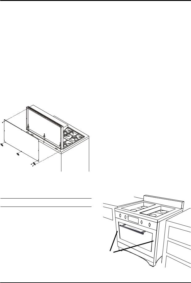
7. Assemble the splashback. (fig 6) Locate the splashback at the back of the stove. Remove screws and splashback. Do not throw these screws away – they are required to reinstall the splashback. Position splashback on range. Line up holes in the splashback with the holes at the back of the range. Using screws and screwdriver provided, assemble the splashback to the range.
(fig 4) |
(fig 6) |
|
8
Section 2: Safety Guidelines
8. If you are installing a 20” high profile backguard:
a.Unpackage.
b.Secure 20” high profile back to the stove top using:
3-large metal washers.
3-small metal washers.
3-stainless steel screws.
c.Secure back panel to the 20” high profile back using:
9-black sheet metal screws.(do not secure t he three bottom holes at this time)
d. Secure brackets (#3266-3 pcs.)to the 20” high profile back and stove top,using 6 black sheet metal screws.
8. Range is now ready for gas connection by a qualified technician/installer.
3.Caution. On flooring with very rough surfaces or deep, large grooves the appliance may have to be lifted and slowly slid into position.
4.Place both hands on the front. Carefully push the range into place. Do not forget to plug in the main power cord before the range is in it’s final position.
5.To level the range, simply adjust the levelling screws located at the bottom of each leg (as described “Preparing the Range”). Using a 5/16” (8mm) open end wrench, adjusting the screw clockwise to raise up the corner, and counter-clockwise to lower the corner. Do not forget that the Teflon glider should extend beyond the bottom of the leg by approximately 1/8”– 1/4” (0.3–0.6 cm).
6.Note: On soft kitchen flooring, the weight of the stove may cause slight depressions in the flooring. When the range is in position and levelled, coasters may be placed under the Teflon gliders of each leg to protect the floor. Remove the coasters when moving the range for cleaning or servicing.
7.With range in position and assembled, now is a good time to give unit an inspection and cleaning. Remove all dirt and packaging debris from the oven and around the burners.
Positioning the Range
(fig 7)
1.When the range is fully assembled and the gas line installed, insert the 240 volt plug into the receptacle. Check that all nuts and bolts have been tightened.
2.Ensure Teflon gliders and flooring are clean and clear of all dirt and debris. (as described in “Preparing the Installation Site”)
Push here
(fig 7)
9

Metro / Legacy Series
Safety Guidelines
Important Safety Instructions |
|
Oven Safety |
1.Never use appliance for warming or heating the room.
2.Children should not be left alone or unattended in area where appliance is in use. They should never be allowed to sit or stand on any part of the appliance. Appliance will get very hot in certain areas which could cause burns.
3.Stove top may get uncomfortably hot during prolonged usage of oven and/or top burners (may even become hot enough to cause burns). Please avoid skin contact with stove top during operation.
4.Control knobs may get substantially hot during prolonged oven and/or top burner use (please ensure oven door is not propped open by oven rack as this will increase heat transferred to knobs).
5.Wear proper apparel – loose fitting or hanging garments should never be worn while using the appliance.
6.User servicing – do not replace any part of the appliance unless specifically recommended in the manual. All other servicing should be referred to a qualified technician.
7.Storage in or on appliance – flammable materials should not be stored in an oven, near surface units or in range cabinet.
8.Do not use water on grease fires – smother fire or flame or use dry chemical or foam-type extinguisher.
9.Use only dry potholders – moist or damp potholders on hot surfaces may result in burns from steam. Do not let potholder touch hot heating elements. Do not use a towel or other bulky cloth.
Do not touch heating elements or interior surfaces of oven – heating elements may be hot even though they are dark in colour. Interior surfaces of an oven become hot enough to cause burns. During and after use, do not touch or allow clothing or other flammable materials make contact with heating elements or interior surfaces of oven until they have had sufficient time to cool.
Other surfaces of the appliance may become hot enough to cause burns – for example: oven vent openings, surfaces near these openings, oven doors and stove top.
1.Use care when opening door – let hot air or steam escape before removing or replacing food.
2.Do not heat unopened food containers – buildup of pressure may cause container to burst and result in injury.
3.Keep oven vent ducts unobstructed.
4.Placement of oven racks – always place oven racks in desired location while oven is cool. If rack must be moved while oven is hot, do not let potholder contact hot heating element in oven.
Note: A thermostatically controlled cooling fan may start up after prolonged usage of the stove. The fan will automatically shut off when the cooling cycle is complete.
10

Section 2: Safety Guidelines
Self Clean Safety Instructions
Read the instructions below and the appropriate oven and clock operation instructions before attempting to operate.
During self clean cycle, the surfaces may get hotter than usual and children should be kept away.
After the safety latch releases do not touch heating elements or interior surfaces of oven – heating elements may still be hot even though they are dark in colour. Interior surfaces of an oven may still be hot enough to cause burns.
During and after use, do not touch, or let clothing or other flammable materials make contact with heating elements or interior surfaces of oven until they have had sufficient time to cool.
Other surfaces of the appliance may become hot enough to cause burns – for example: oven vent openings, surfaces near these openings, and oven doors.
1.Remove utensils and cookware from the oven. Oven racks and rack supports should be removed from the oven. Racks and supports left in the oven during self clean will become discoloured, but it will not affect the protective coating.
2.Remove all utensils and food from the cooktop. Note: use of gas top burners while range is self cleaning is NOT recommended.
3.Do NOT clean the gasket. The door gasket is essential for a good seal. Care should be taken not to rub, damage, or move the gasket.
Exhaust Hood Safety
Caution: Do not store items of interest to children in cabinet above the range or on top of range cabinet. Children climbing on range to reach items could be seriously injured.
1.Clean exhaust hood frequently – grease should not be allowed to accumulate on hood or filter. See “Hood Operation Instructions” for more details.
2.When flaming foods under the hood, turn the fan off. An operating fan may spread the flame.
Note: A thermostatically controlled cooling fan will start up during self clean cycle. The fan will automatically shut off when the cooling cycle is complete.
11

Metro / Legacy Series
Selecting the Proper Cookware
Utensils will affect the overall safety and performance of cooktop cooking. It is important to select them carefully. An improperly selected utensil will not cook efficiently or evenly. For best results, follow these guidelines:
1.Use medium to heavy gauge metal cookware with flat and smooth bottoms for greatest efficiency. Aluminum and sandwich stainless steel utensils conduct heat quickly. Cast iron and especially glass or ceramic cookware are slower to heat. Glass or ceramic cookware should only be used as recommended by the cookware manufacturer.
2.Avoid using pots and pans with rounded (concave or convex) or uneven bottoms, or cookware that warps under heating.
The bottom of the utensil should touch all grate support fingers evenly. Utensil flatness can also be checked by placing a straight edge (ruler) against the bottom of the cooking vessel. There should be no gap between the straight edge and the utensil bottom. Utensils, whether full or empty, should never rock on the grates. A rounded utensil is more unstable and may cause scorching or burning of food due to uneven heating.
3.Match the utensil to the cooking process. Best cooking results are usually achieved when utensils are nearly full. Choose the utensil size accordingly. Specialty cookware such as woks, pressure cookers, canning madules, and deep fat fryers must be carefully chosen to ensure that they meet all safety guidelines contained in this manual.
4.Use utensils with tight fitting lids to retain heat, odors, and steam. Lids also enable food to be prepared with less water, thereby retaining the vitamin content.
5.Use cooking vessels that are clean and dry.
Important
•Do not use undersized utensils with unbalanced handles. These can tip easily. See “Burner and Grill Operation” section for information on small pot support ring (trivet).
•Use of utensils having rough bottoms can result in permanent damage to the top edges of the porcelainized grates.
•Large utensils may cause burner flames to spread and curve around edge of utensil. Turn heat down to reduce flames.
•Large utensils may cause flames to be smothered and result in reignition to commence. Do not use these utensils if flames flutter and escape burners. We recommend pots no larger than 11” in diameter.
12

Section 3: Cooking Controls
Cooking Controls
The cooking controls are located on the front of the cooktop. These controls offer an infinite number of heat settings for ease and accuracy in cooking. Oven functions are controlled through the electronic clock. Refer to figure 8 for features described below.
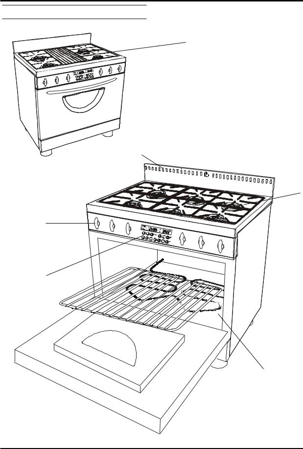
Cooktop Features
A.Burners feature 15,500 BTU (4.4kW) easy clean, sealed style, dual head burners. The outer head is designed for high temperature, heavy duty jobs. The inner head is more suited for low temperature requirements, such as sauces and melting chocolate. Output is adjustable to as low as 450 BTU.
B.Gas burner controls allow for an infinite selection of cooking temperatures. Push and turn style controls are positioned at the front of the cooktop for easy access. All models feature “auto-reignition” Should the flame go out for any reason, the ignitor
automatically begins to spark to reignite the burner.
C.Grill models feature two 7,500 BTU twin burners – for a total of 15,000 BTU. These are adjustable to as low as 1,000 BTU. Front and back grill burners can be seperated independently from each other. Push and turn controls to light each burner. The grill also has the same “auto-reignition” feature as the top burners.
Oven Features
A.Electronic oven control features touch pad controls for accurate cooking settings, regular and convection baking, broiling, self clean functions, minute minder functions, and oven lights.
B.Standard features:
•Standard baking (radiant heat)
•Instant on ribbon broil element
•Timed baking and true convection baking
•Lower Element Convection
•True convection baking, broiling
•Delayed time baking and convection baking
•3 position racking
•4.4 cubic feet of energy efficient baking for 30” models
•5.9 cubic feet of energy efficient baking for 36” models.
•30” models with 3 racks can bake 4 layer cakes, 4 1/2 dozen cookies, 4 dozen muffins
•36” models with 3 racks can bake 6 layer cakes, 6 dozen cookies, 6 dozen muffins
•low maintenance, high temperature, programmable self clean oven
•oven vents out the front of the cresting panel located at the rear of the top.
13
Metro / Legacy Series
Cooking Controls Diagrams
(fig 8)
C
OVEN VENTS THRU THESE SLOTS, LEGACY VENTS FROM
SAME AREA ONLY VENT IS COVERED BY A DECORATIVE
STRIP
A
B
D
E
14
Section 3: Cooking Controls
Control Panel Graphic
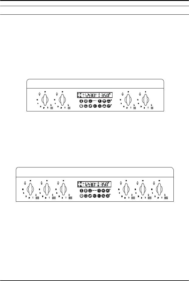
(fig 9)
These illustrations show the control panel layout of each model. Legacy is shown, however, Metro has a similar layout.
4 burner
6 burner and 4 burner with Grill
15
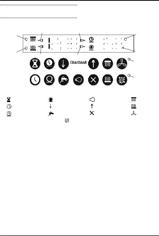
Metro / Legacy Series
Electronic Oven Control
Features
(fig 10)
Convection Broil |
|
Broil Indicator |
|
|
|
|
|
|
Start Time Indicator |
|
|
|
|
|
Element “ON” |
|||
|
|
|
|
|
|
|
|
|
|
|
|
|
|
|
|
|
Indicator |
|
Indicator |
|
|
|
|
|
|
|
|
|
|
|
|
|
|
|
|
|
|
|
|
|
|
|
|
|
|
|
|
|
|
|
|
|
|
|
|
Celsius |
|
|
|
|
|
|
|
|
|
|
|
|
|
|
|
|
|
|
|
|
|
|
|
|
|
|
|
|
|
|
|
|
|
|
|
|
|
|
|
|
|
|
|
|
|
|
|
|
|
|
|
||||||
Convection Bake |
Bake Indicator |
|
|
|
|
|
|
Stop Time Indicator |
|
|
|
|
|
Indicator |
||||
|
|
|
|
|
|
|
|
|
|
|
|
|
||||||
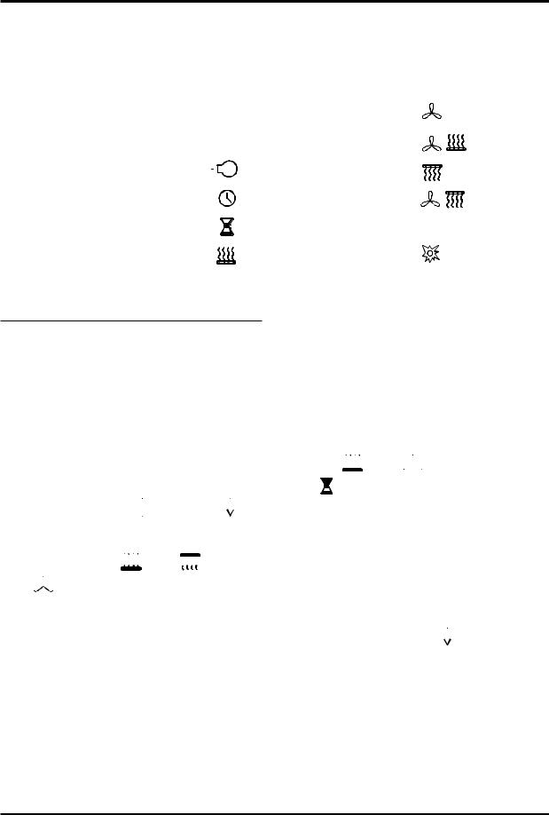
Indicator
Convection Fan
Indicator
Self Clean
Indicator
minute minder |
stop time |
oven light |
broil |
clock |
decrease |
increase |
bake |
cook time |
start |
cancel |
convection |
|
|
self clean |
|
Features:
•Time of day display, selectable 12 hr/24 hr clock mode.
•Count down timer display.
•Fully programmable bake and broil cooking, include cook time, stop time, convection bake and broil, self clean function, etc.
•Temperature setting changeable without canceling any programs.
•Selectable temperature setting in Celsius or Fahrenheit.
•Actual oven temperature is displayed during baking or convection baking mode and will be displayed in 5°F increments until desired tempature is reached.
•Large LED display, 4 digit display time, 3 digit display temperature.
•During running of an oven function, press of function key can recall the setup of the function. After 5 seconds, the display will change back to real temperature and clock display.
•Beep when button is pressed or finish oven programmed function.
•Child safety keyboard lockout.
16
Section 4: Oven and Clock Operation
Oven and Clock Operation
|
|
|
|
|
|
|
|
|
|
|
|
|
|
|
|
|
|
|
|
|
Table Of Contents |
|
|||||||||||
|
|
1. General Information |
7. |
True Convection |
|
|||||||||||
|
|
2. |
Safety Features |
8. |
Convection Bake |
|
||||||||||
|
|
3. |
Oven Light |
|
|
9. |
Broil |
|
|
|
|
|
|
|
||
|
|
|
|
|
|
|
|
|
|
|||||||
|
|
|
|
|
|
|
|
|
|
|||||||
|
|
4. |
Clock Operation |
|
|
|
|
10. Convection Broil |
|
|
|
|||||
|
|
|
|
|
|
|
||||||||||
|
|
5. Minute Minder |
|
|
|
|
11. Sabbath Mode |
|
||||||||
|
|
6. Bake |
|
|
|
|
12. Self Clean |
|
||||||||
|
|
|
|
|
|
|
|
|
|
|
|
|
|
|
|
|
|
|
|
|
|
|
|
|
|
|
|
|
|
|
|
|
|
|
|
|
|
|
|
|
|
|
|
|
|
|
|
|
|
|
1. General Information
•Clock must be set before any other operation of the electronic oven control. No other setting is possible until the clock is set.
•When supplying power to the appliance for the first time or after a power interruption the followingwilloccur:
i.The digital clock will display 88:88
ii.The symbols for 
 increase and
 decrease will flash until the clock is set.
•Oven functions ( 
 bake,
bake, broil,
 convection, etc.) are identified by a symbol on the key pad (fig 11).
•An audible signal will sound each time a function symbol is fully depressed and the symbolwillcommenceflashing.
•After an oven function has started, the correspondingsymbolwillglowcontinually until the function is complete or it has been cancelled.
•Programming of functions can be cancelled at any time to begin again (if more than 20
seconds elapse between consecutive selectionsduringprogramming,thefunctionwillbe cancelledautomatically).
•Time of day is always displayed in hours:minutes.
•The maximum programmable length of time for 
 bake,
bake, convection bake, and
 minute minder functions is 11 hours and
59minutes.
•If set to 295° F or below, display will show SP for 5 seconds.
•After starting any cooking function, the clock will display “11:59” in standard mode.
•When using increase or 

 decrease keys for
setting times,fastscrollingwillbeginafter button is depreased for 5 continuous seconds
17
 Loading...