

Heartland HL-CKNG, HL-CKLP Owner's Manual
PLEASE READ THESE INSTRUCTIONS BEFORE INSTALLING OR USING THIS APPLIANCE.
INSTALLER: LEAVE THESE INSTRUCTIONS WITH THE APPLIANCE.
CUSTOMER: KEEP THESE INSTRUCTIONS FOR FUTURE REFERENCE.
Remember, when replacing a part on this appliance, use only spare parts that you can be assured conform to the safety
and performance specification that we require. DO NOT use reconditioned or copy parts that have not been clearly
authorized by HEARTLAND APPLIANCES INC.
Installation, Servicing,
Users Instructions
& Cooking Guide
HEARTLAND COOKMASTER
OWNERS MANUAL
WARNING: If the information in this manual is not followed exactly, a fire or
explosion may result causing property damage,personal injury or death.
Do not store or use gasoline or other flammable vapors and liquids in the vicinity
of this or any other appliance.
WHAT DO YOU DO IF YOU SMELL GAS
z
Do not try to light any appliance.
z
Do not touch any electrical switch
z
Do not use any phone in your building.
z
Immediately call your gas supplier from a neighbors phone.
Follow the gas suppliers instructions
z
If you can not reach your gas supplier call the fire department.
Installation and service must be performed by a qualified installer, service
agency or the gas supplier.
FOR USE IN USA/CANADA
NATIONALLY RECOGNISED
TESTING LABORATORY
05/06 EINS 514594

SECTION CONTENTS PAGE
INSTALLATION SECTION 4
TECHNICAL DATA 5
SITE REQUIREMENTS INTRODUCTION 6
IMPORTANT 6
GAS SUPPLY 6
LOCATION 7 & 8
VENT CONNECTION 9 & 10
ELECTRICAL 10
INSTALLATION CLEARANCES 11
REQUIREMENTS PRELIMINARY INSTALLATION 11
SITE LOCATION 12
SETTING COMBUSTION 12
INSTALLATION BURNER ACCESS 13
INSTRUCTIONS ELECTRICAL CONNECTION 13
TERMINAL STRIP CONNECTIONS 14
BURNER CONTROL 15
ELECTRICAL CHECK 15
COMBUSTION DISCHARGE SAFETY DEVICE 15
ANCILLARY CONTROLS CHECK 16
INSTRUCT THE USER 16
USERS GUIDE 17
INTRODUCTION 18
SAFETY PRECAUTIONS AND HINTS 19
FEATURES AND ACCESSORIES 20 & 21
SETTING THE TIMER FOR USE 22
USING THE TIMER 23 - 24
THE MINUTE TIMER 25
USING THE AUTOMATIC COOKING FACILITY 26
ROASTING/BAKING OVEN OPERATION 27
COOKING WITH YOUR APPLIANCE 28
COOKING CHART - MAIN OVEN 29
CLEANING AND CARING FOR YOUR AGA 30
SERVICING INSTRUCTIONS 31
INTRODUCTION 32
SERVICE SCHEDULE 32
BURNER REMOVAL PREPARATION 33
BURNER ACCESS 33
BURNER REMOVAL 34
BURNER CHAMBER/ BURNER CHAMBER 35
SERVICING
BURNER SERVICING BURNER HEAD CLEANING 36
ELECTRICAL CONTROLS TERMINAL STRIP CONNECTIONS 37
OVERHEAT SAFETY THERMOSTAT 38
FLUE SAFETY THERMOSTAT 38
BURNER COMBUSTION AIR 39
TEST BURNER ON DRY RUN (NO GAS) 40
2
CONTENTS

SECTION CONTENTS PAGE
REPLACEMENT OF PARTS ELECTRODES 41
(BURNER) CONTROL BOX 41
ELECTRICAL COMPONENT ACCESS 42
TRANSFORMER 42
FUSE 42
TO INSTALL NEW FLUE SAFETY DEVICE 43
TO INSTALL NEW COOKER SAFETY OVERHEAT 44
THERMOSTAT
AND OVEN CONTROL THERMOSTAT
TO INSTALL NEW TIMER 44
RE-ASSEMBLE 44
FAULT-FINDING WIRING DIAGRAM - BURNER ONLY 45
WIRING DIAGRAM - APPLIANCE 46
BURNER DOES NOT START 47
TROUBLE-SHOOTING BURNER 48
TROUBLE-SHOOTING CHART 49
SERVICING OR FAULT 50
3

Installation
Section
4
CAUTION:
THIS UNIT IS HEAVY. PROPER EQUIPMENT AND ADEQUATE
MANPOWER MUST BE USED IN MOVING THE RANGE TO
AVOID DAMAGE TO THE UNIT OR THE FLOOR.
Remember, when replacing a part on this appliance, use only spare parts that you can be
assured conform to the safety and performance specification that we require. Do not use
reconditioned or copy parts that have not been clearly authorized by HEARTLAND
APPLIANCES INC.
THE INSTALLATION OF THIS APPLIANCE MUST CONFORM WITH LOCAL CODES, OR IN
THE ABSENCE OF LOCAL CODES, WITH THE NATIONAL FUEL GAS CODE, ANSI
Z223.1/NFPA 54

DESN 512448
PLEASE NOTE: IT IS ADVISABLE TO
CHECK THE ACTUAL SIZE/WIDTH
OF YOUR APPLIANCE BEFORE
FINALLY FIXING ANY KITCHEN
UNITS, SINCE ENAMELLED CAST
IRON CAN VARY IN SIZE
DIMENSIONS IN MM
5
Gas Inlet 1/2” NPT Unp acked Appliance Weight - 326 Kg (719 lbs)
Electrical Supply 115 V 60 Hz
Natural Gas Propane
Appliance Inlet 10” w.g. 15” w.g.
Pressure (MAX.)
Burner Pressure
- 0.044 w.g. (± 0.012” w.g.) - 0.044 w.g. (± 0.012” w.g.)
(NEGATIVE) (non-adjustable) (non-adjustable)
Max Flue Temp. 445ÞF 450ÞF
CO 0 - 50 ppm 0 - 50 ppm
CO
2
% 8.2% - 9.9% 9.4% - 10.8%
Heat Input 50,000 Btu/hr 50,000 Btu/hr
TECHNICAL DATA

The Aga Cookmaster is a floor standing only cooker, fired by a gas burner. It is suitable for vertical flue outlet only.
The burner fitted to this appliance has been designed and constructed exclusively for use with the Aga
Cookmaster and MUST not be used on any other appliances or any other uses.
Installation Pipes
Pipework from the meter to the appliance must be of adequate size. Do not use pipes of a smaller size than the appliance
gas connection. To avoid undue stress on pipework and burner, adequate support should be used when connecting and
disconnecting union. The complete installation must be tested for soundness and purged in accordance with the
regulations in force.
NOTE: USE SOAPY WATER SOLUTION ON NEW GAS CONNECTIONS TO ENSURE THERE ARE NO GAS LEAKS.
Gas Supply Pipe - U.S. Pipe Threads
NOTE: A GAS CONTROL VALVE MUST BE INSTALLED IN THE GAS PIPELINE EXTERNALLY OF THE RANGE (NOT
SUPPLIED) FOR THE PURPOSE OF TURNING ON OR SHUTTING OFF GAS TO THE APPLIANCE. DO NOT FIT
VALVE BEHIND THE COOKER; IT MUST BE INSTALLED IN AN ACCESSIBLE LOCATION.
The appliance has a 10 mm (1/2”) N.P.T. Male Connection at the front left hand side.
ALL GAS CONTROLS MUST BE U.S. PIPE THREADS.
Maximum Heat Input: 50,000 Btu/h Oven Only
The appliance and its individual shut-off valve must be disconnected from the gas supply piping system during any
pressure testing of that system at test pressure in excess of 1/2 psig (3.5 kPa). The appliance must be isolated from the
gas supply piping system by closing the individual manual shut-off valve during any pressure testing of the gas supply
piping system at test pressures equal to or less than 1/2 psig (3.5 kPa).
Leak testing of the appliance shall be conducted according to the manufacturers instructions.
FLUE SAFETY
DEVICE
For safety purposes, a flue safety device is fitted. This will only operate in adverse flue conditions. If the switch has
operated, it should be pushed in only to reset. If this problem persists, it is necessary to determine and rectify the cause.
If it is found necessary to reset more than once, this may indicate a flue blockage.
INTRODUCTION
IMPORTANT
GAS SUPPLY
Site requirements
6
The appliance is floor mounted and must be installed on a solid floor or base of non-combustible material which is capable
of supporting the total weight.
The location chosen for the appliance must permit the installation and the provision of a satisfactory flue and an adequate
air supply. The location must also provide adequate space for servicing and for air circulation around the appliance. See
“Installation of the Appliance”.
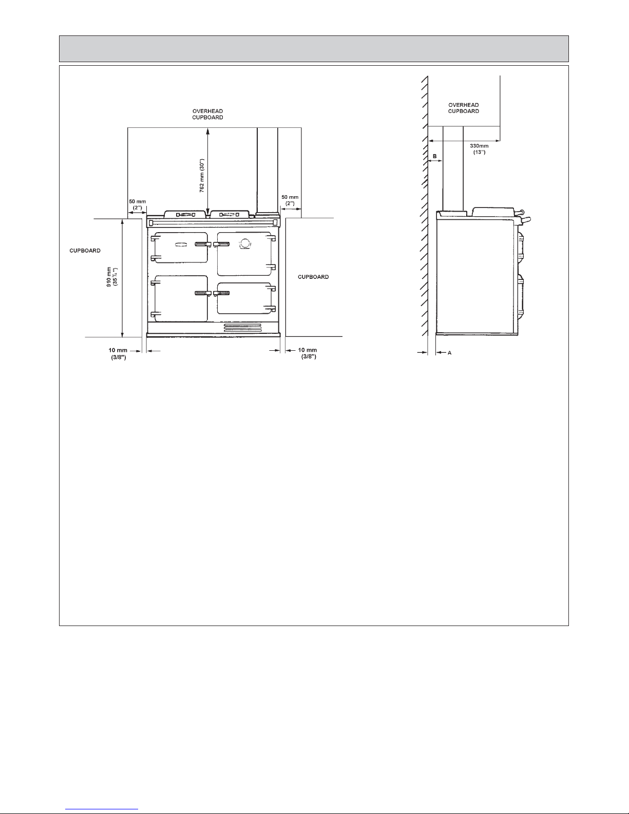
The space in which the appliance is to be fitted must have the following minimum dimensions:
Between wall and LH side of appliance - 10 mm (3/8”)
Between wall and RH side of appliance - 10 mm (3/8”)
SHOULD THE WALL PROJECT BEYOND THE FRONT OF THE APPLIANCE, THEN THE GAP AT THE R.H. SIDE
MUST BE INCREASED TO 50 mm (2”) TO ALLOW REMOVAL OF OVEN SHELVES. (SEE FIG. 1).
Height above the raised hotplate - 762 mm (30”)
Max. depth of cabinets above hotplate - 330 mm (13”)
In addition, adequate clearance must be available at the front of the appliance to enable it to be operated and serviced.
Flue pipes and fittings must not be closer than 57 mm (2
1
/4”) to combustible materials. Any openings in the wall behind
the appliance and in the floor under the appliance shall be sealed.
Spaces around flue pipes passing through walls or floors should be sealed against the passage of smoke and flame.
Where the cooker is to stand in a recess or against a wall which is to be tiled, in no circumstances should the tiles
overlap the cooker top plate.
LOCATION
50 mm
(2”)
10mm (3/8”)
FIG. 1A
WALL PROJECTING BEYOND THE
FRONT OF THE APPLIANCE
Site requirements
7
Site requirements
8
FIG. 1B DESN 512558
INSTALLATION CLEARANCES
REAR DIM ‘A’ COMBUSTIBLE WALL 1” (25mm)
NON-COMBUSTIBLE WALL 0” (0mm)
DIM ‘B’ FLUE PIPE CLEARANCE TO 2
1
/4” (57 mm)
COMBUSTIBLE WALL
NON-COMBUSTIBLE WALL 1” (25 mm)
SIDES BELOW HOTPLATE
3
/8” (10 mm)
SIDES ABOVE HOTPLATE 2” (50 mm)
WALL CABINET OVERHEAD 30” (762 mm)
WALL CABINET OVERHEAD 13” (330 mm)
MAXIMUM DEPTH
WALL CABINET ALONGSIDE 30” (762 mm)
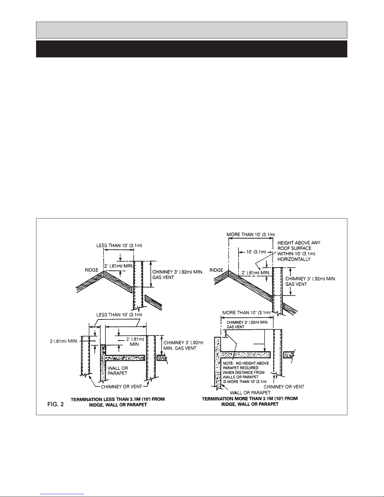
A 125 mm (5”) Type B Gas Vent must be used and fastened by screw to the draft hood flue collar.
U.S.
The gas vent must be connected to a chimney or independently and in accordance with Chapter 26, chimney Gas Vent
and Fireplace Systems of the current issue of Equipment and Volume of the ASHRAE Handbook. The gas vent proximity
to combustion materials must be installed as recommended in ANSI/NFPA 211 and according to manufacturers
instructions. Chimneys and vents shall terminate above the roof level and in accordance with the requirements of the
current issue of ANSI/NFPA 211 (see Fig. 2) and be at least 1.53m (5ft) above the flue collar of the draft hood outlet.
Part 7, Venting of Equipment, outlined in the current National Gas Code ANSI Z223, gives detailed guidelines on all these
aspects.
Canada:
The gas vent must be connected to a chimney or independently and in accordance with the CAN/CGA - B149 Installation
Codes.
The air gap between vent and combustible materials must be given for the following types of vent:
(i) Type B Vent - 25mm (1in) minimum
(ii) Single wall vent connector - 150mm (6in) minimum
Listed connectors passing through the combustible walls and partitions must be guarded by a ventilated metal thimble not
less than 200mm (8in) diameter.
VENT CONNECTION
Site requirements
9

Chimneys and vents shall terminate above roof level and in accordance with the requirement of the current issue of the
CAN/CGA - B149 Installation Code (Code W) (see Fig. 2) and be at least 1.53m (5ft) above the flue collar of the draft outlet.
1. If suitable, lined brick chimney is used it must be swept before connection and not less than 150mm (6in) internal
diameter.
2. The top of the chimney should be fitted with an approved terminal.
3. The flue route to the chimney should be as direct as possible. Resistance in the form of directional change should be
kept to a minimum. Right angle bends and horizontal runs should be avoided.
4. The chimney terminal should terminate at the highest possible point, preferably in a freely exposed position.
Termination at the roofs eaves is unacceptable.
5. The Aga Distributor or local gas company should be advised if there is any doubt as to the suitability of the flue.
6. Approved factory made chimneys are acceptable with the appliance and should not be less than 10mm (4in) internal
diameter.
7. In the event of an extractor fan being fitted in the vicinity of the range, compensatory ventilation will be required to
satisfy the demands of the fan without influencing combustion efficiency or chimney flue condition.
110/120V 60 Hz 10 AMP FLEXIBLE CORD AND PLUG PARALLEL TYPE. When installed, the appliance must be
electrically grounded in accordance with local codes or, in the absence of codes, with National Electrical Codes
ANSI/NFPA 70.
An electrical socket must be provided within 6 feet of the LH side of the appliance and easily accessible to the user to
disconnect. Do not position socket above the appliance.
Take special care when cutting holes in wall or floor. Electrical wires may be behind the wall or floor covering and could
cause an electrical shock if you touch them.
Locate any electrical circuits that could be affected by the installation of this product and disconnect power circuit
WARNING
Electrical Grounding Instructions
This appliance is equipped with a (three-prong) grounding plug for your protection against a shock hazard and should
be plugged directly into a proper receptacle. Do not cut or remove the grounding prong from this plug.
Do not have a fuse in the neutral or grounding circuit. A fuse in the neutral or grounding circuit could result in electrical
shock.
Do not use an extension lead with this appliance.
Check with a qualified electrician if you are not sure the appliance is properly grounded.
Failure to follow these instructions could result in death or serious injury.
VENT CONNECTION (continued)
ELECTRICAL
Site requirements
10
The appliance is floor mounted. The space in which the
appliance is to be fitted must have the following minimum
dimensions.
Between wall and LH side of appliance - 10mm (1/2”)
Between wall and RH side of appliance - 10mm (1/2”)
SHOULD THE WALL PROJECT BEYOND THE FRONT
OF THE APPLIANCE, THEN THE GAP AT THE R.H.
SIDE MUST BE INCREASED TO 50mm (2”) TO ALLOW
REMOV ALOF OVEN SHEL VES. SEE PAGE 4 - FIG. 1A.
Above the raised insulating cover handle - 60mm (3”)
In addition, adequate clearance must be available at the
front of the appliance to enable it to be operated and
serviced.
The appliance is delivered in a fully assembled condition
with the exception of the following items which are
supplied separately packed and require assembly:
The appliance rear distance bracket.
The cooker handrail.
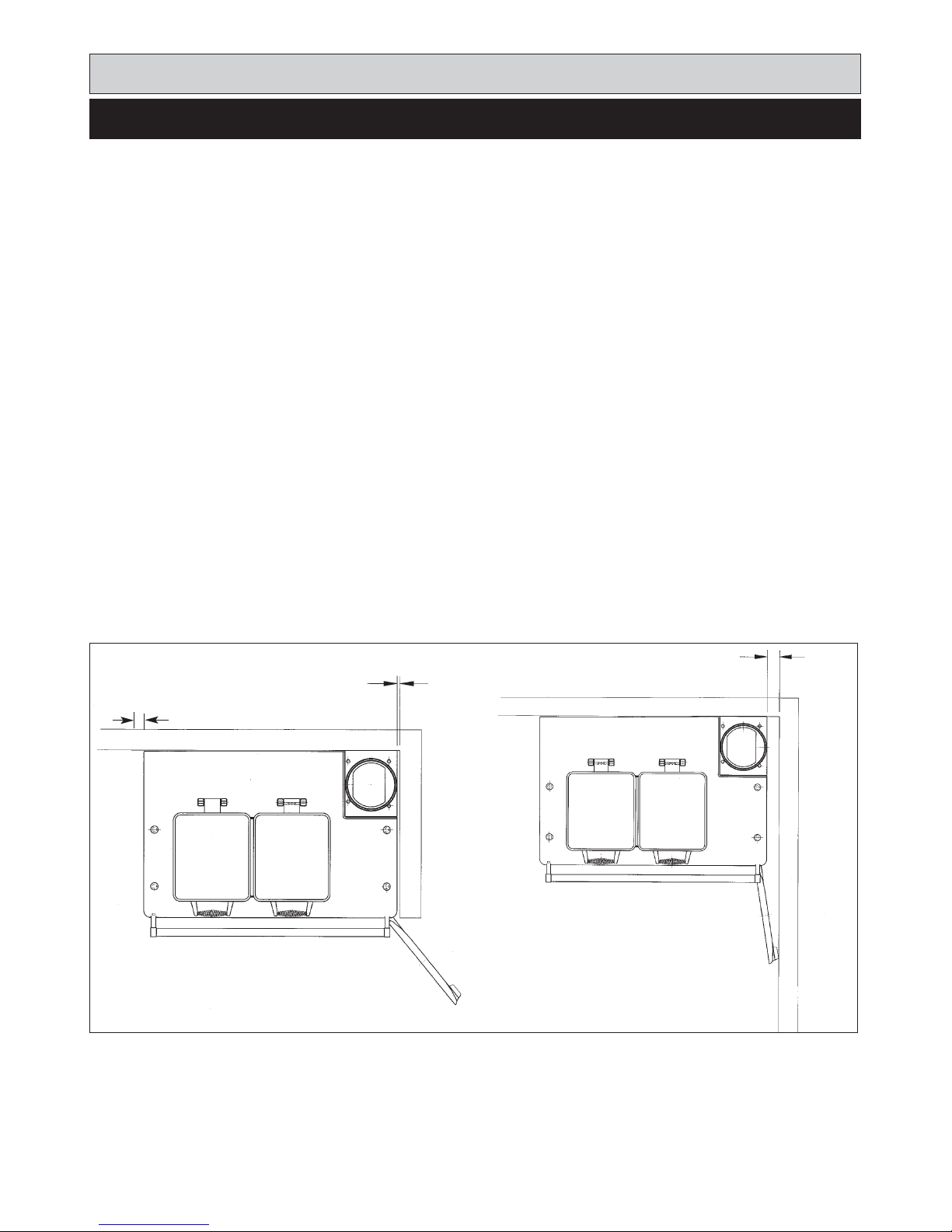
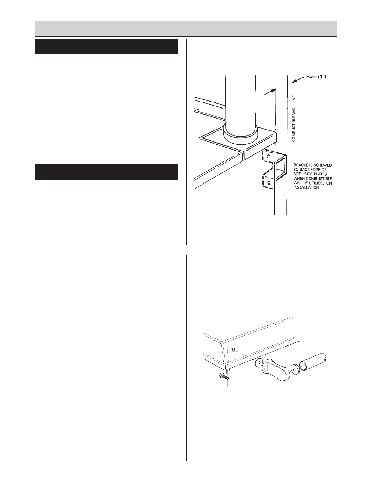
Appliance rear distance bracket: if the rear wall is of
combustible material, there must be an air gap of 25mm
(1”) between the wall and the rear of the cooker. Fit the
rear distance brackets as shown in Fig. 3. Whenever
possible it is recommended that the skirting board is
removed for the width of the appliance to enable the rear
edge of the appliance top plate to make contact with the
vertical wall and avoid a rear gap. (Combustible wall
excepted).
Where the cooker is to stand in a recess or against a wall
which is to be tiled, IN NO CIRCUMSTANCES SHOULD
THE TILES OVERLAP THE TOP PLATE.
The handrail brackets are held on the front edges of the
cooker top-plate casting. Remove the travel nuts and
replace with the handrail brackets ensuring the fiber
protecting washers are in position. Insert the handrail with
fitted end caps into the brackets, positioning them
correctly, and tighten the locating bolts (Fig. 4).
Installation requirements
CLEARANCES
PRELIMINARY INSTALLATION
FIG. 3
DESN 510226
FIG. 4
DESN 510454 ‘A’
11

Installation requirements
SITE LOCATION SETTING COMBUSTION
1. Check that the hearth is level, then remove the
appliance from its transit wooden pallet, and position
it with its back against the wall and in its intended
position for flue connection.
2. Locate and fit flue pipe into socket of flue pipe
adaptor, seal joint with rope and fire cement.
3. Connect and terminate the flue system in accordance
with the regulations in force.
Connect the relevant services to the appliance:
1. Gas
2. Electric
3. Flue Pipe
Because this appliance uses a pre-mix burner, no setting
up of combustion is required; the burner automatically
controls the air to gas rate ratio.
12
- SEE FIG. 5
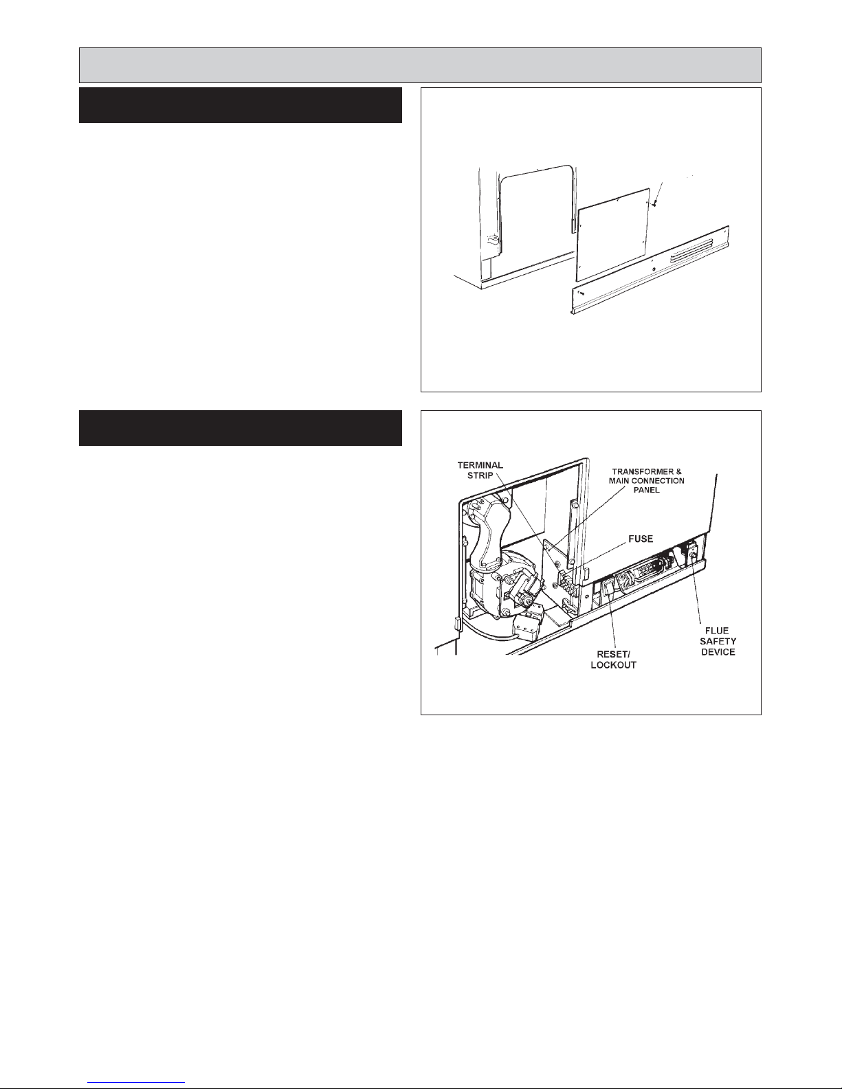
1. Open the burner access door.
2. Remove (5) inner panel securing screws and remove
panel.
3 Remove the (3) plinth securing screws and remove
plinth.
- SEE FIG. 6
This appliance comes with a three-prong plug which
should be connected to a proper receptacle. See page 10
(Electrical). This is fitted internally to the terminal strip
shown in Fig. 6 and Fig. 7.
Installation Instructions
BURNER ACCESS
ELECTRICAL CONNECTION
DESN 511424
DESN 512568
FIG. 6
FIG. 5
13
Installation Instructions
FIG. 7
14
TERMINAL STRIP CONNECTIONS
Installation Instructions
When the thermostat is calling for heat, 230V is supplied
to terminals 10 and 11 on the control box and tab 1 and 2
on the fan, energizing the fan.
There will then be a short delay while the control box
checks that the fan is running and pre-purges. Providing
there is gas to the burner, combustion should be
established after approximately 30 seconds.
On first firing after installation or servicing, the burner may
go to lock out, until all the air has been purged out of the
burner. Wait at least 10 seconds before pressing the reset
button. (See Fig. 8).
Check gas cock is in the on position.
Check inlet gas pressure at test point.
Check to ensure electrical safety is carried out by a
competent person.
For safety purposes, a combustion discharge safety
device is fitted. This will only operate under adverse flue
conditions. If the switch has been operated, it should be
pushed in to reset. If this problem persists, contact your
local engineer to determine and rectify the cause. It is
important not to reset more than once as this may indicate
a flue blockage.
WARNING: The combustion discharge safety device
must not be interfered with or rendered inoperative, as
this could interfere with the safe operation of the
appliance and invalidate the appliance warranty.
BURNER CONTROL
ELECTRICAL CHECK
COMBUSTION DISCHARGE SAFETY
DEVICE
FIG. 8
DESN 512346
RESET BUTTON
GAS SUPPLY
TEST POINT
15

Before leaving the site, check that the operation of cooker
timer and thermostat are capable of controlling the burner
correctly. Check the operation of burner control box.
1. Advise the User that, for continued efficient and safe
operation of the appliance, it is important that adequate
servicing is carried out annually.
2. Hand the Operating Instructions to the User and
demonstrate the correct operation of the appliance and
system controls.
3. Leave the Installation and Servicing Instructions with
the User.
Installation Instructions
ANCILLARY CONTROLS CHECK INSTRUCT THE USER
16
 Loading...