

Heartland DT10 Hardware Manual
Ver.1.21
Hardware Manual
361 Fukui-cho, Ashikaga city, Tochigi prefecture 326-0338 Japan
Tel:+81-284-22-8791 / Fax:+81-284-22-8792
URL: heartlanddata.com

DT10 Hardware Manual
Copyright © 2012 -2014 Heartland. Data Inc.
About this manual
・ This manual explains the hardware specification and how to operate the DT10.
・ This program and manual are protected by Copyright Law, and no reproduction, reprinting or modification
whatsoever is permitted.
・ The content and specification of this product are subject to change without prior notice.
・ Please acknowledge that our company cannot assume any responsibilities for the result of use.
・ Microsoft, Windows, and the Windows logo are registered trademarks in the United States and other countries of
United States Microsoft Corporation.
・ All other company names, logos, and product names, etc. specified are the trademarks or registered trademarks of
each respective company.
DT10 Hardware Manual
Copyright © 2012 -2014 Heartland. Data Inc.
Product precautions
・ To use this product safely, please read this manual before using.
Caution on installation
Caution
Install DynamicTracer in a horizontal and stable place.
Install DynamicTracer in a well-ventilated place.
Where the risk of static electricity is high, use the antistatic mat to protect DynamicTracer.
Install DynamicTracer in a wide and flat space. The bottom rubber must be in contact with the
ground.
Never install DynamicTracer near any volatile substances or fire.
Never install / store in the following places:
・ An unstable place
・ A place within children’s reach
・ A place exposed to any other mechanical vibration.
Never install in any of the following places to protect DynamicTracer against fire, electric shock,
malfunction, and other troubles:
・ A humid/dusty place
・ A wet place
・ A place exposed to direct sunlight
・ A place subject to considerable fluctuations in temperature and humidity
・ A place near HVAC equipment.
DT10 Hardware Manual
Copyright © 2012 -2014 Heartland. Data Inc.
Cautions regarding power
Caution
Never connect/disconnect the power plug while hands are wet to prevent the risk of electric
shock.
Never use an unlabeled power plug (other than 100 - 240V AC) and never use octopus tentacle
power wire.
Never use a broken AC wire to prevent electric shock and fire.
Obey the following rules when using an AC wire:
・ Never modify the AC wire.
・ Never expose the AC wire to strain.
・ Never bend, twist and pull hard.
・ Never place near heat equipment.
Handle AC plugs carefully to prevent fire:
・ Never plug in a dusty AC plug.
・ Plug in the AC plug firmly.
Unplug AC plug while holding it firmly.
Never unplug by pulling the AC wire to prevent the risk of fire and electric shock.
Clean the AC plug regularly.
If not using DynamicTracer for an extended period, unplug the AC plug for safety.
Cautions when using
Caution
Never use if you notice any strange condition (smoke, strange smell, strange sound, etc...).
Stop using DynamicTracer if is contaminated with water or any foreign body.
Do not decompose/custom DynamicTracer.
Never place any heavy object on DynamicTracer.
Connect DynamicTracer to a PC by a cable connector ensuring the cable is in the correct
direction.
When moving DynamicTracer, switch the power off, unplug the AC cable for safety and ensure all
cables/connectors are disconnected.

DT10 Hardware Manual
Copyright © 2012 -2014 Heartland. Data Inc.
Contents
1. HARDWARE SPEC. OF DYNAMICTRACER ............................................................................. - 1 -
1.1. APPEARANCE (FRONT) ............................................................................................................... - 1 -
1.2. APPEARANCE (REAR) ................................................................................................................. - 1 -
1.3. CONNECTION IMAGE ................................................................................................................... - 1 -
2. HARDWARE SPEC. OF CONNECT BOX A............................................................................... - 2 -
2.1. APPEARANCE (TOP) ................................................................................................................... - 2 -
2.2. SUPPORTED CONNECTION METHODS .......................................................................................... - 2 -
2.3. ELECTRIC SPEC. ........................................................................................................................ - 2 -
2.4. ASYNC BUS CONNECTION ........................................................................................................... - 3 -
2.4.1. Timing chart
...................................................................................................................... - 3 -
2.4.2. FPC cable connection spec.
............................................................................................. - 4 -
2.5. GPIO CONNECTION 4BIT / 2BIT ................................................................................................... - 5 -
2.5.1. Timing chart
...................................................................................................................... - 5 -
2.5.2. GPIO connection spec.
.................................................................................................... - 6 -
2.6. SPI CONNECTION ....................................................................................................................... - 8 -
2.6.1. Timing chart
...................................................................................................................... - 8 -
2.6.2. SPI connection spec.
........................................................................................................ - 9 -
3. HARDWARE SPEC. OF CONNECT BOX B ............................................................................ - 11 -
3.1. APPEARANCE (FRONT) ............................................................................................................. - 11 -
3.2. SUPPORTED CONNECTION METHODS ........................................................................................ - 11 -
3.3. COMMUNICATION SPEC............................................................................................................. - 11 -
4. HARDWARE SPEC. OF CONNECT BOX C ............................................................................ - 12 -
4.1. APPEARANCE (FRONT) ............................................................................................................. - 12 -
4.2. SUPPORTED CONNECTION METHODS ........................................................................................ - 12 -
4.3. ELECTRIC SPEC. ...................................................................................................................... - 12 -
4.4. ASYNC BUS CONNECTION ......................................................................................................... - 14 -
4.4.1. Async bus connection spec.
........................................................................................... - 14 -
4.4.2. Timing chart
.................................................................................................................... - 14 -
4.5. GPIO CONNECTION 4BIT / 2BIT ................................................................................................. - 15 -
4.5.1. Timing chart
.................................................................................................................... - 15 -
4.5.2. GPIO connection spec.
.................................................................................................. - 15 -
4.5.3. Level Shifter switch spec.
............................................................................................... - 16 -

DT10 Hardware Manual
Copyright © 2012 -2014 Heartland. Data Inc.
4.6. SPI CONNECTION ..................................................................................................................... - 17 -
4.6.1. Timing chart
.................................................................................................................... - 17 -
4.6.2. SPI connection spec.
...................................................................................................... - 17 -
4.6.3. Level Shifter switch spec.
............................................................................................... - 18 -
4.7. SD I/F CONNECTION ................................................................................................................ - 19 -
4.7.1. Connection spec. of SD I/F
............................................................................................ - 19 -
4.7.2. Timing chart
.................................................................................................................... - 19 -
5. HARDWARE SPEC. OF ANALOG BOX .................................................................................. - 20 -
5.1. APPEARANCE (TOP) ................................................................................................................. - 20 -
5.2. HOW TO CONNECT ................................................................................................................... - 20 -
5.3. LOGIC SIGNAL INPUT SPEC. ....................................................................................................... - 21 -
5.4. ANALOG SIGNAL INPUT SPEC. ................................................................................................... - 22 -
6. HARDWARE SPEC. OF CAN CONNECTION .......................................................................... - 23 -
6.1. APPEARANCE ........................................................................................................................... - 23 -
6.2. COMMUNICATION SPEC............................................................................................................. - 23 -
6.3. HOW TO CONNECT ................................................................................................................... - 23 -
7. CHANGE HISTORY ................................................................................................................. - 24 -
DT10 Hardware Manual
Copyright © 2012-2014 Heartland. Data Inc.
- 1 -
1. Hardware spec. of DynamicTracer
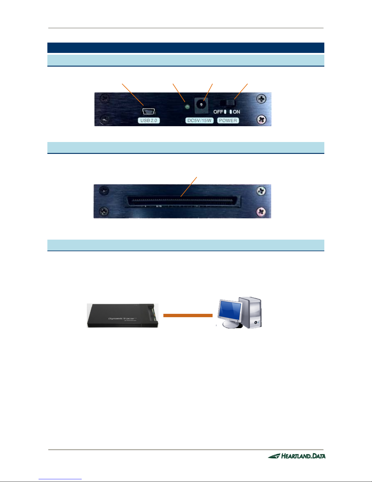
1.1. Appearance (front)
1.2. Appearance (rear)
1.3. Connection image
Use the attached USB cable to connect DynamicTracer to the PC being used.
The PC’s USB port must support USB2.0.
Mini USB connector
Power LED
AC connector
Power Switch
Connect Box / Analog Box connector
USB2.0
PC
DynamicTracer
DT10 Hardware Manual
Copyright © 2012-2014 Heartland. Data Inc.
- 2 -
2. Hardware spec. of Connect Box A
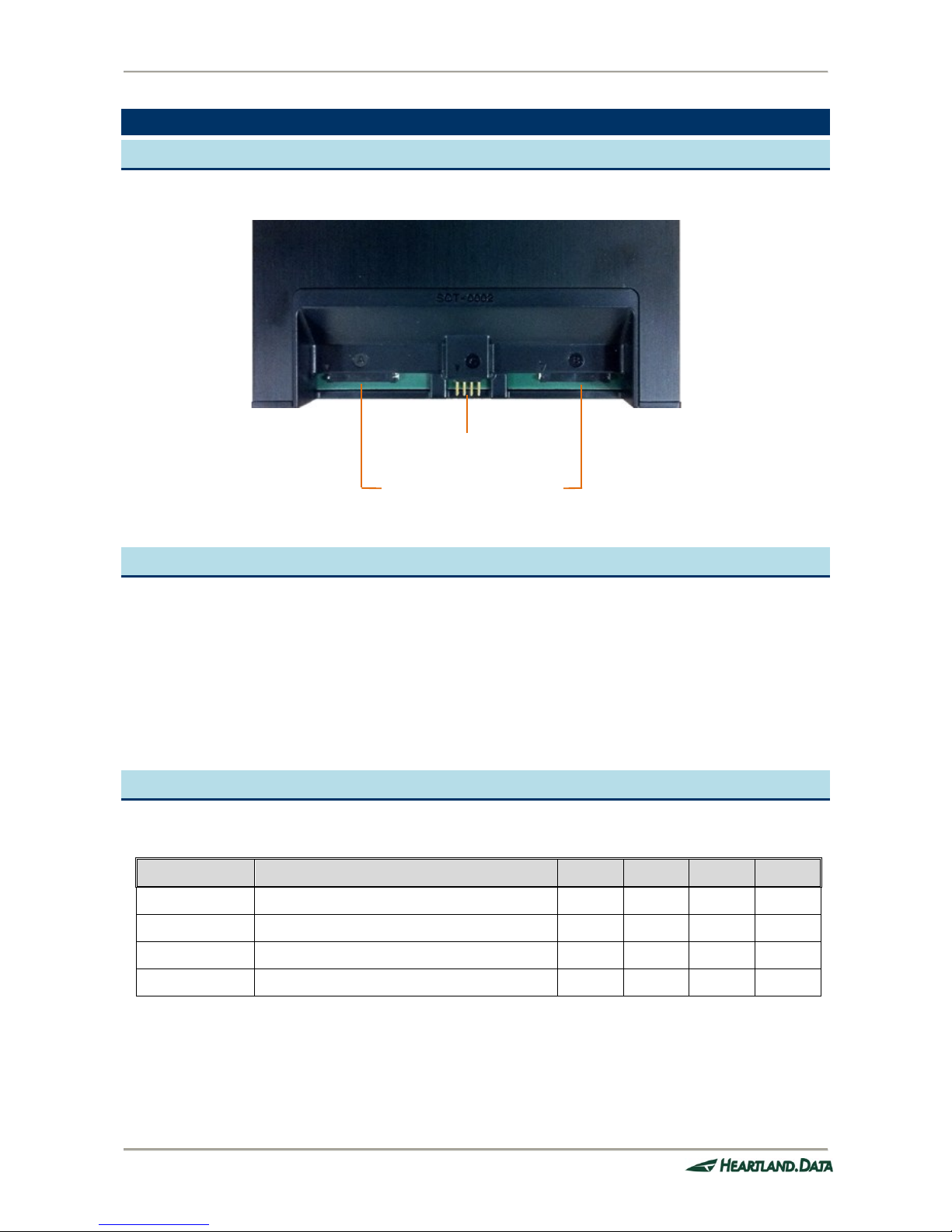
2.1. Appearance (top)
2.2. Supported connection methods
Connect Box A supports the following connection methods:
Async Bus : Async bus connection.
GPIO : GPIO (4bit / 2bit) bus output method connection.
SPI : SPI output bus method connection.
SD I/F : Connection that supports the SD interface.
2.3. Electric spec.
Recommended operating condition (Connect Box A)
Name
Description
MIN
TYP
MAX
UNIT
VIH
High-level input voltage
2.37 V VIL
Low-level input voltage
0.99
V
VI
Input voltage
0 5.5
V
RIN
Input resistance
100 KΩ
・ VIH/VIL/VI/RIN is the spec. of the probe and FPC cable.
8pin probe connection terminal
FPC cable connection terminal
DT10 Hardware Manual
Copyright © 2012-2014 Heartland. Data Inc.
- 3 -
2.4. Async bus connection
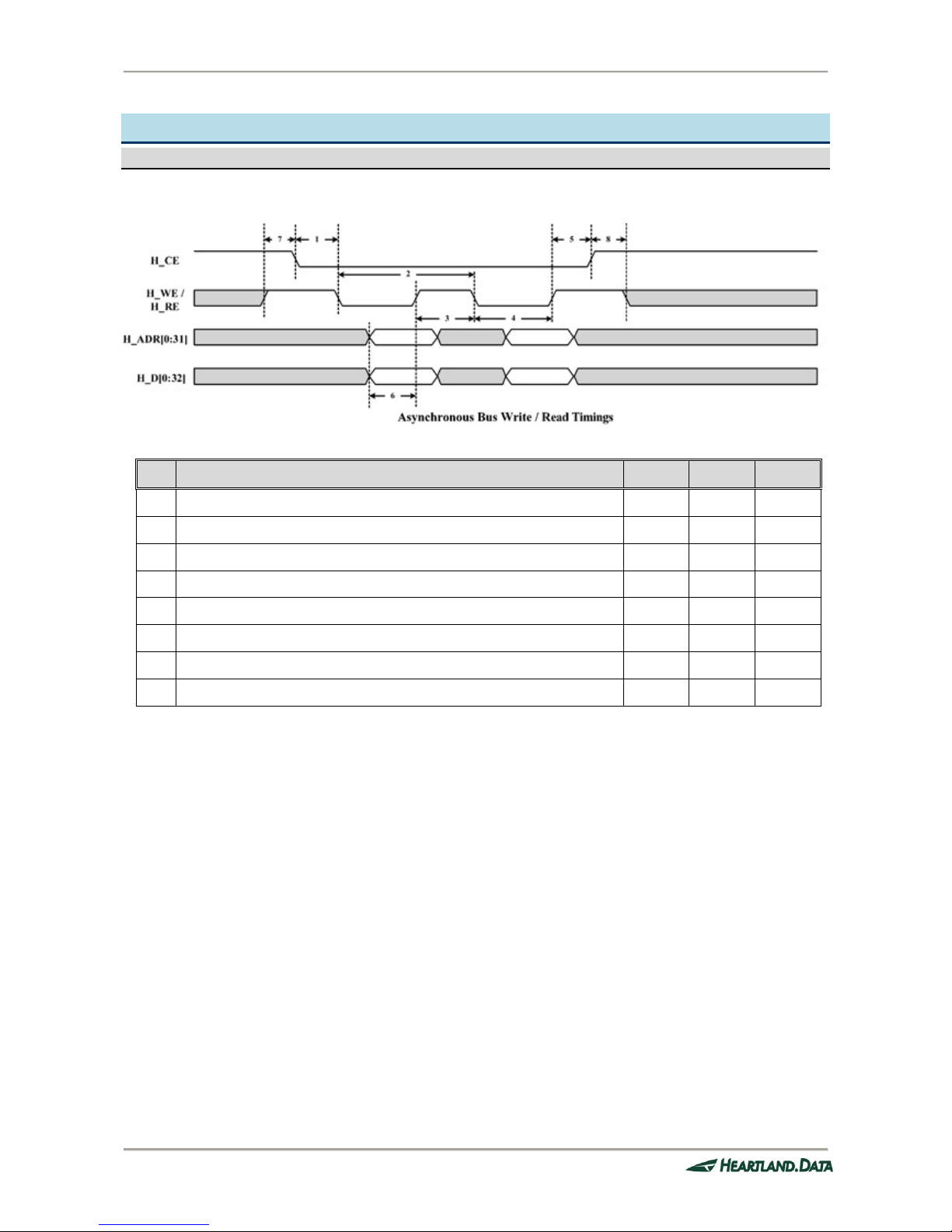
2.4.1. Timing chart
Async bus Write/Read timing
No.
Description
MIN.
MAX.
UNIT
1
H_CE setup time
0 ns
2
H_WE/H_RE period
54 ns
3
H_WE/H_RE high-level period
27 ns
4
Data/Address setup time
27 ns
5
H_CE hold time
0 ns
6
Data/Address latch timing
10 ns
7
Waiting time from other CE access to H_CE active
0 ns
8
Waiting time from H_CE high-edge to CE access
0 ns
DT10 Hardware Manual
Copyright © 2012-2014 Heartland. Data Inc.
- 4 -
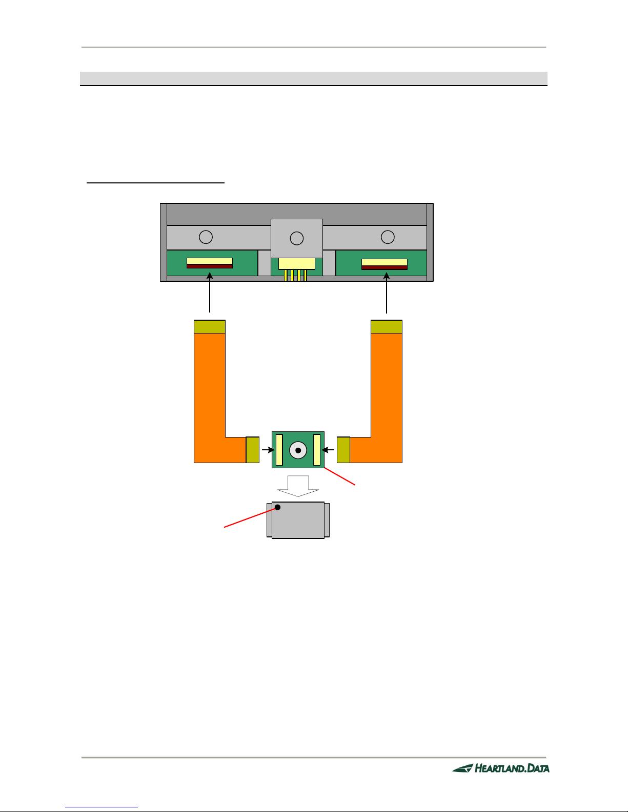
2.4.2. FPC cable connection spec.
When using an Async bus connection, connect the FPC cable to Connect Box A.
When connecting an FPC cable to the target, an attachment is needed. The attachment mounting manual specifies how
to attach the attachment.
FPCケーブル接続図
▼
C
A B
▼ ▼
SCT-0002先端図
※8ピンプローブと、
FPCケーブルは、
同時に挿入しないで
下さい。
NOR Flashの1ピン位置が
本体側になるようにアタッ
チメントを取りつけます。
NOR Flashの端子とFPCケーブルを接続するために
は、NOR FlashのPIN数に合ったアタッチメントを取り
つける必要があります。
下記タイプがありますのでターゲット環境に合わせ
てお選びください。
TSOP-48 PIN
TSOP-56 PIN Intel系
TSOP-56 PIN AMD系
FPC cable connection image
SCT-0002 head image
* Never insert the 8PIN
cable and FPC cable at
the same time.
Fit the attachment.
Here, 1 pin is shown.
When attaching, the number of pins on the
NOR Flash must match the connect pin of
the NOR Flash and FPC cable. The following
types are available - please use according to
the target:
TSOP-48PIN
TSOP-56PIN Intel
TSOP-56PIN AMD
 Loading...