


Hearth and Home Technologies VRT-BZ-N-CE, VRT-BZ-P-CE, VRT-GY-N-CE, VRTIKL-CE, VRT-GY-P-CE User Manual
...VRTIKL-CE
FREESTANDING STOVE
MODEL:
VRT-BZ-N-CE VRT-GY-P-CE VRT-GR-N-CE VRT-BZ-B-CE VRT-GY-N-CE VRT-GR-B-CE VRT-BZ-P-CE VRT-GY-B-CE VRT-GR-P-CE
Installer’s Guide
Installation and Operation
0063-06
CAUTION
DO NOT DISCARD THIS MANUAL
• Important operating |
• Read, understand and follow |
• Leave this manual with |
and maintenance |
these instructions for safe |
party responsible for |
instructions included. |
installation and operation. |
use and operation. |
DO DISCARDNOT
 WARNING: If the information in these instructions is not followed exactly, a fire or explosion may result causing property damage, personal injury, or death.
•Do not store or use gasoline or other flammable vapors and liquids in the vicinity of this or any other gas stove.
•What to do if you smell gas
-Do not try to light any gas stove. Do not touch any electrical switch. Do not use any phone in your building.
-Immediately call your gas supplier from a neighbor’s phone. Follow the gas supplier’s instructions.
-If you cannot reach your gas supplier, call the fire department.
•Installation and service must be performed by a qualified installer, service agency, or the gas supplier.
 WARNING
HOT SURFACES!
Glass and other surfaces are hot during operation AND cool down.
Hot glass will cause burns.
• DO NOT touch glass until it is cooled
•NEVER allow children to touch glass
•Keep children away
•CAREFULLY SUPERVISE children in same room as fireplace.
•Alert children and adults to hazards of high temperatures.
High temperatures may ignite clothing or other flammable materials.
•Keep clothing, furniture, draperies and other flammable materials away.
This appliance has been supplied with an integral barrier to prevent direct contact with the fixed glass panel. DO NOT operate the appliance with the barrier removed.
Contact your dealer if the barrier is not present or help is needed to properly install one.
Installation and service of this gas stove should be performed by qualified personnel.
These instructions are valid for the following countries: GB, IE
Î
Heat & Glo • VRTIKL-CE • 7031-292 Rev E • 12/07 |
1 |
Read this manual before installing or operating this gas stove. Please retain this owner's manual for future reference.
Congratulations
Congratulations on selecting a Heat & Glo gas stove - an elegant and clean alternative to wood burning stoves. The Heat & Glo gas stove you have selected is designed to provide the utmost in safety, reliability, and efficiency.
As the owner of a new gas stove, you'll want to read and carefully follow all of the instructions contained in this Owner's Manual. Pay special attention to all Cautions and Warnings.
This Owner's Manual should be retained for future reference. We suggest that you keep it with your other important documents and product manuals.
The information contained in this Owner's Manual, unless noted otherwise, applies to all models and gas control systems.
Your new Heat & Glo gas stove will give you years of durable use and trouble-free enjoyment. Welcome to the Heat & Glo family of gas stove products!
SAMPLE OF RATINGS LABEL
LOCATION: IN CONTROL AREA, INSIDE LOWER ACCESS DOOR
Test Lab &
Report No.
Manufactured
Date
SERIAL NO.
|
Heat & Glo, a brand of Hearth & Home Technologies, Inc. |
|
||||
|
20802 Kensington Boulevard |
|
|
|
|
|
|
Lakeville, MN 55044, USA |
|
|
|
|
|
|
w w.heatnglo.com |
|
|
|
MADE |
|
|
|
|
|
|
|
|
|
Model: ION-CE |
|
|
|
IN USA |
|
0087 |
|
|
|
|
||
|
|
|
|
|
|
|
Gas Type |
G20 |
G20 |
|
G20 |
G2 5 |
|
Destination |
ES, GB, IE, PT, NO |
DE, LU |
|
FR |
|
N L |
CAT |
I2 H |
I 2E |
|
I2E |
R |
I2L |
Qn |
7.6 |
7.6 |
|
7.6 |
6.2 |
|
P n |
20 mbar |
20 mbar |
20/25 mbar |
25 mbar |
||
Pmax |
8.7 mbar |
8.7 mbar |
|
8.7 mbar |
8.7 mbar |
|
SAMPLE |
||||||
Injector |
#39DMS |
#39DMS |
|
#39DMS |
#39DMS |
|
|
Not for use with solid fuel. |
|
|
|
|
|
|
F |
|
|
|
|
G Alcove |
|
B |
C |
H |
|
A |
A |
|
E |
D |
|
|
|
|
A |
A |
|
|
|
|
|
|
C |
|
|
|
|
|
|
inimum Clearances to Combustibles |
|
||||
|
- Side of appliance top to side wall.............. |
|
|
15.2 cm |
||
B |
- Rear of appliance to back wall ................... |
|
|
7.6 cm |
||
C |
- Corner of appliance top to side wall |
.......... |
12.7 cm |
|||
D |
- Minimum Alcove Height........................... |
|
|
137.2 cm |
||
E |
- Maximum Alcove Depth ............................ |
|
|
91.4 cm |
||
F |
- Minimum Alcove Width |
............................. |
|
|
78.1 cm |
|
G - Top of appliance to alcove ...........ceiling |
|
|
33.7 cm |
|||
H |
- Mantle Clearance from .......appliance top |
26.7 cm |
||||
DO NOT REMOVE OR COVER THIS LABEL. |
||||||
This appliance must be installed in accordance with the codes enforced, and used only in |
||||||
ventilated space. Consult instructions before installation and use of |
this appliance. |
|||||
Manufactured by:
Date of Manufacture:
Serial No.
Model Name
2 |
Heat & Glo • VRTIKL-CE • 7031-292 Rev E • 12/07 |
- TABLE OF CONTENTS -
Section 1: Listing and Code Approvals |
|
|
A. Gas Stove Certifications ........................... |
4 |
|
B. Glass Specifications ................................. |
4 |
|
C. Non-Combustible Materials ...................... |
4 |
|
D. Combustible Materials .............................. |
4 |
|
Section 2: |
Getting Started |
|
A. Design & Installation Considerations ........ |
5 |
|
B. Inspect Gas Stove & Components............ |
5 |
|
Section 3: Gas Stove Location & Clearances |
|
|
A. Selecting Gas Stove Location................... |
6 |
|
B. Clearances to Combustibles..................... |
6 |
|
C. Optional Stone Surround Installed............ |
7 |
|
Section 4: |
Termination Locations |
|
A. Flue Termination Clearances.................... |
8 |
|
Section 5: |
Flue Information |
|
A. Flueing Components............................... |
10 |
|
B. Use of Elbows......................................... |
10 |
|
C. Measuring Standards.............................. |
10 |
|
D. Flueing Diagrams.................................... |
11 |
|
E. Horizontal Termination............................ |
16 |
|
F. Slim Line Wall Thimble .......................... |
17 |
|
G. Vertical Termination................................ |
19 |
|
H. Vertical Flue Restrictor ........................... |
21 |
|
Section 6: |
Gas Information |
|
A. Gas Pressure Requirements .................. |
22 |
|
B. Gas Connection.. .................................... 22 |
||
Section 7: |
Electrical Information |
|
A. Ignition System Wiring ............................ |
23 |
|
Section 8: Gas Stove Setup |
|
||
A. Remove Shipping Materials.................... |
24 |
||
B. Unbolting Gas Stove from the Pallet....... |
24 |
||
C. Leveling and Lagging Down the |
|
||
|
Gas Stove ............................................... |
24 |
|
D. Accessories ............................................ |
25 |
||
E. Top to Rear Vent Conversion ................. |
25 |
||
F. |
Installing the Baffle ................................. |
26 |
|
G. Positioning the Logs ............................... |
27 |
||
H. Mineral Wool........................................... |
27 |
||
I. Front Door Glass Assembly.................... |
28 |
||
J. Inner Glass Door Replacement .............. |
28 |
||
Section 9: |
Operating Instructions |
|
|
A. Before Lighting Gas Stove...................... |
29 |
||
B. Lighting Gas Stove ................................. |
30 |
||
C. After Gas Stove is Lit .............................. |
31 |
||
D. Frequently Asked Questions................... |
31 |
||
Section 10: Maintaining & Servicing Gas Stove |
|||
A. Maintenance Tasks.......................................... |
33 |
||
B. Service and Maintenance Log ......................... |
34 |
||
Section 11: |
Troubleshooting............................ |
35 |
|
Section 12: |
Reference Materials |
|
|
A. Gas Stove Dimension Diagram .............. |
35 |
||
B. Gas Stove Dimension with Stone |
|
||
|
Surround Diagram .................................. |
36 |
|
C. Flue Components Diagram..................... |
37 |
||
D. Flue Components List............................. |
38 |
||
E. |
Service Parts List.................................... |
40 |
|
F. |
Warranty Policy....................................... |
43 |
|
G. |
Contact Information ................................ |
44 |
|
Î = Contains updated information.
Heat & Glo • VRTIKL-CE • 7031-292 Rev E • 12/07 |
3 |
1Listing and Code Approvals
A. Appliance Certification
MODEL |
VRTIKL-CE |
LABORATORY |
Gastec Certification B.V. |
TYPE |
Gas Stove |
STANDARD |
EN 613:2001 |
DIRECTIVE |
CAD90/396/EEC |
These instructions are only valid if the following country symbol is on the gas stove. If this symbol is not present on the gas stove, it is necessary to refer to the technical instructions which will provide the necessary information concerning the modification of the gas stove to the conditions of use for the country.
C. Non-Combustible Materials
Materials that are reported as passing ASTM E 136, Standard Test Method for Behavior of Materials in a Vertical Tube Furnace at 750°C, shall be considered non-combustible materials.
D. Combustible Materials
Materials made of or surfaced with wood, compressed paper, plant fibers, plastics, or other materials that can ignite and burn, whether flame proofed or not, or whether plastered or unplastered shall be considered combustible materials.
B. Glass Specifications
This gas stove is equipped with 5mm ceramic glass behind the curved glass. Replace glass only with 5mm ceramic glass. Please contact your dealer for replacement glass.
 WARNING
Do NOT use this gas stove if any part has been under water. Immediately call a qualified service technician to inspect the gas stove and to replace any part of the control system and any gas control which has been under water.
4 |
Heat & Glo • VRTIKL-CE • 7031-292 Rev E • 12/07 |
2 Getting Started
A. Design & Installation Considerations
Heat & Glo direct flue gas stoves are designed to operate with all combustion air siphoned from outside of the building and all exhaust gases expelled to the outside. No additional air source is required.
CAUTION
Check building codes prior to installation.
•Installation MUST comply with local, regional, state and national codes and regulations.
•Consult local building, fire officials or authorities having jurisdiction about restrictions, installation inspection, and permits.
When planning an installation, it is necessary to determine the following information before installing.
•Where the gas stove is to be installed.
•The flue system configuration to be used.
•Gas supply piping.
•Electrical wiring.
B. Inspect Appliance & Components
 WARNING
Inspect gas stove and components for damage. Damaged parts may impair safe operation.
• Do NOT install damaged components.
•Do NOT install incomplete components.
•Do NOT install substitute components.
Report damaged parts to dealer.
•Carefully remove the gas stove and components from the packaging.
•Remove door and set aside on protective surface.
•Remove log set and component pack from firebox.
•Report to your dealer any parts damaged in shipment, particularly the condition of the glass.
•Read all of the instructions before starting the installation. Follow these instructions carefully during the installation to ensure safety and benefit.
 WARNING
Hearth & Home Technologies disclaims any responsibility for, and the warranty will be voided by, the following actions:
•Installation and use of any damaged gas stove or flue system component.
•Modification of the gas stove or flue system.
•Installation other than as instructed by Hearth & Home Technologies.
•Improper positioning of the gas logs or the glass door.
•Installation and/or use of any component part not approved by Hearth & Home Technologies.
Any such action may cause a fire hazard.
Heat & Glo • VRTIKL-CE • 7031-292 Rev E • 12/07 |
5 |
3Appliance Location and Clearances
NOTE: |
|
WARNING |
|
· Illustrations reflect typical installations and are FOR |
|
||
Fire Risk |
|||
DESIGN PURPOSES ONLY. |
|||
· Illustrations/diagrams are not drawn to scale. |
Provide adequate clearance: |
||
• |
Around air openings |
||
· Actual installation may vary due to individual design |
|||
• |
To combustibles |
||
preference. |
• |
For service access |
|
|
Locate gas stove away from traffic areas. |
||
A. Selecting Appliance Location
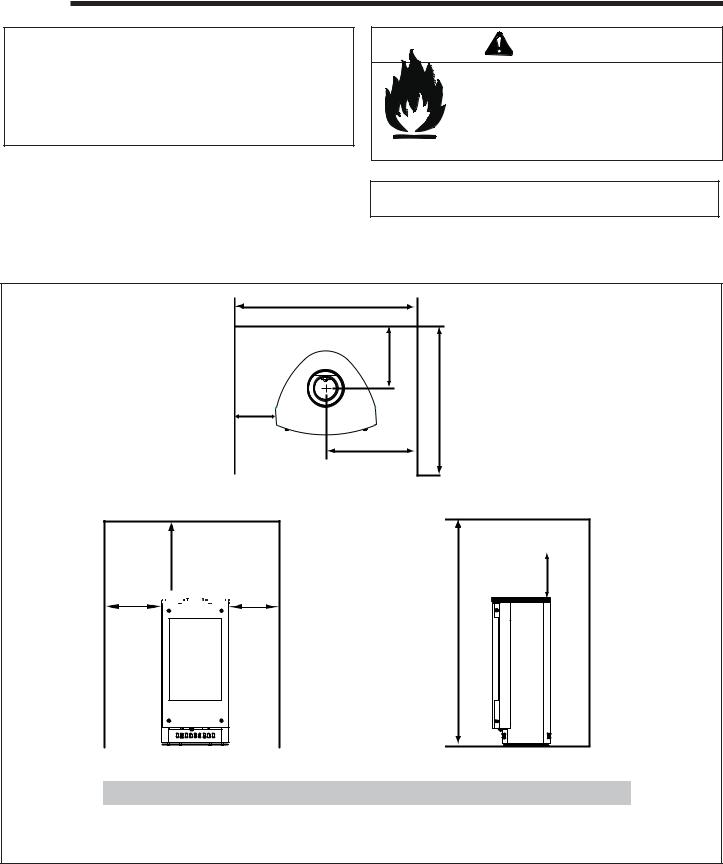
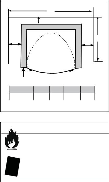
When selecting a location for your gas stove it is important to consider the required clearances to walls (see Figure 3.1).
NOTE: For actual gas stove dimensions refer to Section 12.
B. Clearances to Combustibles
F |
B |
E |
A |
I |
“A” measurement is from gas stove top, not side.
Alcove
G |
H |
A 


 A
A
D
|
A |
B |
C |
D |
E |
F |
G |
H |
I |
Centimeters |
15.2 |
25.7 |
30.8 |
137.2 |
91.4 |
78.1 |
33.7 |
33.7 |
39.4 |
|
|
|
|
|
|
|
|
|
|
Figure 3.1
6 |
Heat & Glo • VRTIKL-CE • 7031-292 Rev E • 12/07 |
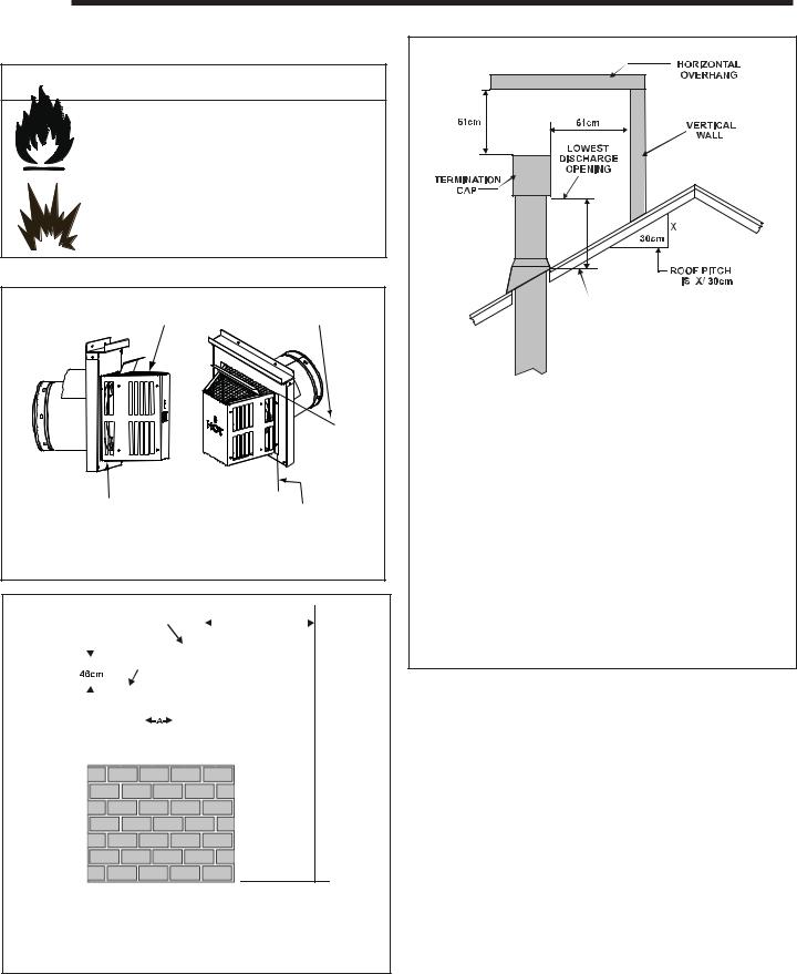
C. Optional Stone Surround Installed
|
B |
C |
|
|
|
|
|
|
|
|
|
|
|
D |
A |
|
|
|
A |
|
A |
B |
C |
D |
Centimeters |
8.3 |
10.2 |
78.1 |
91.4 |
Figure 3.1 |
|
|
|
|
 WARNING
Fire Risk.
Odor Risk.
Tipping Risk
•Install gas stove on a stable, level platform/ floor strong enough to support gas stove without tipping.
•USE wood flooring, ceramic tile, brick hearth or high pressure laminate flooring applied directly over the sub-flooring material.
|
Heat & Glo • VRTIKL-CE • 7031-292 Rev E • 12/07 |
7 |
|
4Termination Locations
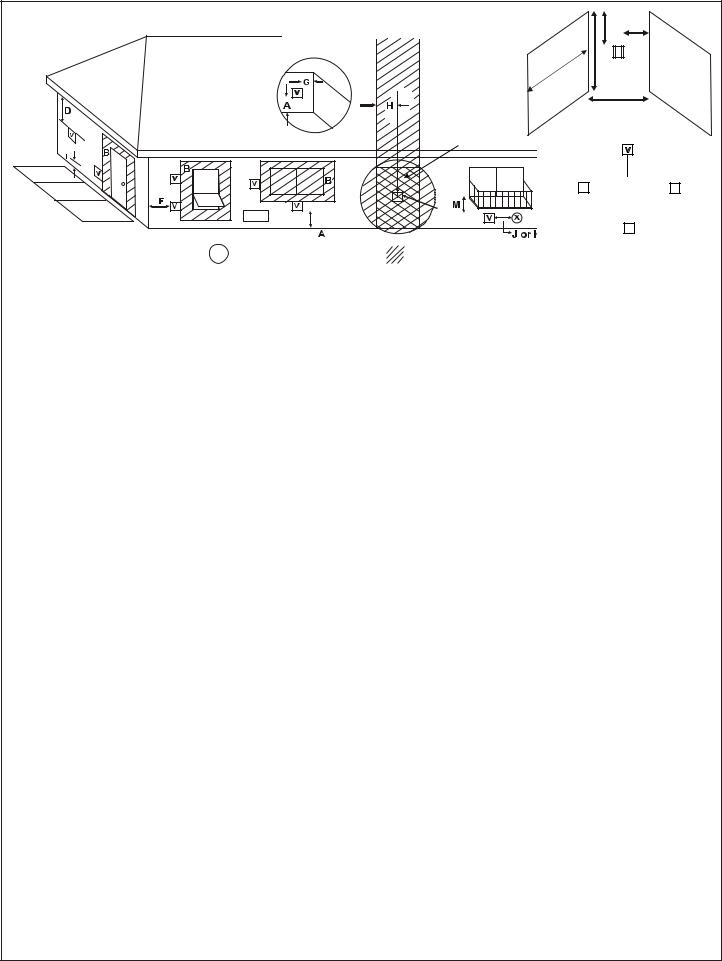
A. Flue Termination Minimum Clearances
 WARNING
Fire Risk. Explosion Risk.
Maintain flue clearance to combustibles as specified.
•Do not pack air space with insulation or other materials.
Failure to keep insulation or other materials away from flue pipe may cause fire.
Measure vertical clearances from this surface.
Measure horizontal clearances from this surface.
(See Figure 4.4 for specific clearances.)
Figure 4.1 Termination Clearances
|
|
|
GAS, WOOD OR FUEL |
|
|
|
|
|
|||||||
|
|
|
OIL TERMINATION |
|
|
|
61cm |
|
|||||||
|
|
|
|
|
|
|
|
|
|
|
|
|
|
|
|
|
|
|
|
|
|
|
|
|
|
|
|
|
(MINIMUM) TO |
||
|
|
|
|
|
|
|
|
|
|
|
|
|
PERPENDICULAR |
||
|
|
|
|
|
|
GAS |
|
|
|
|
|
WALL |
|||
|
|
|
TERMINATION |
|
|
|
(GAS ON LY) |
||||||||
|
|
|
|
|
|
|
|
|
|
|
|
|
|
|
|
|
|
|
|
|
|
|
|
|
|
|
|
|
|
|
|
|
|
|
|
|
|
|
|
|
|
|
|
|
|
|
|
|
|
|
|
|
|
|
|
|
|
|
|
|
|
|
|
|
|
|
|
|
|
|
|
|
|
|
|
|
|
|
|
|
|
|
|
|
|
|
|
|
|
|
|
|
|
|
|
H (MIN.) - MINIMUM HEIGHT FROM ROOF
TO LOWEST DISCHARGE OPENING
Roof Pitch |
H (Min.) M |
Flat to 6/12.............................................................. |
30* |
Over 6/12 to 7/12.................................................... |
38* |
Over 7/12 to 8/12.................................................... |
46* |
Over 8/12 to 9/12.................................................... |
61* |
Over 9/12 to 10/12.................................................. |
76 |
Over 10/12 to 11/12 ................................................ |
99 |
Over 11/12 to 12/12 ............................................. |
1.22 |
Over 12/12 to 14/12............................................. |
1.52 |
Over 14/12 to 16/12............................................. |
1.83 |
Over 16/12 to 18/12............................................. |
2.13 |
Over 18/12 to 20/12............................................. |
2.29 |
Over 20/12 to 21/12............................................. |
2.44 |
*.91M minimum in snow regions
Figure 4.3 Minimum Height from Roof to Lowest Discharge Opening
Figure 4.3 specifies minimum flue heights for various pitched roofs.
|
Gas Termination |
Wood & Fuel Oil Termination |
|
|
|
A |
15 cm |
51 cm |
Figure 4.2 Multiple Vertical Termination
8 |
Heat & Glo • VRTIKL-CE • 7031-292 Rev E • 12/07 |
|
|
|
|
|
|
|
|
|
|
|
|
|
|
|
|
|
|
|
|
|
|
|
|
|
|
|
|
|
|
M |
|
|
|
|
|
|
|
||
|
|
|
|
|
|
|
|
|
|
|
|
|
|
|
|
|
|
|
|
|
|
|
|
|
|
|
|
|
|
|
|
|
|
|
|||||
|
|
|
|
|
|
|
|
|
|
|
|
|
|
|
|
|
|
|
|
|
|
|
|
|
|
|
|
|
|
|
|
|
|
N |
|
|
|
|
|
|
|
|
|
|
|
|
|
|
|
|
|
|
|
|
|
|
|
|
|
|
|
|
|
|
|
|
R |
P |
|
|
|
|
|
|
|
|
|
||
|
|
|
|
|
|
|
|
|
|
|
|
|
|
|
|
|
|
|
|
|
|
|
|
|
|
|
|
|
|
|
|
|
|
|
|||||
|
|
|
|
|
|
|
|
|
|
|
|
|
|
|
|
|
|
|
|
|
|
|
|
|
|
|
|
|
|
|
|
|
|
|
|
|
|
||
|
|
|
|
|
|
|
|
|
|
|
|
|
|
|
|
|
|
|
|
|
|
|
|
|
|
|
|
|
|
|
|
|
|
|
|
|
|
|
|
|
|
|
|
|
|
|
|
|
|
|
|
|
|
|
|
|
|
|
|
|
|
|
|
|
|
|
|
|
|
|
|
|
|
|
|
|
|||
|
|
|
|
|
|
|
|
|
|
|
|
|
|
|
|
|
|
|
|
|
|
|
|
|
|
|
|
|
|
|
Q |
|
|
|
|
|
|||
|
|
|
|
|
|
|
|
|
|
|
|
|
|
|
|
|
|
|
See Notes 3 & 4 |
|
|
|
(See Note 2) |
|
|
|
|
|
|||||||||||
|
|
|
|
|
|
|
|
|
|
|
|
|
|
|
|
|
|
|
|
|
|
|
|
|
|
|
|||||||||||||
|
|
|
|
|
|
|
|
|
|
|
|
|
|
|
|
|
|
|
|
|
|
|
|
|
|
V |
|
|
|
|
|
||||||||
|
|
|
|
|
|
|
|
|
|
|
|
|
|
|
|
|
|
|
|
|
|
|
|
|
|
|
|
|
|
|
|||||||||
|
|
|
|
|
|
|
|
|
|
|
|
|
|
|
|
|
|
|
|
|
|
|
|
|
|
|
|
|
|
|
|
|
|
|
|
|
|
||
|
|
|
|
|
|
|
|
|
|
|
|
|
|
|
|
|
|
|
|
|
|
|
|
|
|
|
|
|
|
|
|
|
|
T |
S |
|
|
|
|
|
|
|
|
|
|
|
|
|
|
|
|
|
|
|
|
|
|
|
|
|
|
|
|
|
|
|
|
|
|
|
|
|
|||||||
|
|
|
|
|
|
|
|
|
|
|
|
|
|
|
|
|
|
|
|
|
|
|
|
|
|
|
V |
S |
Electrical |
|
V |
||||||||
|
|
|
|
|
|
|
|
|
|
|
|
|
|
|
|
|
|
|
|
|
|
|
|
|
|
|
|
|
Service |
|
|
||||||||
|
|
|
|
|
|
|
|
|
|
|
|
|
|
|
|
|
|
|
|
|
|
|
|
|
|
|
|
|
|
|
|
|
|
|
|
||||
|
|
|
|
|
|
|
|
|
|
|
|
|
|
|
|
|
|
|
|
|
|
|
|
|
|
|
|
|
|
|
|
|
|
|
|
|
|
|
|
|
|
|
|
|
|
|
|
|
|
|
|
|
|
|
|
|
|
|
|
|
|
|
|
|
|
|
|
|
|
|
|
|
|
D* |
|
|
|
|
|
|
|
|
|
|
|
|
|
|
|
|
|
|
|
|
|
|
|
|
|
|
|
|
|
|
|
|
|
|
|
|
|
|
|
|
|
|
|
|
|
|
|
|
|
|
|
|
|
|
|
|
|
|
|
|
|
|
|
|
|
|
|
|
|
|
|
|
|
|
|
|
|
|
V |
|
|
|
|
|
|
|
|
|
|
|
|
|
|
|
|
|
|
|
|
|
|
|
|
|
|
|
|
|
|
|
|
|
|
|
|
|
|
|
|
||||||
|
|
|
|
|
|
|
|
|
|
|
|
|
|
|
|
|
|
|
|
|
|
|
|
|
|
|
|
|
|
|
|||||||||
|
|
= VENT TERMINAL |
X = AIR SUPPLY INLET |
|
|
|
|
= AREA WHERE TERMINAL IS NOT PERMITTED |
|||||||||||||||||||||||||||||||
|
V |
|
|
|
|
||||||||||||||||||||||||||||||||||
|
|
|
|
|
|
|
|
|
|
|
|
|
|
|
|
|
|
|
|
|
|
|
|
|
|
|
|
|
|
|
|
|
|
|
|
|
|
|
|
A |
= |
|
31 cm .................... |
clearances above grade, veranda, |
|
K |
|
= |
1.8 M....................... |
|
clearance to a mechanical |
||||||||||||||||||||||||||||
|
|
|
|
|
(See Note 1) |
porch, deck or balcony |
|
|
|
|
|
|
|
|
|
|
|
|
|
|
(powered) air supply inlet |
||||||||||||||||||
|
|
|
|
|
|
L** |
|
= |
2.1 M |
|
clearance above paved |
||||||||||||||||||||||||||||
B |
= |
|
31 cm |
clearances to window or door |
|
|
|
||||||||||||||||||||||||||||||||
|
|
|
|
|
|
|
(See Note 1) |
|
sidewalk or a paved driveway |
||||||||||||||||||||||||||||||
|
|
|
|
|
|
that may be opened, or to perma- |
|
|
|
|
|
|
|
|
|
|
|
|
|
|
located on public property |
||||||||||||||||||
|
|
|
|
|
|
nently closed window. (Glass) |
|
M*** = |
46 cm ...................... |
|
clearance under veranda, porch, |
||||||||||||||||||||||||||||
D* |
= |
|
31 cm |
vertical clearance to unventilated |
|
|
|
|
|
|
|
|
|
|
|
|
|
|
deck, balcony or overhang |
||||||||||||||||||||
|
|
|
|
|
|
|
1.1 M |
|
vinyl |
|
|
|
|
|
|
|
|
|
|
|
|||||||||||||||||||
|
|
|
|
|
|
soffit or to ventilated soffit located |
|
|
|
|
|
|
|
|
|
|
|
|
|
|
|
|
|
|
|||||||||||||||
|
|
|
|
|
|
|
|
|
|
|
|
|
|
|
|
|
|
|
|
|
|
|
|
|
|
|
|
|
|
|
|
|
|||||||
|
|
|
|
|
|
above the terminal |
|
S |
= |
15 cm....................... |
|
clearance from sides of elec- |
|||||||||||||||||||||||||||
|
|
|
|
|
76 cm |
for vinyl clad soffits and below |
|
|
|
|
|
|
|
(See Note 5) |
|
trical service |
|
|
|
|
|
||||||||||||||||||
|
|
|
|
|
|
T |
= |
31 cm |
|
clearance above electrical |
|||||||||||||||||||||||||||||
|
|
|
|
|
|
electrical service |
|
|
|||||||||||||||||||||||||||||||
F |
= |
|
23 cm |
clearance to outside corner |
|
|
|
|
|
|
|
|
(See Note 5) |
|
service |
|
|
|
|
|
|
|
|
|
|
|
|||||||||||||
|
|
|
|
|
|
|
|
|
|
|
|
|
|
|
|
|
|
|
|
|
|
|
|
|
|
|
|
||||||||||||
G |
= |
|
15 cm |
clearance to inside corner |
|
|
|
Alcove Applications |
|
|
|
|
|
|
|
|
|
|
|
|
|
||||||||||||||||||
|
|
|
|
|
|
|
|
|
|
|
|
|
|
|
|
||||||||||||||||||||||||
|
|
|
N |
|
= |
|
|
15 cm |
|
non-vinyl sidewalls |
|
|
|
|
|
||||||||||||||||||||||||
|
|
|
|
|
|
|
|
|
|
|
|
|
|
|
|
|
|
|
|
|
|
|
|
||||||||||||||||
H |
= |
|
91 cm .................... |
not to be installed above a gas |
|
|
|
|
|
|
|
|
31 cm ..................... |
|
vinyl sidewalls |
|
|
|
|
|
|||||||||||||||||||
|
|
|
|
|
|
meter/regulator assembly within 90 |
|
|
P |
|
= |
|
|
2.4 M |
|
|
|
|
|
|
|
|
|
|
|
|
|
|
|||||||||||
|
|
|
|
|
|
cm horizontally from the center-line |
|
|
|
|
|
|
|
|
|
|
|
|
|
|
|
|
|
|
|
|
|
|
|
|
|
|
|
||||||
|
|
|
|
|
|
of the regulator |
|
|
|
|
|
|
|
|
|
|
|
|
|
QMIN |
|
|
|
RMAX |
|
|
|
|
|
||||||||||
I |
= |
|
1.8 M |
clearance to gas service regulator |
|
|
|
|
1 cap |
|
|
.91 M |
|
|
|
2 x Q ACTUAL |
|
|
|
||||||||||||||||||||
|
|
|
|
|
2 caps |
|
|
1.8 M |
|
|
|
1 x Q ACTUAL |
|
|
|
||||||||||||||||||||||||
|
|
|
|
|
|
vent outlet |
|
|
|
|
|
|
|
|
|
|
|
|
|||||||||||||||||||||
|
|
|
|
|
|
|
|
|
|
3 caps |
|
|
2.7 M |
|
2/3 x Q ACTUAL |
|
|
|
|||||||||||||||||||||
J |
= |
31 cm |
clearance to non-mechanical |
|
|
|
|
|
|
|
|
|
|
||||||||||||||||||||||||||
|
|
|
|
4 caps |
|
|
3.7 M |
|
1/2 x Q ACTUAL |
|
|
|
|||||||||||||||||||||||||||
|
|
|
|
|
|
air supply inlet to building or the |
|
|
|
|
|
|
|
|
|
|
|
|
|
|
|
|
|
|
|
|
|
|
|
|
|
|
|
||||||
|
|
|
|
|
|
combustion air inlet to any other |
|
|
|
QMIN = # termination caps x 3 RMAX = (2 / # termination caps) x QACTUAL |
|
|
|||||||||||||||||||||||||||
|
|
|
|
|
|
gas stove |
|
|
|
|
|
|
|
|
|
|
|
|
|
|
|
|
|
|
|
|
|
|
|
|
|
|
|
||||||
|
|
|
|
|
|
|
|
|
|
|
|
|
|
|
|
|
|
|
|
|
|
|
|
|
|
|
|
|
|
|
|
|
|||||||
|
|
|
|
|
|
|
|
|
|
|
|
|
|
|
|
|
|
|
|
|
|
|
|
|
|
|
|
|
|
|
|
|
|||||||
|
|
|
|
|
|
|
|
|
|
|
|
|
|
|
|
|
|
|
|
|
|
|
|
|
|
|
|
|
|
|
|
|
|
|
|
|
|
|
|
**a flue shall not terminate directly above a sidewalk or paved driveway which is located between two single family dwellings and serves both dwellings.
***only permitted if veranda, porch, deck or balcony is fully open on a minimum of 2 sides beneath the floor, or meets Note 2.
NOTE 1: On private property where termination is less than 7 feet above a sidewalk, driveway, deck, porch, veranda or balcony, use of a listed cap shield is suggested. (See flue components page)
NOTE 2: Termination in an alcove space (spaces open only on one side and with an overhang) are permitted with the dimensions specified for vinyl or non-vinyl siding and soffits. 1. There must be 2.7M minimum between termination caps. 2. All mechanical air intakes within 3M of a termination cap must be a minimum of 2.7M below the termination cap. 3. All gravity air intakes within 2.7M of a termination cap must be a minimum of .31M foot below the termination cap.
Figure 4.4 Minimum Clearances for Termination
NOTE 3: Local codes or regulations may require different clearances.
NOTE 4: Termination caps may be hot. Consider their proximity to doors or other traffic areas.
NOTE 5: Location of the flue termination must not interfere with access to the electrical service.
Heat & Glo assumes no responsibility for the improper performance of the gas stove when the flueing system does not meet these requirements.
Heat & Glo • VRTIKL-CE • 7031-292 Rev E • 12/07 |
9 |
5 Flue Information
A. Flue Components
These models are approved to use Simpson Dura-Vent or Hearth & Home Technologies series pipes, components and termination. Approved components are labeled for identification. This pipe is tested and listed as an approved component of the stove.
DO NOT USE FIELD-FABRICATED FLUE COMPONENTS. Refer to the flue manufacturer’s instructions.
This product is approved to be flued either horizontally, through the side wall or vertically through the roof. You may flue through a Class A or masonry chimney if an approved adapter is used.
This gas stove is a balanced flue gas stove. All combustion air must come directly from the outside of the building. The flue pipe for this unit consists of an inner and an outer pipe. The inner pipe carries the gas stove exhaust out of the system, and the outer pipe brings fresh combustion air into the gas stove.
•A round support box/wall thimble or heat shield is required when the flueing passes through a combustible wall.
•A support box or ceiling firestop is required when the flueing passes through a combustible ceiling.
•Roof flashing and a storm collar are required when flueing passes through the roof.
•Follow instructions provided with the flueing for installation of these items.
 WARNING
Fire Hazard. Explosion Risk. Asphyxiation Risk.
Do NOT connect this gas gas stove to a chimney flue serving a separate solid-fuel or gas burning gas stove.
•Flue this gas stove directly outside.
•Use separate flue system for this gas stove.
May impair safe operation of this gas stove or other gas stoves connected to the flue.
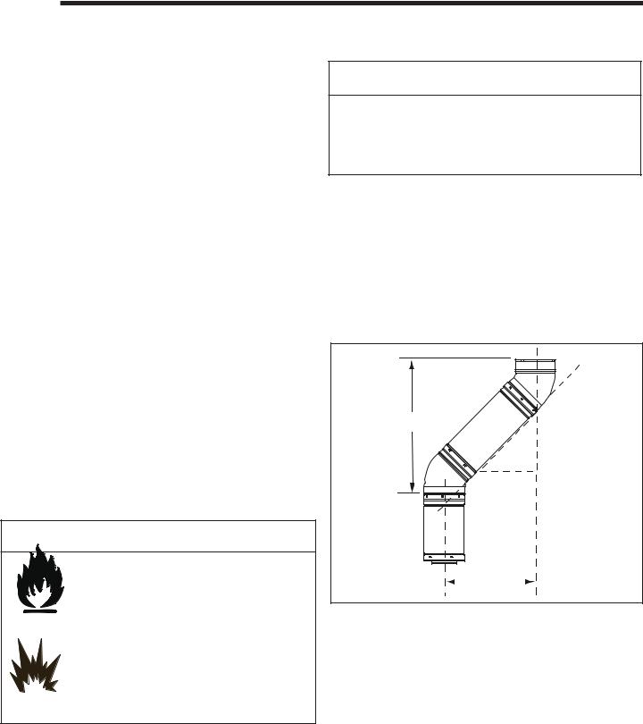
B. Use of Elbows
CAUTION
ALL flue configuration specifications MUST be followed.
•This product is tested and listed to these specifications.
•Appliance performance will suffer if specifications are not followed.
Diagonal runs have both vertical and horizontal flue aspects when calculating the effects. Use the rise for the vertical aspect and the run for the horizontal aspect. (See Figure 5.1.)
Two 45° elbows may be used in place of one 90° elbow. On 45° runs, one foot of diagonal is equal to 21.6 cm horizontal run and 21.6 cm vertical run. A length of straight pipe is allowed between two elbows. (See Figure 5.1.)
Vertical
.5 |
cm |
cm |
. |
||
30 |
|
6 |
|
21 |
21.6 cm
 Horizontal
Figure 5.1
C. Measuring Standards
Vertical and horizontal measurements were made using the following standards.
•Pipe measurements are from center line to center line.
•Horizontal terminations are measured to the outside of the mounting surface (flange of termination cap). See
Figure 4.1 on page 8.
•Horizontal pipe should be installed level with no rise.
10 |
Heat & Glo • VRTIKL-CE • 7031-292 Rev E • 12/07 |
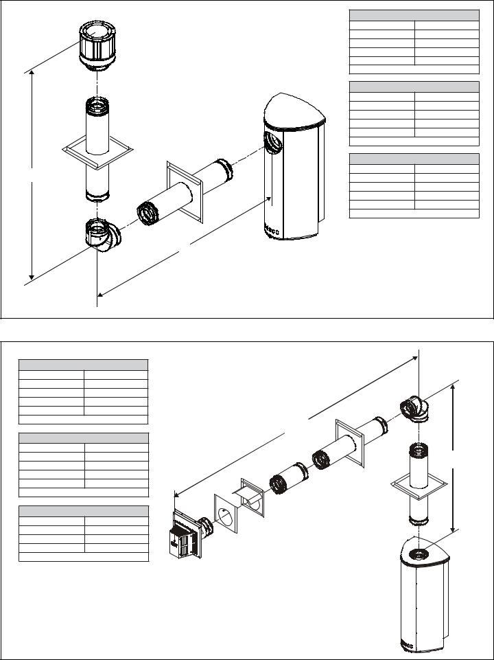
D. Flueing Diagrams
STRAIGHT UP VERTICAL FLUE V
11.8M Maximum
For Natural, Propane and Butane Gases.
Note: For this type of installation, the vertical
flue restrictor must be added. See section H V for instructions.
Figure 5.2
STRAIGHT OUT HORIZONTAL FLUE H
61cm Maximum
For Natural, Propane and Butane Gases.
H
Figure 5.3
Heat & Glo • VRTIKL-CE • 7031-292 Rev E • 12/07 |
11 |
|
Natural Gas • One 900 Elbow System |
|
|
V Minimum |
H Maximum |
|
46 cm |
1.3 M |
|
92 cm |
2.7 M |
|
1.4 M |
4.1 M |
|
1.8 M |
5.0 M |
|
V+H = Max 11.6 M |
H Max = 5.0 M |
|
Propane • One 900 Elbow System |
|
|
V Minimum |
H Maximum |
|
46 cm |
92 cm |
|
92 cm |
1.8 M |
|
1.4 M |
2.8 M |
|
1.8 M |
3.6 M |
|
V+H = Max 11.6 M |
H Max = 3.6 M |
|
Butane • One 900 Elbow System |
|
V |
V Minimum |
H Maximum |
46 cm |
46 cm |
|
|
92 cm |
92 cm |
|
1.4 M |
1.4 M |
|
1.8 M |
1.8 M |
|
V+H = Max 10 M |
H Max = 1.8 M |
|
H |
|
Figure 5.4 |
|
|
Natural Gas • One 900 Elbow System |
|
|
V Minimum |
H Maximum |
|
46 cm |
1.3 M |
|
92 cm |
2.7 M |
|
1.4 M |
4.1M |
|
1.8 M |
5.0 M |
|
V+H = Max 11 M |
H Max = 5.0 M |
H |
|
|
|
Propane • One 900 Elbow System |
|
|
V Minimum |
H Maximum |
V |
46 cm |
92 cm |
|
92 cm |
1.8 M |
|
1.4 M |
2.8 M |
|
1.8 M |
3.6 M |
|
V+H = Max 11 M |
H Max = 3.6 M |
|
Butane • One 900 Elbow System |
|
|
V Minimum |
H Maximum |
|
1.22 M |
92 cm |
|
1.4 M |
1.4 M |
|
1.8 M |
1.8 M |
|
V+H = Max 10 M |
H Max = 1.8 M |
|
Figure 5.5 |
|
|
12 |
|
Heat & Glo • VRTIKL-CE • 7031-292 Rev E • 12/07 |

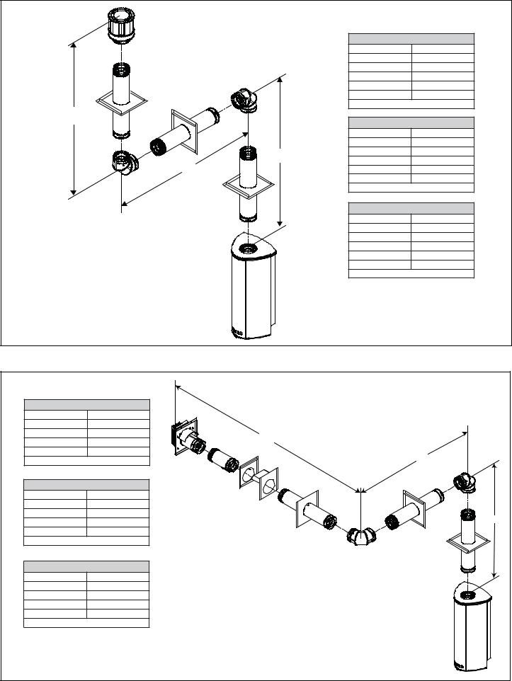
Natural Gas • Two 900 Elbows System |
|
||
V Min. |
H1 Max. |
H1 + H2 Max. |
|
46 cm |
55 cm |
1.1 M |
|
92 cm |
1.1 M |
2.2 M |
|
1.4 M |
1.7 M |
3.5 M |
|
1.8 M |
2.2 M |
4.5 M |
|
V+H1+H2 = Max 11.0M |
H1 Max = 2.2M |
H1+H2 = Max 4.5M |
|
|
|
V |
|
Propane • Two 900 Elbows System |
|
||
V Min. |
H1 Max. |
H1 + H2 Max. |
|
46 cm |
39 cm |
69 cm |
|
92 cm |
75 cm |
1.3 M |
|
1.4 M |
1.1 M |
2.1 M |
|
1.8 M |
1.5 M |
2.7 M |
|
V+H1+H2 = Max 10.6M |
H1 Max = 1.5M |
H1+H2 = Max 2.7M |
|
Butane • Two 900 Elbows System |
|
||
V Min. |
H1 Max. |
H1 + H2 Max. |
|
1.22 M |
48 cm |
61 cm |
|
1.4 M |
.5 M |
.7 M |
|
1.8 M |
.7 M |
.9 M |
|
V+H1+H2 = Max 10M |
H1 Max = .7M H1+H2 = Max .9M |
|
|
|
|
H2 |
H1 |
|
|
|
|
Figure 5.6 |
|
|
|
Natural Gas • Two 900 Elbows System |
Propane • Two 900 Elbows System |
Butane • Two 900 Elbows System |
||||||
V Min. |
H1 Max. |
H1 + H2 Max. |
V Min. |
H1 Max. |
H1 + H2 Max. |
V Min. |
H1 Max. |
H1 + H2 Max. |
46 cm |
55 cm |
1.1 M |
46 cm |
39 cm |
69 cm |
1.22 M |
48 cm |
61 cm |
92 cm |
1.1 M |
2.3 M |
92 cm |
75 cm |
1.3 M |
1.4 M |
.5 M |
.7 M |
1.4 M |
1.7 M |
3.5 M |
1.4 M |
1.1 M |
2.1 M |
1.8 M |
.7 M |
.9 M |
1.8 M |
2.2 M |
4.5 M |
1.8 M |
1.5 M |
2.7 M |
V+H1+H2 = Max 10M |
H1 Max = .7 |
H1+H2 = Max .9M |
V+H1+H2 = Max 10M |
H1 Max = 2.2M |
H1+H2 = Max 4.5M |
V+H1+H2 = Max 10M |
H1 Max = 1.5M |
H1+H2 = Max 2.7M |
|
|
|
|
|
H2 |
|
|
|
|
|
|
|
|
|
|
V |
|
|
|
|
|
|
|
|
|
H1 |
|
|
|
Figure 5.7 |
|
|
|
|
|
|
|
|
|
|
|
Heat & Glo • VRTIKL-CE • 7031-292 Rev E • 12/07 |
|
|
13 |
||
|
Natural Gas • Two 900 Elbows System |
||
|
V1 Min. |
H Max. |
|
|
31 cm |
93 cm |
|
|
61 cm |
1.8 M |
|
|
91 cm |
2.7 M |
|
|
1.2 M |
3.6 M |
|
|
1.5 M |
4.5 M |
|
V2 |
V1+V2+H = Max 11.4M |
H Max = 4.5M |
|
Propane • Two 900 Elbows System |
|||
|
|||
|
V1 Min. |
H Max. |
|
|
31 cm |
62 cm |
|
V1 |
61 cm |
1.2 M |
|
91 cm |
1.8 M |
||
H |
1.2 M |
2.4 M |
|
|
1.5 M |
3.0 M |
|
|
V1+V2+H = Max 11.4M |
H Max = 3.0M |
|
|
Butane • Two 900 Elbows System |
||
|
V1 Min. |
H Max. |
|
|
31 cm |
31 cm |
|
|
61 cm |
61 cm |
|
|
92 cm |
92 cm |
|
|
1.2 M |
1.2 M |
|
|
1.5 M |
1.5 M |
|
|
V1+V2+H = Max 10 M |
H Max = 1.0 M |
|
Figure 5.8
Natural Gas • Two 900 Elbows System |
|
||
V Min. |
H1+H2 Max. |
|
|
61 cm |
1.6 M |
|
|
91 cm |
2.4 M |
H2 |
|
1.2 M |
3.2 M |
||
|
|||
1.5 M |
4.0 M |
H1 |
|
V+H1+H2 = Max 11.4M |
H1+H2 = Max 4.0M |
||
Propane • Two 900 Elbows System |
|
||
V Min. |
H1+H2 Max. |
|
|
61 cm |
1.0 M |
|
|
91 cm |
1.5 M |
V |
|
1.2 M |
2.0 M |
||
|
|||
1.5 M |
2.6 M |
|
|
V+H1+H2 = Max 11.4M |
H1+H2 = Max 2.6M |
|
|
Butane • Two 900 Elbows System |
|
||
V1 Min. |
H1+H2 Max. |
|
|
61 cm |
42 cm |
|
|
92 cm |
64 cm |
|
|
1.2 M |
.8 M |
|
|
1.5 M |
1.0 M |
|
|
V+H1+H2 = Max 10 M |
H1+H2 = Max 1.5 M |
|
|
Figure 5.9 |
|
|
|
14 |
|
Heat & Glo • VRTIKL-CE • 7031-292 Rev E • 12/07 |
|
 Loading...