


Models:
Pier-TRC
ST-TRC
L-Corner-TRC
R-Corner-TRC
Installers Guide
Underwriters
Laboratories Listed
WARNING: IF THE INFORMATION IN THESE INSTRUCTIONS IS NOT FOLLOWED EXACTLY, A FIRE OR EXPLOSION MAY RESULT CAUSING PROPERTY DAMAGE, PERSONAL INJURY, OR DEATH.
-Do not store or use gasoline or other flammable vapors and liquids in the vicinity of this or any other appliance.
-What to do if you smell gas
•Do not try to light any appliance.
•Do not touch any electrical switch.
•Do not use any phone in your building.
•Immediately call your gas supplier from a neighbor's phone. Follow the gas supplier's instructions.
•If you cannot reach your gas supplier, call the fire department.
-Installation and service must be performed by a qualified installer, service agency, or the gas supplier.
Printed in U.S.A. Copyright 2003
Heat-N-Glo, a division of Hearth & Home Technologies Inc. 20802 Kensington Boulevard, Lakeville, MN 55044
READ THIS MANUAL BEFORE INSTALLING OR OPERATING THIS APPLIANCE. THIS INSTALLERS GUIDE MUST BE LEFT WITH APPLIANCE FOR FUTURE REFERENCE.
WARNING: IMPROPER INSTALLATION, ADJUSTMENT, ALTERATION, SERVICE OR MAINTENANCE CAN CAUSE INJURY OR PROPERTY DAMAGE. REFER TO THIS MANUAL. FOR ASSISTANCE OR ADDITIONAL INFORMATION CONSULT A QUALIFIED INSTALLER, SERVICE AGENCY, OR THE GAS SUPPLIER.
1.This appliance may be installed in an aftermarket, permanently located, manufactured (mobile) home, where not prohibited by local codes.
2.This appliance is only for use with the type of gas indicated on the rating plate. This appliance is not convertible for use with other gases, unless a certified kit is used.
Please contact your Heat-N-Glo dealer with any questions or concerns. For the number of your nearest Heat-N-Glo dealer, please call 1-888-427-3973.
This product is covered by one or more of the following patents: (United States) 4,112,913; 4,408,594; 4,422,426; 4,424,792; 4,520,791; 4,793,322; 4,852,548; 4,875,464; 5,000,162; 5,016,609; 5,076,254 5,191,877; 5,218,953; 5,328,356; 5,429,495; 5,452,708; 5,542,407; 5,613,487; (Australia) 543790; 586383; (Canada) 1,123,296; 1,297,746; 2,195,264; (Mexico) 97-0457; (New Zealand) 200265; or other U.S. and foreign patents pending.
501-900 REV. O 2/03
1

SAFETY AND WARNING INFORMATION
READ and UNDERSTAND all instructions carefully ! before starting the installation. FAILURE TO
FOLLOW these installation instructions may result in a possible fire hazard and will void the warranty.
Prior to the first firing of the fireplace, READ the
! Using Your Fireplace section of the Owners Guide.
DO NOT USE this appliance if any part has been ! under water. Immediately CALL a qualified service
technician to inspect the unit and to replace any part of the control system and any gas control which has been under water.
! THIS UNIT IS NOT FOR USE WITH SOLID FUEL.
Installation and repair should be PERFORMED by a ! qualified service person. The appliance and venting
system should be INSPECTED before initial use and at least annually by a professional service person. More frequent cleaning may be required due to excessive lint from carpeting, bedding material, etc. It is IMPERATIVE that the unit’s control compartment, burners, and circulating air passageways BE KEPT CLEAN to provide for adequate combustion and ventilation air.
Always KEEP the appliance clear and free from
!combustible materials, gasoline, and other flammable vapors and liquids.
NEVER OBSTRUCT the flow of combustion and
!ventilation air. Keep the front of the appliance CLEAR of all obstacles and materials for servicing and proper operations.
Due to the high temperature, the appliance should
!be LOCATED out of traffic areas and away from furniture and draperies. Clothing or flammable material SHOULD NOT BE PLACED on or near the appliance.
Children and adults should be ALERTED to the
!hazards of high surface temperature and should STAY AWAY to avoid burns or clothing ignition. Young children should be CAREFULLY SUPERVISED when they are in the same room as the appliance.
These units MUST use one of the vent systems ! described in the Installing the Fireplace section of
the Installers Guide. NO OTHER vent systems or components MAY BE USED.
This gas fireplace and vent assembly MUST be
! vented directly to the outside and MUST NEVER be attached to a chimney serving a separate solid fuel burning appliance. Each gas appliance MUST USE a separate vent system. Common vent systems are
PROHIBITED.
INSPECT the external vent cap on a regular basis to ! make sure that no debris is interfering with the air
flow.
! The glass door assembly MUST be in place and  sealed, and the trim door assembly MUST be in
place on the fireplace before the unit can be placed into safe operation.
DO NOT OPERATE this appliance with the glass
!door removed, cracked, or broken. Replacement of the glass door should be performed by a licensed or qualified service person. DO NOT strike or slam the glass door.
The glass door assembly SHALL ONLY be
!replaced as a complete unit, as supplied by the gas fireplace manufacturer. NO SUBSTITUTE material may be used.
DO NOT USE abrasive cleaners on the glass door
!assembly. DO NOT ATTEMPT to clean the glass door when it is hot.
Turn off the gas before servicing this appliance. It is
!recommended that a qualified service technician
perform an appliance check-up at the beginning of each heating season.
Any safety screen or guard removed for servicing
!must be replaced before operating this appliance.
DO NOT place furniture or any other combustible
!household objects within 36 inches of the fireplace front.
2
TABLE OF CONTENTS |
|
|
Safety and Warning Information ............................................... |
2 |
|
Service Parts Lists .................................................................... |
4 |
|
Section 1: Approvals and Codes ............................................ |
12 |
|
Approval Listings and Codes ..................................................... |
12 |
|
Appliance Certification ............................................................... |
12 |
|
Installation Codes ...................................................................... |
12 |
|
High Altitude Installations ............................................................ |
12 |
|
Section 2: Getting Started ...................................................... |
13 |
|
Introducing the Heat-N-Glo Gas Fireplaces ................................ |
13 |
|
Pre-installation Preparation ........................................................ |
13 |
|
Section 3: Installing the Fireplace ......................................... |
17 |
|
Step 1 |
Locating the Fireplace ................................................ |
17 |
Step 2 |
Framing the Fireplace ................................................. |
17 |
Step 3 |
Installing the Vent System ........................................... |
20 |
u A. Vent System Approvals .......................................... |
20 |
|
|
B. Installing Vent Components ................................... |
27 |
|
C. Vent Termination.................................................... |
30 |
Step 4 |
Positioning, Leveling, and |
|
|
Securing the Fireplace ................................................ |
33 |
Step 5 |
The Gas Control Systems .......................................... |
33 |
Step 6 |
The Gas Supply Line .................................................. |
34 |
Step 7 |
Gas Pressure Requirements ...................................... |
34 |
Step 8 |
Wiring the Fireplace .................................................... |
35 |
Step 9 |
Finishing ..................................................................... |
37 |
Step 10 Installing Trim, Logs, and Ember Material ..................... |
38 |
|
|
Installing the Trim ........................................................ |
38 |
|
Positioning the Logs ................................................... |
38 |
|
Shutter Settings .......................................................... |
38 |
|
Placing the Ember Material ......................................... |
38 |
Step 11 |
Before Lighting the Fireplace ...................................... |
39 |
Step 12 |
Lighting the Fireplace .................................................. |
39 |
After the Installation .................................................................... |
39 |
|
u Section 4: Maintaining and Servicing Your Fireplace ......... |
40 |
|
u = Contains updated information. |
|
|
3
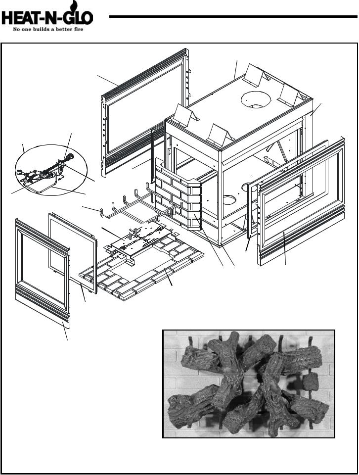
Service Parts
(NG, LP) Exploded Parts Diagram (GN, PL) Vue éclatée des pièces
Pier-TRC
Beginning Manufacturing Date: 6-97
Ending Manufacturing Date: ______
16
9
15
10
Standing Pilot
3
|
11 |
1 |
12 |
|
5 |
4 


3
7 |
14 |
9 |
6
2
8 Log Assembly
13
*Part number list on following page.
*La liste des numéros de pièce se trouve à la page suivante.
4
(NG, LP) Exploded Parts Diagram / Vue éclatée des pièces |
PIER-TRC |
IMPORTANT: THIS IS DATED INFORMATION. The most current information is located on your dealers VIP site. When ordering, supply serial and model numbers to ensure correct service parts. / IMPORTANT : L'information fournie dans cette brochure n'est valide que pendant une courte période. Les sites VIP des distributeurs disposent des renseignements les plus récents. Lors d'une commande, veuillez fournir les numéros de série et de modèles pour un remplacement adéquat des pièces.
ITEM / |
|
|
|
|
|
COMMON PART / PIÉCES COMMUNES |
SERIAL # |
PART NUMBER |
||||||
P IÈCE |
|
|
|
|
|
/ N° DE SÉRIE |
/ N° DE PIÈCE |
|||||||
|
|
|
|
|
|
|
|
|
|
|||||
|
ON/OFF Rocker Switch / Interrupteur à bascule marche/arrêt |
|
060 |
-511 |
||||||||||
1 |
Burner Orifice NG (#32DMS) / Orifice de brûleur GN (#32DMS) |
|
573 |
-800 |
||||||||||
1 |
Burner Orifice LP (1.8mm) / |
Orifice de brûleur PL (#1.8mm) |
|
501 |
-801 |
|||||||||
2 |
End Glass Assembly |
|
|
|
|
GLA-PTRC-E |
||||||||
3 |
Glass Door Assembly |
NG / |
Porte en verre |
GN |
PRE 8865 |
GLA-PTRC |
||||||||
POST 8865 |
GLA-PIER |
|||||||||||||
|
|
|
|
|
|
|
|
|
|
|
||||
3 |
Glass Door Assembly |
LP/ |
Porte en verre |
PL |
PRE 2301 |
GLA-PTRC |
||||||||
POST 2301 |
GLA-PIER |
|||||||||||||
|
|
|
|
|
|
|
|
|
|
|
||||
|
|
|
|
|
|
|
|
|
|
|
PRE 16919 |
SRV501-176A |
||
4 |
Burner Assembly NG |
/ Brûleur GN |
|
16919 to 18287 |
501 |
-173A |
||||||||
|
|
|
|
|
|
|
|
|
|
|
POST 18288 |
501 |
-272A |
|
|
|
|
|
|
|
|
|
|
|
|
PRE 3666 |
SRV501-175A |
||
4 |
Burner Assembly LP |
/ |
Brûleur PL |
|
3666 to 3984 |
501 |
-172A |
|||||||
|
|
|
|
|
|
|
|
|
|
|
POST 3985 |
501 |
-273A |
|
5 |
Log Grate |
/ |
Grille de Bûche |
|
|
501 |
-364 |
|||||||
6 |
Base Refractory |
/ |
Réfractaire Base |
|
|
SRV504-738-UM |
||||||||
7 |
Refractory, Rear |
/ |
Réfractaire |
|
|
SRV504-737-UM |
||||||||
|
NG Log Set |
Assembly (sold as complete log set only) / GN Jeu de Bûches |
PRE18287 |
LOGS-PTRC |
||||||||||
8 |
POST 18288 |
LOGS-MS |
||||||||||||
|
|
|
|
|
|
|
|
|
|
|||||
LP Log Set |
Assembly (sold as complete log set only) / PL Jeu de Bûches |
PRE 3984 |
LOGS-PTRC |
|||||||||||
|
||||||||||||||
|
POST 3985 |
LOGS-MS |
||||||||||||
|
|
|
|
|
|
|
|
|
|
|
||||
9 |
Decorative Front |
/ |
Avant décoratif |
|
|
DF-36H |
||||||||
10 |
Flex Ball Valve Assembly / |
Fléchir l'Assemblée de Soupape de Balle |
|
302 |
-320A |
|||||||||
12 |
3/8" Burner Tube |
/ |
Tube de brûleur |
|
|
570 |
-301A |
|||||||
13 |
Decorative Front |
(End) / Le Devant décoratif (la Fin) |
|
DF-PTRCE |
||||||||||
14 |
Extrusion with holes |
/ L'extrusion avec les trous |
|
464 |
-343 |
|||||||||
15 |
Surround Right |
/ |
Entourage droit |
|
|
501 |
-233 |
|||||||
16 |
Surround Left |
/ |
Entourage gauche |
|
|
501 |
-232 |
|||||||
|
Glass C lip |
/ Trombone de verre |
|
|
501 |
-235 |
||||||||
|
STANDING PILOT IGNITION ONLY / ALLUMAGE UNE VEILLEUSE SEULEMENT |
|
|
|||||||||||
|
Piezo Ignitor |
/ |
Allumage Piézo |
|
|
418 |
-513 |
|||||||
|
Junction Box |
/ |
Boîtier de raccordement |
|
|
100-250A |
||||||||
|
Valve NG |
/ |
Valve GN |
|
|
|
060 |
-522 |
||||||
|
Valve LP |
/ |
Valve PL |
|
|
|
|
060 |
-523 |
|||||
11 |
Pilot Assembly NG |
/ |
Module de veilleuse GN |
|
485 |
-510A |
||||||||
11 |
Pilot Assembly LP / |
Module de veilleuse PL |
|
485 |
-511A |
|||||||||
|
Pilot Orifice NG |
/ |
Orifice de veilleuse GN |
|
|
446 |
-505 |
|||||||
|
Pilot Orifice LP |
/ |
Orifice de veilleuse PL |
|
|
446 |
-517 |
|||||||
|
Thermocouple |
/ Thermocouple |
|
|
446 |
-511 |
||||||||
|
Thermopile |
/ |
Thermopile |
|
|
|
060 |
-512 |
||||||
|
Pilot Tube |
/ |
Tube de veilleuse |
|
|
SRV485-301 |
||||||||
|
DSI IGNITION ONLY / ALLUMAGE DSI SEULEMENT |
|
|
|
||||||||||
|
Junction Box |
/ |
Boîtier de raccordement |
|
|
100-254A |
||||||||
|
Valve NG |
/ |
Valve GN |
|
|
|
492 |
-500 |
||||||
|
Valve LP |
/ |
Valve PL |
|
|
|
|
492 |
-501 |
|||||
|
Electrode |
/ |
Électrode |
|
|
|
501 |
-591 |
||||||
|
Module / |
Module |
|
|
|
|
|
|
501 |
-592 |
||||
|
IPI IGNITION ONLY / ALLUMAGE IPI SEULEMENT |
|
|
|
||||||||||
|
Junction Box |
/ |
Boîtier de raccordement |
|
|
383 |
-250A |
|||||||
|
Valve NG |
/ |
Valve GN |
|
|
|
750 |
-500 |
||||||
|
Valve LP |
/ |
Valve PL |
|
|
|
|
750 |
-501 |
|||||
11 |
Pilot Assembly NG |
/ |
Module de veilleuse GN |
|
385 |
-510A |
||||||||
11 |
Pilot Assembly LP / |
Module de veilleuse PL |
|
385 |
-511A |
|||||||||
|
Wire Assembly |
/ Module de fil |
|
|
593 |
-590A |
||||||||
|
Module / Module |
|
|
|
|
|
|
593 |
-592 |
|||||
|
3V Plug |
|
|
|
|
|
|
|
|
|
|
593 |
-593A |
|
|
Conversion Kit NG |
/ |
Module de conversion GN |
|
NGK-MS-IPI |
|||||||||
|
Conversion Kit LP |
/ |
Module de conversion PL |
|
LPK-MS-IPI |
|||||||||
|
Pilot Tube |
/ |
Tube de veilleuse |
|
|
SRV485-301 |
||||||||
|
Battery Pack |
/ |
Paquet de Batterie(Pile) |
|
|
593 |
-594A |
|||||||
ACCESSORIES / ACCESSOIRES |
|
|
|
|
||||||||||
|
Fan Kit / |
Module de ventilateur |
|
|
GFK-160A |
|||||||||
|
Remote Control Kit |
/ |
Commande à distance |
|
RC-SMART-HNG |
|||||||||
|
Remote Control Kit |
/ |
Commande à distance |
|
SMART-STAT-HNG |
|||||||||
|
Conversion Kit NG / Module de conversion GN |
PRE 18287 |
NGK-PTRD |
|||||||||||
|
POST 18288 |
NGK-PTRCMS |
||||||||||||
|
|
|
|
|
|
|
|
|
|
|
NGK-PTRCMS-DSI |
|||
|
|
|
|
|
|
|
|
|
|
|
|
|||
|
Conversion Kit LP |
/ |
Module de conversion PL |
PRE 3984 |
LPK-PTRD |
|||||||||
|
POST 3985 |
LPK-PTRCMS |
||||||||||||
|
|
|
|
|
|
|
|
|
|
|
LPK-PTRCMS-DSI |
|||
|
|
|
|
|
|
|
|
|
|
|
|
|||
5

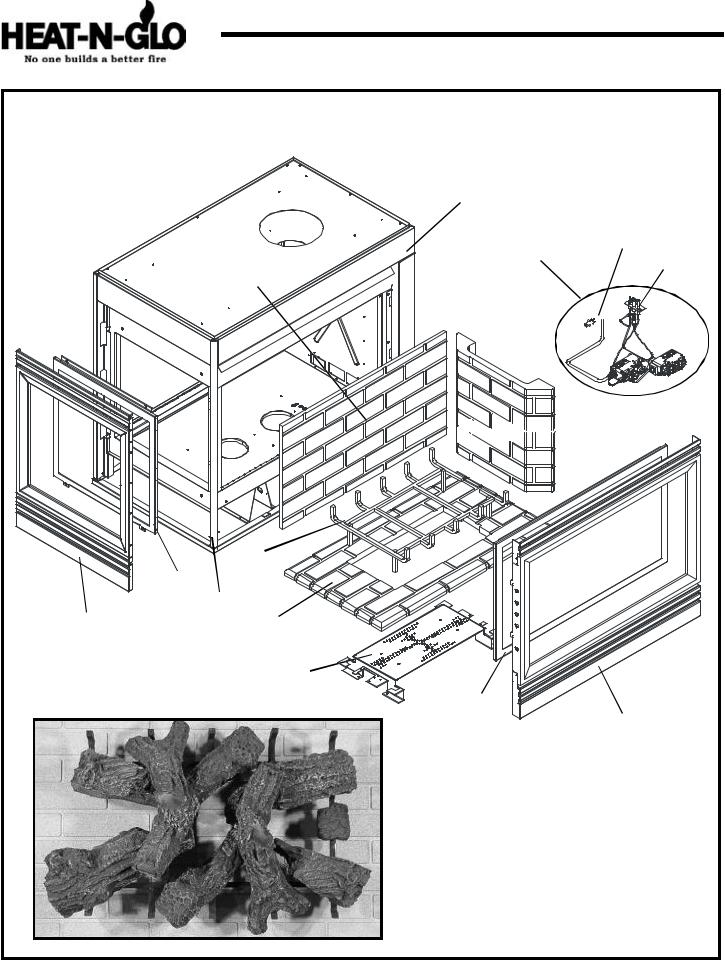
Service Parts |
ST-TRC |
(NG, LP) Exploded Parts Diagram |
Beginning Manufacturing Date: 6-97 |
(GN, PL) Vue éclatée des pièces |
Ending Manufacturing Date: ______ |
2
7
8
10 9
STANDING PILOT
4
6
11 1
2
5
3
12 Log Assembly
7
* Part number list on following page.
* La liste des numéros de pièce se trouve à la page suivante.
6
(NG, LP) Exploded Parts Diagram / Vue éclatée des pièces |
ST-TRC |
IMPORTANT: THIS IS DATED INFORMATION. The most current information is located on your dealers VIP site. When ordering, supply serial and model numbers to ensure correct service parts. / IMPORTANT : L'information fournie dans cette brochure n'est valide que pendant une courte période. Les sites VIP des distributeurs disposent des renseignements les plus récents. Lors d'une commande, veuillez fournir les numéros de série et de modèles pour un remplacement adéquat des pièces.
ITEM / |
|
|
|
|
|
|
|
COMMON PARTS / I PIÉCES COMMUNES |
|
SERIAL # |
PART NUMBER |
||||
PIÈCE |
|
|
|
|
|
|
|
/ N° DE SÉRIE |
/ N° DE PIÈCE |
||||||
|
|
|
|
|
|
|
|
|
|
|
|||||
|
ON/OFF Rocker Switch |
/ |
Interrupteur à bascule marche/arrêt |
|
|
060-511 |
|||||||||
1 |
Burner Orifice NG (#32DMS) |
/ Orifice de brûleur GN (#32DMS) |
|
|
573-800 |
||||||||||
1 |
Burner Orifice LP (1.8mm) / |
Orifice de brûleur PL (1.8mm) |
|
|
501-801 |
||||||||||
2 |
Glass Door Assembly |
NG / |
Porte en verre GN |
|
PRE |
8558 |
GLA-PTRC |
||||||||
|
POST 8558 |
GLA-PIER |
|||||||||||||
|
|
|
|
|
|
|
|
|
|
|
|
||||
2 |
Glass Door Assembly |
LP / |
Porte en verre PL |
|
PRE |
2254 |
GLA-PTRC |
||||||||
|
POST 2254 |
GLA-PIER |
|||||||||||||
|
|
|
|
|
|
|
|
|
|
|
|
||||
|
|
|
|
|
|
|
|
|
|
|
|
PRE 16067 |
SRV501-176A |
||
3 |
Burner Assembly NG |
/ Brûleur GN |
|
16067 to 18029 |
501-173A |
||||||||||
|
|
|
|
|
|
|
|
|
|
|
|
POST 18030 |
501-272A |
||
|
|
|
|
|
|
|
|
|
|
|
|
PRE 3608 |
SRV501-175A |
||
3 |
Burner Assembly LP |
/ Brûleur PL |
|
3608 to 3994 |
501-172A |
||||||||||
|
|
|
|
|
|
|
|
|
|
|
|
POST 3995 |
501-273A |
||
4 |
Log Grate |
/ |
Grille de Bûche |
|
|
|
|
501-364 |
|||||||
5 |
Base Refractory |
|
/ |
Réfractaire Base |
|
|
|
SRV504-738-UM |
|||||||
6 |
Refractory, Rear |
|
/ |
Réfractaire |
|
|
|
SRV504-737-UM |
|||||||
7 |
Decorative Front |
/ |
Avant décoratif |
|
|
|
DF-36H |
||||||||
8 |
Surround Side / Entourage gauche |
|
|
|
502-202 |
||||||||||
9 |
Flex Ball Valve Assembly / |
Fléchir l'Assemblée de Soupape de Balle |
|
|
302-320A |
||||||||||
11 |
3/8" Burner Tube |
/ |
Tube de brûleur |
|
|
|
570-301A |
||||||||
|
NG Log Set |
Assembly |
(sold as complete log set only) / |
GN Jeu de Bûches |
PRE18029 |
LOGS-PTRC |
|||||||||
12 |
POST 18030 |
LOGS-MS |
|||||||||||||
|
|
|
|
|
|
|
|
|
|
|
|||||
LP Log Set |
Assembly |
(sold as complete log set only) / |
PL Jeu de Bûches |
PRE 3994 |
LOGS-PTRC |
||||||||||
|
|||||||||||||||
|
POST 3995 |
LOGS-MS |
|||||||||||||
|
|
|
|
|
|
|
|
|
|
|
|
||||
|
Glass Clips |
/ Trombone de verre |
|
|
|
501-135 |
|||||||||
|
STANDING PILOT IGNITION ONLY / ALLUMAGE UNE VEILLEUSE SEULEMENT |
|
|
|
|||||||||||
|
Piezo Ignitor |
/ |
Allumage Piézo |
|
|
|
418-513 |
||||||||
|
Junction Box |
/ |
Boîtier de raccordement |
|
|
|
100-250A |
||||||||
|
Valve NG |
/ |
Valve GN |
|
|
|
|
|
|
060-522 |
|||||
|
Valve LP |
/ |
Valve PL |
|
|
|
|
|
|
060-523 |
|||||
|
Pilot Assembly NG |
/ |
Module de veilleuse GN |
|
|
|
485-510A |
||||||||
10 |
Pilot Assembly LP / |
Module de veilleuse PL |
|
|
|
485-511A |
|||||||||
10 |
Pilot Orifice NG |
/ |
Orifice de veilleuse GN |
|
|
|
446-505 |
||||||||
|
Pilot Orifice LP |
/ |
Orifice de veilleuse PL |
|
|
|
446-517 |
||||||||
|
Thermocouple |
/ |
Thermocouple |
|
|
|
446-511 |
||||||||
|
Thermopile |
/ |
Thermopile |
|
|
|
|
060-512 |
|||||||
|
Pilot Tube |
/ |
Tube de veilleuse |
|
|
|
SRV485-301 |
||||||||
|
DSI IGNITION ONLY / ALLUMAGE DSI SEULEMENT |
|
|
|
|
||||||||||
|
Junction Box |
/ |
Boîtier de raccordement |
|
|
|
100-254A |
||||||||
|
Valve NG |
/ |
Valve GN |
|
|
|
|
|
|
492-500 |
|||||
|
Valve LP |
/ |
Valve PL |
|
|
|
|
|
|
492-501 |
|||||
|
Electrode |
/ |
Électrode |
|
|
|
|
|
501-591 |
||||||
|
Module / |
Module |
|
|
|
|
|
|
|
|
501-592 |
||||
|
IPI IGNITION ONLY / ALLUMAGE IPI SEULEMENT |
|
|
|
|
||||||||||
|
Junction Box |
/ |
Boîtier de raccordement |
|
|
|
383-250A |
||||||||
|
Valve NG |
/ |
Valve GN |
|
|
|
|
|
|
750-500 |
|||||
|
Valve LP |
/ |
Valve PL |
|
|
|
|
|
|
750-501 |
|||||
10 |
Pilot Assembly NG |
/ |
Module de veilleuse GN |
|
|
|
385-510A |
||||||||
10 |
Pilot Assembly LP / |
Module de veilleuse PL |
|
|
|
385-511A |
|||||||||
|
Wire Assembly |
/ Module de fil |
|
|
|
593-590A |
|||||||||
|
Module / Module |
|
|
|
|
|
|
|
|
593-592 |
|||||
|
3V Plug |
|
|
|
|
|
|
|
|
|
|
|
|
593-593A |
|
|
Conversion Kit NG / Module de conversion GN |
|
|
|
NGK-MS-IPI |
||||||||||
|
Conversion Kit LP |
/ |
Module de conversion PL |
|
|
|
LPK-MS-IPI |
||||||||
|
Pilot Tube |
/ |
Tube de veilleuse |
|
|
|
SRV485-301 |
||||||||
|
Battery Pack |
/ |
Paquet de Batterie(Pile) |
|
|
|
593-594A |
||||||||
ACCESSORIES / ACCESSOIRES |
|
|
|
|
|||||||||||
|
Fan Kit / |
Module de ventilateur |
|
|
|
GFK-160A |
|||||||||
|
Remote Control Kit |
/ |
Commande à distance |
|
|
|
RC-SMART-HNG |
||||||||
|
Remote Control Kit |
/ |
Commande à distance |
|
|
|
SMART-STAT-HNG |
||||||||
|
|
|
|
|
|
|
|
|
|
|
|
PRE 18029 |
NGK-PTRD |
||
|
Conversion Kit NG / Module de conversion GN |
|
POST 18030 |
NGK-PTRCMS |
|||||||||||
|
|
|
|
|
|
|
|
|
|
|
|
NGK-PTRCMS-DSI |
|||
|
|
|
|
|
|
|
|
|
|
|
|
|
|
||
|
|
|
|
|
|
|
|
|
|
|
|
PRE 3994 |
LPK-PTRD |
||
|
Conversion Kit LP / Module de conversion PL |
|
POST 3995 |
LPK-PTRCMS |
|||||||||||
|
|
|
|
|
|
|
|
|
|
|
|
LPK-PTRCMS-DSI |
|||
|
|
|
|
|
|
|
|
|
|
|
|
|
|
||
7
Service Parts |
L-Corner-TRC |
(NG, LP) Exploded Parts Diagram |
Beginning Manufacturing Date: 6-97 |
(GN, PL) Vue éclatée des pièces |
Ending Manufacturing Date: ______ |
10
STANDING PILOT 1


 12 8
12 8 

11


 7
7
|
5 |
|
2 |
|
15 |
14 |
6 |
4
9 Log Assembly |
3 |
|
13
15
* Part number list on following page.
* La liste des numéros de pièce se trouve à la page suivante.
8
(NG, LP) Exploded Parts Diagram / Vue éclatée des pièces |
L-CORNER-TRC |
IMPORTANT: THIS IS DATED INFORMATION. The most current information is located on your dealers VIP site. When ordering, supply serial and model numbers to ensure correct service parts. / IMPORTANT : L'information fournie dans cette brochure n'est valide que pendant une courte période. Les sites VIP des distributeurs disposent des renseignements les plus récents. Lors d'une commande, veuillez fournir les numéros de série et de modèles pour un remplacement adéquat des pièces.
ITEM / |
|
|
|
|
|
|
|
COMMON PARTS / PIÉCES COMMUNES |
|
SERIAL # |
PART NUMBER |
||||
PIÈCE |
|
|
|
|
|
|
|
/ N° DE SÉRIE |
/ N° DE PIÈCE |
||||||
|
|
|
|
|
|
|
|
|
|
|
|||||
|
ON/OFF Rocker Switch |
/ |
Interrupteur à bascule marche/arrêt |
|
|
060-511 |
|||||||||
1 |
Burner Orifice NG (#32DMS) / Orifice de brûleur GN (#32DMS) |
|
|
573-800 |
|||||||||||
1 |
Burner Orifice LP (1.8mm) / |
Orifice de brûleur PL (1.8mm) |
|
|
501-801 |
||||||||||
2 |
Glass Door Assembly, End / |
Porte en verre |
|
|
|
GLA-PTRC-E |
|||||||||
3 |
Glass Door Assembly NG / |
Porte en verre GN |
|
PRE |
1957 |
GLA-PTRC |
|||||||||
|
POST 1957 |
GLA-PIER |
|||||||||||||
|
|
|
|
|
|
|
|
|
|
|
|
||||
3 |
Glass Door Assembly LP/ Porte en verre PL |
|
PRE |
1232 |
GLA-PTRC |
||||||||||
|
POST 1232 |
GLA-PIER |
|||||||||||||
|
|
|
|
|
|
|
|
|
|
|
|
||||
|
|
|
|
|
|
|
|
|
|
|
|
PRE |
2920 |
SRV501-176A |
|
4 |
Burner Assembly NG |
/ Brûleur GN |
|
2920 to 3102 |
501-173A |
||||||||||
|
|
|
|
|
|
|
|
|
|
|
|
POST |
3103 |
501-272A |
|
|
|
|
|
|
|
|
|
|
|
|
|
PRE |
1439 |
SRV501-175A |
|
4 |
Burner Assembly LP |
/ Brûleur PL |
|
1439 to 1473 |
501-172A |
||||||||||
|
|
|
|
|
|
|
|
|
|
|
|
POST |
1474 |
501-273A |
|
5 |
Log Grate |
/ |
Grille de Bûche |
|
|
|
501-364 |
||||||||
6 |
Base Refractory |
|
/ |
Réfractaire Base |
|
|
|
SRV504-738-UM |
|||||||
7 |
Refractory, Rear |
/ |
Réfractaire |
|
|
|
SRV504-737-UM |
||||||||
8 |
Refractory, Back / Réfractaire |
|
|
|
SRV504-736-UM |
||||||||||
|
NG Log Set |
Assembly |
(sold as complete log set only) |
/ GN Jeu de Bûches |
PRE 3102 |
LOGS-PTRC |
|||||||||
9 |
POST 3103 |
LOGS-MS |
|||||||||||||
|
|
|
|
|
|
|
|
|
|
|
|||||
LP Log Set |
Assembly |
(sold as complete log set only) |
/ GN Jeu de Bûches |
PRE 1473 |
LOGS-PTRC |
||||||||||
|
|||||||||||||||
|
POST 1473 |
LOGS-MS |
|||||||||||||
|
|
|
|
|
|
|
|
|
|
|
|
||||
10 |
Surround Side Left / |
|
Entourer le Côté Part |
|
|
|
501-232 |
||||||||
11 |
3/8" Burner Tube |
/ |
Tube de brûleur |
|
|
|
570-301A |
||||||||
13 |
Decorative Front |
/ |
Avant décoratif |
|
|
|
DF-36H |
||||||||
14 |
Decorative Front End |
/ |
La Fin décorative de Devant |
|
|
|
DF-PTRCE |
||||||||
15 |
Extrusion with holes |
/ L'extrusion avec les trous |
|
|
|
464-343 |
|||||||||
|
Glass Clip |
/ Trombone de verre |
|
|
|
501-135 |
|||||||||
|
Flex Ball Valve Assembly / |
Fléchir l'Assemblée de Soupape de Balle |
|
|
302-320A |
||||||||||
|
STANDING PILOT IGNITION ONLY / ALLUMAGE UNE VEILLEUSE SEULEMENT |
|
|
|
|||||||||||
|
Piezo Ignitor |
/ |
Allumage Piézo |
|
|
|
418-513 |
||||||||
|
Junction Box |
/ |
Boîtier de raccordement |
|
|
|
100-250A |
||||||||
|
Valve NG |
/ |
Valve GN |
|
|
|
|
|
060-522 |
||||||
|
Valve LP |
/ |
Valve PL |
|
|
|
|
|
|
060-523 |
|||||
12 |
Pilot Assembly NG |
/ |
Module de veilleuse GN |
|
|
|
485-510A |
||||||||
12 |
Pilot Assembly LP / |
Module de veilleuse PL |
|
|
|
485-511A |
|||||||||
|
Pilot Orifice NG |
/ |
Orifice de veilleuse GN |
|
|
|
446-505 |
||||||||
|
Pilot Orifice LP |
/ |
Orifice de veilleuse PL |
|
|
|
446-517 |
||||||||
|
Thermocouple |
/ Thermocouple |
|
|
|
446-511 |
|||||||||
|
Thermopile |
/ |
Thermopile |
|
|
|
|
060-512 |
|||||||
|
Pilot Tube |
/ |
Tube de veilleuse |
|
|
|
SRV485-301 |
||||||||
|
DSI IGNITION ONLY / ALLUMAGE DSI SEULEMENT |
|
|
|
|
||||||||||
|
Junction Box |
/ |
Boîtier de raccordement |
|
|
|
100-254A |
||||||||
|
Valve NG |
/ |
Valve GN |
|
|
|
|
|
492-500 |
||||||
|
Valve LP |
/ |
Valve PL |
|
|
|
|
|
|
492-501 |
|||||
|
Electrode |
/ |
Électrode |
|
|
|
|
|
501-591 |
||||||
|
Module / |
Module |
|
|
|
|
|
|
|
|
501-592 |
||||
|
IPI IGNITION ONLY / ALLUMAGE IPI SEULEMENT |
|
|
|
|
||||||||||
|
Junction Box |
/ |
Boîtier de raccordement |
|
|
|
383-250A |
||||||||
|
Valve NG |
/ |
Valve GN |
|
|
|
|
|
750-500 |
||||||
|
Valve LP |
/ |
Valve PL |
|
|
|
|
|
|
750-501 |
|||||
12 |
Pilot Assembly NG |
/ |
Module de veilleuse GN |
|
|
|
385-510A |
||||||||
12 |
Pilot Assembly LP / |
Module de veilleuse PL |
|
|
|
385-511A |
|||||||||
|
Wire Assembly |
/ Module de fil |
|
|
|
593-590A |
|||||||||
|
Module / Module |
|
|
|
|
|
|
|
|
593-592 |
|||||
|
3V Plug |
|
|
|
|
|
|
|
|
|
|
|
|
593-593A |
|
|
Conversion Kit NG / Module de conversion GN |
|
|
|
NGK-MS-IPI |
||||||||||
|
Conversion Kit LP |
/ |
Module de conversion PL |
|
|
|
LPK-MS-IPI |
||||||||
|
Pilot Tube |
/ |
Tube de veilleuse |
|
|
|
SRV485-301 |
||||||||
|
Battery Pack |
/ |
Paquet de Batterie(Pile) |
|
|
|
593-594A |
||||||||
ACCESSORIES / ACCESSOIRES |
|
|
|
|
|||||||||||
|
Fan Kit / |
Module de ventilateur |
|
|
|
GFK-160A |
|||||||||
|
Remote Control Kit |
/ |
Commande à distance |
|
|
|
RC-SMART-HNG |
||||||||
|
Remote Control Kit |
/ |
Commande à distance |
|
|
|
SMART-STAT-HNG |
||||||||
|
Conversion Kit NG |
/ |
Module de conversion GN |
|
PRE 3102 |
NGK-PTRD |
|||||||||
|
|
POST 3103 |
NGK-PTRCMS |
||||||||||||
|
|
|
|
|
|
|
|
|
|
|
|
||||
|
Conversion Kit LP |
/ |
Module de conversion PL |
|
PRE 1472 |
LPK-PTRD |
|||||||||
|
|
POST 1473 |
LPK-PTRCMS |
||||||||||||
|
|
|
|
|
|
|
|
|
|
|
|
||||
9

Service Parts |
R-Corner-TRC |
(NG, LP) Exploded Parts Diagram |
Beginning Manufacturing Date: 6-97 |
(GN, PL) Vue éclatée des pièces |
Ending Manufacturing Date: ______ |
11
13
10
 1
1
12
STANDING PILOT
7 


16
8
2
5
15
6
14
3
4
9 Log Assembly
*Part number list on following page.
*La liste des numéros de pièce se trouve
àla page suivante.
10
(NG, LP) Exploded Parts Diagram / Vue éclatée des pièces |
R-CORNER-TRC |
IMPORTANT: THIS IS DATED INFORMATION. The most current information is located on your dealers VIP site. When ordering, supply serial and model numbers to ensure correct service parts. / IMPORTANT : L'information fournie dans cette brochure n'est valide que pendant une courte période. Les sites VIP des distributeurs disposent des renseignements les plus récents. Lors d'une commande, veuillez fournir les numéros de série et de modèles pour un remplacement adéquat des pièces.
ITEM / |
|
|
|
|
|
|
|
COMMON PARTS / PIÉCES COMMUNES |
|
SERIAL # / |
|
PART NUMBER |
|||||
P IÈCE |
|
|
|
|
|
|
|
|
N° DE SÉRIE |
|
/ N° DE PIÈCE |
||||||
|
|
|
|
|
|
|
|
|
|
|
|
|
|
||||
|
ON/OFF Rocker Switch |
/ |
|
Interrupteur à bascule marche/arrêt |
|
|
060-511 |
||||||||||
1 |
Burner Orifice NG (#32DMS) |
/ Orifice de brûleur GN (#32DMS) |
|
|
573 |
-800 |
|||||||||||
1 |
Burner Orifice LP (1.8mm) / |
Orifice de brûleur PL (1.8mm) |
|
|
501 |
-801 |
|||||||||||
2 |
Glass Door Assembly, End / |
Porte en verre |
|
|
|
GLA-PTRC-E |
|||||||||||
3 |
Glass Door Assembly |
NG / |
Porte en verre |
GN |
PRE |
2132 |
GLA-PTRC |
||||||||||
POST 2132 |
GLA-PIER |
||||||||||||||||
|
|
|
|
|
|
|
|
|
|
|
|
|
|||||
3 |
Glass Door Assembly |
NG / |
Porte en verre |
GN |
PRE |
1240 |
GLA-PTRC |
||||||||||
POST 1240 |
GLA-PIER |
||||||||||||||||
|
|
|
|
|
|
|
|
|
|
|
|
|
|||||
|
|
|
|
|
|
|
|
|
|
|
|
|
PRE |
3178 |
SRV501-176A |
||
4 |
Burner Assembly NG |
/ Brûleur GN |
|
3178 to 3355 |
501 |
-173A |
|||||||||||
|
|
|
|
|
|
|
|
|
|
|
|
|
POST 3356 |
501-272A |
|||
|
|
|
|
|
|
|
|
|
|
|
|
|
PRE |
1427 |
SRV501-175A |
||
4 |
Burner Assembly LP |
/ |
Brûleur PL |
|
1427 to 1478 |
501 |
-172A |
||||||||||
|
|
|
|
|
|
|
|
|
|
|
|
|
POST 1479 |
501-273A |
|||
5 |
Log Grate |
/ |
Grille de Bûche |
|
|
|
|
501 |
-364 |
||||||||
6 |
Base Refractory |
/ |
Réfractaire Base |
|
|
|
SRV504-738-UM |
||||||||||
7 |
Refractory, Rear |
/ |
Réfractaire |
|
|
|
SRV504-737-UM |
||||||||||
8 |
Refractory, Back / |
Réfractaire |
|
|
|
SRV504-736-UM |
|||||||||||
|
NG Log Set |
Assembly |
/ GN Jeu de Bûches |
|
PRE 3355 |
LOGS-PTRC |
|||||||||||
9 |
|
POST 3356 |
LOGS-MS |
||||||||||||||
|
|
|
|
|
|
|
|
|
|
|
|
||||||
LP Log Set |
Assembly |
/ |
PL Jeu de Bûches |
|
PRE 1478 |
LOGS-PTRC |
|||||||||||
|
|
||||||||||||||||
|
|
POST 1479 |
LOGS-MS |
||||||||||||||
|
|
|
|
|
|
|
|
|
|
|
|
|
|||||
10 |
Flex Ball Valve Assembly |
/ Fléchir l'Assemblée de Soupape de Balle |
|
|
320 |
-320A |
|||||||||||
12 |
3/8" Burner Tube |
/ |
Tube de brûleur |
|
|
|
570 |
-301A |
|||||||||
13 |
Surround Right |
/ |
Entourage droit |
|
|
|
501 |
-232 |
|||||||||
14 |
Decorative Front End |
/ |
La Fin décorative de Devant |
|
|
DF-PTRC E |
|||||||||||
15 |
Extrusion with holes |
/ L'extrusion avec les trous |
|
|
464 |
-343 |
|||||||||||
16 |
Decorative Front |
/ |
Avant décoratif |
|
|
|
DF-36H |
||||||||||
|
Glass C lips |
/ Trombone de verre |
|
|
|
501 |
-135 |
||||||||||
|
STANDING PILOT IGNITION ONLY |
|
|
|
|
|
|||||||||||
|
Piezo Ignitor |
/ |
Allumage Piézo |
|
|
|
418 |
-513 |
|||||||||
|
Junction Box |
/ |
Boîtier de raccordement |
|
|
|
100-250A |
||||||||||
|
Valve NG |
/ |
Valve GN |
|
|
|
|
|
|
|
060 |
-522 |
|||||
|
Valve LP |
/ |
Valve PL |
|
|
|
|
|
|
|
060 |
-523 |
|||||
11 |
Pilot Assembly NG |
/ |
Module de veilleuse GN |
|
|
485 |
-510A |
||||||||||
11 |
Pilot Assembly LP / |
Module de veilleuse PL |
|
|
|
485-511A |
|||||||||||
|
Pilot Orifice NG |
/ |
Orifice de veilleuse GN |
|
|
|
446 |
-505 |
|||||||||
|
Pilot Orifice LP |
/ |
Orifice de veilleuse PL |
|
|
|
446 |
-517 |
|||||||||
|
Thermocouple |
/ |
Thermocouple |
|
|
|
446-511 |
||||||||||
|
Thermopile |
/ |
Thermopile |
|
|
|
|
060 |
-512 |
||||||||
|
Pilot Tube |
/ |
Tube de veilleuse |
|
|
|
SRV485-301 |
||||||||||
DSI IGNITION ONLY / ALLUMAGE DSI SEULEMENT |
|
|
|
|
|||||||||||||
|
Junction Box |
/ |
Boîtier de raccordement |
|
|
|
100-254A |
||||||||||
|
Valve NG |
/ |
Valve GN |
|
|
|
|
|
|
|
492 |
-500 |
|||||
|
Valve LP |
/ |
Valve PL |
|
|
|
|
|
|
|
492 |
-501 |
|||||
|
Electrode |
/ |
Électrode |
|
|
|
|
|
|
|
501 |
-591 |
|||||
|
Module / |
Module |
|
|
|
|
|
|
|
|
|
501 |
-592 |
||||
|
IPI IGNITION ONLY / ALLUMAGE IPI SEULEMENT |
|
|
|
|
||||||||||||
|
Junction Box |
/ |
Boîtier de raccordement |
|
|
|
383 |
-250A |
|||||||||
|
Valve NG |
/ |
Valve GN |
|
|
|
|
|
|
|
750 |
-500 |
|||||
|
Valve LP |
/ |
Valve PL |
|
|
|
|
|
|
|
750 |
-501 |
|||||
11 |
Pilot Assembly NG |
/ |
Module de veilleuse GN |
|
|
385 |
-510A |
||||||||||
11 |
Pilot Assembly LP / |
Module de veilleuse PL |
|
|
|
385-511A |
|||||||||||
|
Wire Assembly |
/ Module de fil |
|
|
|
593 |
-590A |
||||||||||
|
Module / Module |
|
|
|
|
|
|
|
|
|
593 |
-592 |
|||||
|
3V Plug |
|
|
|
|
|
|
|
|
|
|
|
|
|
593 |
-593A |
|
|
Conversion Kit NG |
/ |
Module de conversion GN |
|
|
|
NGK-MS-IPI |
||||||||||
|
Conversion Kit LP |
/ |
Module de conversion PL |
|
|
|
LPK-MS-IPI |
||||||||||
|
Pilot Tube |
/ |
Tube de veilleuse |
|
|
|
SRV485-301 |
||||||||||
|
Battery Pack |
/ |
Paquet de Batterie(Pile) |
|
|
|
593 |
-394A |
|||||||||
ACCESSORIES / ACCESSOIRES |
|
|
|
|
|
||||||||||||
|
Fan Kit / |
Module de ventilateur |
|
|
|
GFK-160A |
|||||||||||
|
Remote Control Kit |
/ |
Commande à distance |
|
|
RC-SMART-HNG |
|||||||||||
|
Remote Control Kit |
/ |
Commande à distance |
|
|
SMART-STAT-HNG |
|||||||||||
|
Conversion Kit NG / Module de conversion GN |
|
PRE |
3355 |
NGK-PTRD |
||||||||||||
|
|
POST 3356 |
NGK-PTRCMS |
||||||||||||||
|
|
|
|
|
|
|
|
|
|
|
|
|
NGK-PTRCMS-DSI |
||||
|
|
|
|
|
|
|
|
|
|
|
|
|
|
|
|||
|
Conversion Kit LP |
/ |
Module de conversion PL |
|
PRE |
1478 |
LPK-PTRD |
||||||||||
|
|
POST 1479 |
LPK-PTRCMS |
||||||||||||||
|
|
|
|
|
|
|
|
|
|
|
|
|
LPK-PTRCMS-DSI |
||||
|
|
|
|
|
|
|
|
|
|
|
|
|
|
|
|||
11

Approvals and
Codes
Appliance Certification
The Heat-N-Glo fireplace models discussed in this Installers Guide have been tested to certification standards and listed by the applicable laboratories.
Certification
MODELS: PIER-TRC, ST-TRC, L-CORNER-TRC, R-CORNER-TRC
LABORATORY: Underwriters Laboratories TYPE: Direct Vent Gas Fireplace STANDARD: ANSI Z21.50•CGA2.22•UL307B
Installation Codes
The fireplace installation must conform to local codes. Before installing the fireplace, consult the local building code agency to ensure that you are in compliance with all applicable codes, including permits and inspections.
In the absence of local codes, the fireplace installation must conform to the National Fuel Gas Code ANSI Z223.1 (in the United States) or the CAN/CGA-B149 Installation Codes (in Canada). The appliance must be electrically grounded in accordance with local codes or, in the absence of local codes with the National Electric Code ANSI/NFPA No. 70 (in the United States), or to the CSA C22.1 Canadian Electric Code (in Canada).
These models may be installed in a bedroom or bed-sitting room in the U.S.A. and Canada.
Heat-N-Glo Quality Systems registered by SGS ICS
High Altitude Installations
U.L. Listed gas appliances are tested and approved without requiring changes for elevations from 0 to 2,000 feet in the U. S. A. and in Canada.
When installing this appliance at an elevation above 2,000 feet, it may be necessary to decrease the input rating by changing the existing burner orifice to a smaller size. Input rate should be reduced by 4% for each 1000 feet above a 2000 foot elevation in the U.S.A. or 10% for elevations between 2000 and 4500 feet in Canada. If the heating value of the gas has been reduced, these rules do not apply. To identify the proper orifice size, check with the local gas utility.
If installing this appliance at an elevation above 4,500 feet (in Canada), check with local authorities.
12
 Loading...