


Hearth and Home Technologies SL-750TRS-IPI-E, SL-350TRS-IPI, SL-350TRS-D, SL-550TRS-IPI-E User Manual
Owner’s Manual
Installation and Operation
Models:
SL-750TRS-IPI-E
SL-550TRS-IPI-E
SL-350TRS-D
SL-350TRS-IPI
CAUTION
DO NOT DISCARD THIS MANUAL
• Important operating |
• Read, understand and follow |
• Leave this manual with |
and maintenance |
these instructions for safe |
party responsible for use |
instructions included. |
installation and operation. |
and operation. |
DO DISCARDNOT
 WARNING: If the information in these instructions is not followed exactly, a fire or explosion may result causing property damage, personal injury, or death.
•Do not store or use gasoline or other flammable vapors and liquids in the vicinity of this or any other appliance.
•What to do if you smell gas
-Do not try to light any appliance
-Do not touch any electrical switch. Do not use any phone in your building.
-Immediately call your gas supplier from a neighbor’s phone. Follow the gas supplier’s instructions.
-If you cannot reach your gas supplier, call the fire department.
•Installation and service must be performed by a qualified installer, service agency, or the gas supplier.
This appliance may be installed as an OEM installation in manufactured home (USA only) or mobile home and must be installed in accordance with the manufacturer’s instructions and the manufactured home construction and safety standard, Title 24 CFR, Part 3280 or Standard for Installation in Mobile Homes, CAN/CSA Z240MH.
This appliance is only for use with the type(s) of gas indicated on the rating plate.
 WARNING
HOT! DO NOT TOUCH.
SEVERE BURNS MAY RESULT. CLOTHING IGNITION MAY RESULT.
Glass and other surfaces are hot during operation and cool down.
• Keep children away.
•CAREFULLY SUPERVISE children in same room as appliance.
•Alert children and adults to hazards of high temperatures.
•Do NOT operate with protective barriers open or removed.
•Keep clothing, furniture, draperies and other combustibles away.
This appliance has been supplied with an integral barrier to prevent direct contact with the fixed glass panel. Do NOT operate the appliance with the barrier removed.
Contact your dealer or Hearth & Home Technologies if the barrier is not present or help is needed to properly install one.
In the Commonwealth of Massachusetts:
•installation must be performed by a licensed plumber or gas fitter;
See Table of Contents for location of additional Commonwealth of Massachusetts requirements.
Installation and service of this appliance should be performed by qualified personnel. Hearth & Home Technologies suggests NFI certified or factory trained professionals, or technicians supervised by an NFI certified professional.
Heat & Glo • SL-750TRS-IPI-E, SL-550TRS-IPI-E, SL-350TRS-D, SL-350TRS-IPI • 2120-900 Rev. D • 6/07 |
1 |
Read this manual before installing or operating this appliance.
Please retain this owner’s manual for future reference.
Congratulations
Congratulations on selecting a Heat & Glo gas appliance —an elegant and clean alternative to wood burning appliances. The Heat & Glo gas appliance you have selected is designed to provide the utmost in safety, reliability, and efficiency.
As the owner of a new appliance, you’ll want to read and carefully follow all of the instructions contained in this Owner’s Manual. Pay special attention to all Cautions and Warnings.
This Owner’s Manual should be retained for future reference. We suggest that you keep it with your other important documents and product manuals.
The information contained in this Owner’s Manual, unless noted otherwise, applies to all models and gas control systems.
Your new Heat & Glo gas appliance will give you years of durable use and trouble-free enjoyment. Welcome to the Heat & Glo family of appliance products!
Homeowner Reference Information
We recommend that you record the following pertinent information about your appliance.
Model Name: ___________________________________________ Date purchased/installed:__________________
Serial Number:__________________________________________ Location on appliance: ____________________
Dealership purchased from: _______________________________ Dealer Phone: __________________________
Notes: _______________________________________________________________________________________
_____________________________________________________________________________________________
Listing Label Information/Location The model information regarding your specific appliance can be found on the rating plate usually located in the control area of the appliance.
Type of Gas
Gas and Electric
Information
This product may be covered by one or more of the following patents: (Nos produits sont couverts par un ou plusieurs des brevets suivants): (United States) 4593510, 4686807, 4766876, 4793322, 4811534, 5000162, 5016609, 5076254, 5113843, 5191877, 5218953, 5263471, 5328356, 5341794, 5347983, 5429495, 5452708, 5542407, 5601073, 5613487, 5647340, 5688568, 5762062, 5775408, 5890485, 5931661, 5941237, 5947112, 5996575, 6006743, 6019099, 6048195, 6053165, 6145502, 6170481, 6237588, 6296474, 6374822, 6413079, 6439226, 6484712, 6543698, 6550687, 6601579, 6672860, 6688302B2, 6715724B2, 6729551, 6736133, 6748940, 6748942, D320652, D445174, D462436; (Canada)1297749, 2195264, 2225408; or other U.S. and foreign patents pending (ou autres brevets americains et etrangers en attente).
Heat & Glo, a brand of Hearth & Home Technologies, Inc.
20802 Kensington Boulevard, Lakeville, MN 55044
Not for use with solid fuel.
(Ne doit pas entre utilise avec un combustible solide).
Type of Gas (Sorte De Gaz): This appliance must be installed in accordance with local codes, if any; if not, follow ANSI Z223.1 in the USA or CAN/CGA B149 installation codes. (Installer l’appareil selon les codes ou reglements locaux ou, en l’absence de tels reglements, selon les codes d’installation CAN/CGA-B149.)
ANSI Z21XX-XXXX · CSA 2.XX-MXX · UL307B
Minimum Permissible Gas Supply for Purposes of Input Adjustment. |
|
|
|
||||||
Approved Minimum (De Gaz) Acceptable |
0.0 in w.c. |
(Po. Col. d’eau) |
|
|
|
||||
Maximum Pressure (Pression) |
|
0.0 in w.c. |
(Po. Col. d’eau) |
|
|
|
|||
Maximum Manifold Pressure (Pression) |
0.0 in w.c. |
(Po. Col. d’eau) |
|
|
|
||||
Minimum Manifold Pressure (Pression) |
0.0 in w.c. |
(Po. Col. d’eau) |
|
|
|
||||
Total Electrical Requirements: 000Vac, 00Hz., less than 00 Amperes |
MADE IN USA |
|
|
||||||
|
|
|
|
|
|
|
|
|
|
|
|
IN CANADA |
|
Model: |
XXXXXXXX |
|
|||
ALTITUDE: |
0-0000 FT. |
0000-0000FT. |
|
||||||
(Modele): |
|
||||||||
MAX. INPUT BTUH: |
00,000 |
00,000 |
|
|
|
|
|
|
|
MIN. INPUT BTUH: |
00,000 |
00,000 |
|
Serial |
XXXXXXXX |
|
|||
ORIFICE SIZE: |
#XXXXX |
#XXXXX |
|
|
|||||
|
(Serie): |
|
|||||||
Model Number
Serial Number
2 |
Heat & Glo • SL-750TRS-IPI-E, SL-550TRS-IPI-E, SL-350TRS-D, SL-350TRS-IPI • 2120-900 Rev. D • 6/07 |
Table of Contents
1 Listing and Code Approvals
A. Appliance Certification . . . . . . . . . . . . . . . . . . . . . . . . . . . . 4 B. Glass Specifications. . . . . . . . . . . . . . . . . . . . . . . . . . . . . . 4 C. BTU Specifications. . . . . . . . . . . . . . . . . . . . . . . . . . . . . . . 4 D. High Altitude Installations . . . . . . . . . . . . . . . . . . . . . . . . . . 4 E. Non-Combustible Materials Specification. . . . . . . . . . . . . . 4 F. Combustible Materials Specification . . . . . . . . . . . . . . . . . 4 G. Requirements for the Commonwealth of Massachusetts. . 5
2 Getting Started
A. Design and Installation Considerations . . . . . . . . . . . . . . . 6
B. Tools and Supplies Needed . . . . . . . . . . . . . . . . . . . . . . . . 6
C. Inspect Appliance and Components. . . . . . . . . . . . . . . . . . 6
3 Framing and Clearances
A. Selecting Appliance Location . . . . . . . . . . . . . . . . . . . . . . . 7
B. Constructing the Appliance Chase . . . . . . . . . . . . . . . . . . . 8
C. Clearances . . . . . . . . . . . . . . . . . . . . . . . . . . . . . . . . . . . . . 8
D. Elevated Hearth Systems. . . . . . . . . . . . . . . . . . . . . . . . . . 9
E. Mantel Projections . . . . . . . . . . . . . . . . . . . . . . . . . . . . . . 10
4 Termination Locations
A. Vent Termination Minimum Clearances . . . . . . . . . . . . . . .11
5 Vent Information and Diagrams
A. Vent Table Key . . . . . . . . . . . . . . . . . . . . . . . . . . . . . . . . . 13
B. Use of Elbows . . . . . . . . . . . . . . . . . . . . . . . . . . . . . . . . . 13
C. Measuring Standards . . . . . . . . . . . . . . . . . . . . . . . . . . . . 13
D. Use of Flex Vent. . . . . . . . . . . . . . . . . . . . . . . . . . . . . . . . 14
E. Vent Diagrams . . . . . . . . . . . . . . . . . . . . . . . . . . . . . . . . . 15
6 Vent Clearances and Framing
A. Pipe Clearances to Combustibles . . . . . . . . . . . . . . . . . . 25 B. Wall Penetration Framing. . . . . . . . . . . . . . . . . . . . . . . . . 25 C. Vertical Penetration Framing . . . . . . . . . . . . . . . . . . . . . . 26
7 Appliance Preparation
A. Top Vent . . . . . . . . . . . . . . . . . . . . . . . . . . . . . . . . . . . . . . 27
B. Rear Vent . . . . . . . . . . . . . . . . . . . . . . . . . . . . . . . . . . . . . 28
C. Securing and Leveling the Appliance . . . . . . . . . . . . . . . . 29
8 Installing Vent Pipe |
|
A. Assembly of Vent Sections (DVP Pipe) . . . . . . . . . . . . . . |
30 |
B. Disassembly of Vent Sections (DVP Pipe) . . . . . . . . . . . . |
32 |
C. Installing Heat Shield and Horizontal Termination Cap |
|
(DVP Pipe) . . . . . . . . . . . . . . . . . . . . . . . . . . . . . . . . . . . . |
33 |
D. Assembly of Vent Sections (SL pipe) . . . . . . . . . . . . . . . . |
34 |
E. Installing Wall Shield Firestops and Horizontal |
|
Termination Cap (SL Pipe) . . . . . . . . . . . . . . . . . . . . . . . . |
35 |
F. Installing Roof Flashing and Vertical Termination Cap. . . |
36 |
9 Gas Information
A. Fuel Conversions . . . . . . . . . . . . . . . . . . . . . . . . . . . . . . . 38
B. Gas Pressures . . . . . . . . . . . . . . . . . . . . . . . . . . . . . . . . . 38
C. Gas Connection . . . . . . . . . . . . . . . . . . . . . . . . . . . . . . . . 38
10 Electrical Information
A. Recommendation for Wire . . . . . . . . . . . . . . . . . . . . . . . . 40 B. Connecting to the Appliance. . . . . . . . . . . . . . . . . . . . . . . 40 C. Intellifire Ignition System Wiring . . . . . . . . . . . . . . . . . . . . 41 D. Standing Pilot Ignition System Wiring . . . . . . . . . . . . . . . 41 E. Junction Box Installation. . . . . . . . . . . . . . . . . . . . . . . . . . 43 F. Wall Switch Installation for Fan (Optional) . . . . . . . . . . . . 43
11 Finishing
A. Mantel Projections . . . . . . . . . . . . . . . . . . . . . . . . . . . . . . 44
B. Facing Material. . . . . . . . . . . . . . . . . . . . . . . . . . . . . . . . . 45
C. Splatter Guard . . . . . . . . . . . . . . . . . . . . . . . . . . . . . . . . . 46
D. Doors . . . . . . . . . . . . . . . . . . . . . . . . . . . . . . . . . . . . . . . . 48
12 Appliance Setup
A. Remove Shipping Materials . . . . . . . . . . . . . . . . . . . . . . . 49
B. Clean the Appliance . . . . . . . . . . . . . . . . . . . . . . . . . . . . . 49
C. Accessories . . . . . . . . . . . . . . . . . . . . . . . . . . . . . . . . . . . 49
D. Lava Rock, Mineral Wool/Ember Placement . . . . . . . . . . 49
E. Install Refractory . . . . . . . . . . . . . . . . . . . . . . . . . . . . . . . 50
F. Positioning the Logs. . . . . . . . . . . . . . . . . . . . . . . . . . . . . 51
G. Glass Assembly . . . . . . . . . . . . . . . . . . . . . . . . . . . . . . . . 57
H. Grilles and Trim . . . . . . . . . . . . . . . . . . . . . . . . . . . . . . . . 57
I. Air Shutter Setting . . . . . . . . . . . . . . . . . . . . . . . . . . . . . . 57
13 Operating Instructions
A. Before Lighting Appliance. . . . . . . . . . . . . . . . . . . . . . . . . 58 B. Lighting Appliance . . . . . . . . . . . . . . . . . . . . . . . . . . . . . . 59 C. After Appliance is Lit. . . . . . . . . . . . . . . . . . . . . . . . . . . . . 61 D. Frequently Asked Questions . . . . . . . . . . . . . . . . . . . . . . 61
14 Troubleshooting
A. Standing Pilot Ignition System . . . . . . . . . . . . . . . . . . . . . 62
B. Intellifire Ignition System . . . . . . . . . . . . . . . . . . . . . . . . . 64
15 Maintaining and Servicing Appliance
A. Maintenance Tasks. . . . . . . . . . . . . . . . . . . . . . . . . . . . . . 67
16 Reference Materials
A. Appliance Dimension Diagram. . . . . . . . . . . . . . . . . . . . . 68
B. Vent Components Diagrams . . . . . . . . . . . . . . . . . . . . . . 69
C. Service Parts List . . . . . . . . . . . . . . . . . . . . . . . . . . . . . . 76
D. Limited Lifetime Warranty. . . . . . . . . . . . . . . . . . . . . . . . . 84
E. Contact Information . . . . . . . . . . . . . . . . . . . . . . . . . . . . . 85
Î = Contains updated information.
Heat & Glo • SL-750TRS-IPI-E, SL-550TRS-IPI-E, SL-350TRS-D, SL-350TRS-IPI • 2120-900 Rev. D • 6/07 |
3 |
1 Listing and Code Approvals
A.Appliance Certification
ÎMODELS: SL-750TRS-IPI-E,SL-550TRS-IPI-E,
SL-350TRS-D, SL-350TRS-IPI
LABORATORY: Underwriters Laboratories, Inc. (UL)
TYPE: Direct Vent Gas Appliance Heater
STANDARD: ANSI Z21.88a-2007 • CSA 2.33a-2007
This product is listed to ANSI standards for “Vented Gas Appliance Heaters” and applicable sections of “Gas Burning Heating Appliances for Manufactured Homes and Recreational Vehicles”, and “Gas Fired Appliances for Use at High Altitudes”.
NOT INTENDED FOR USE AS A PRIMARY HEAT SOURCE.
This appliance is tested and approved as either supplemental room heat or as a decorative appliance. It should not be factored as primary heat in residential heating calculations.
B. Glass Specifications
Hearth & Home Technologies appliances manufactured with tempered glass may be installed in hazardous locations such as bathtub enclosures as defined by the Consumer Product Safety Commission (CPSC). The tempered glass has been tested and certified to the requirements of ANSI Z97.1 and CPSC 16 CFR 1202 (Safety Glazing Certification Council SGCC# 1595 and 1597. Architectural Testing, Inc. Reports 02-31919.01 and 02-31917.01).
This statement is in compliance with CPSC 16 CFR Section 1201.5 “Certification and labeling requirements” which refers to 15 U.S. Code (USC) 2063 stating “…Such certificate shall accompany the product or shall otherwise be furnished to any distributor or retailer to whom the product is delivered.”
Some local building codes require the use of tempered glass with permanent marking in such locations. Glass meeting this requirement is available from the factory. Please contact your dealer or distributor to order.
Note: This installation must conform with local codes. In the absence of local codes you must comply with the National Fuel Gas Code, ANSI Z223.1-latest edition in the U.S.A. and the CAN/CGA B149 Installation Codes in Canada.
Heat & Glo Quality Systems registered by SGS ICS
C. BTU Specifications
Models |
|
Maximum |
Minimum |
Orifice |
Î |
U.S. (0-2000 ft.) or |
Input |
Input |
Size |
|
|
Canada (2000-4500 ft.) |
BTU/h |
BTU/h |
(DMS) |
|
|
SL-750TRS-IPI-E (NG) |
U.S. |
30,800 |
20,200 |
#37 |
|
Canada |
27,720 |
18,180 |
#38 |
|
|
SL-750TRS-IPI-E (LP) |
U.S. |
30,700 |
23.300 |
#52 |
|
Canada |
27,630 |
20,970 |
#53 |
|
|
|
|
||||
SL-550TRS-IPI-E (NG) |
U.S. |
27,300 |
18,200 |
#40 |
|
Canada |
24,570 |
16,380 |
#41 |
|
|
SL-550TRS-IPI-E (LP) |
U.S. |
25,100 |
18,300 |
#53 |
|
Canada |
22,590 |
16,470 |
#54 |
|
|
|
|
||||
SL-350TRS-D (NG) |
U.S. |
20,500 |
14,400 |
#44 |
|
SL-350TRS-IPI (NG) |
Canada |
18,450 |
12,960 |
#45 |
|
SL-350TRS-D (LP) |
U.S. |
20,000 |
14,900 |
#55 |
|
SL-350TRS-IPI (LP) |
Canada |
18,000 |
13,410 |
#56 |
|
D. High Altitude Installations
U.L. Listed gas appliances are tested and approved without requiring changes for elevations from 0 to 2000 feet in the U.S.A. and Canada.
When installing this appliance at an elevation above 2000 feet, it may be necessary to decrease the input rating by changing the existing burner orifice to a smaller size. Input rate should be reduced by 4% for each 1000 feet above a 2000 foot elevation in the U.S.A., or 10% for elevations between 2000 and 4500 feet in Canada. If the heating value of the gas has been reduced, these rules do not apply. To identify the proper orifice size, check with the local gas utility.
If installing this appliance at an elevation above 4500 feet (in Canada), check with local authorities.
 WARNING
Do NOT use this appliance if any part has been under water. Immediately call a qualified service technician to inspect the appliance and to replace any part of the control system and any gas control which has been under water.
E. Non-Combustible Materials Specification
Material which will not ignite and burn. Such materials are those consisting entirely of steel, iron, brick, tile, concrete, slate, glass or plasters, or any combination thereof. Materials that are reported as passing ASTM E 136, Standard
Test Method for Behavior of Materials in a Vertical Tube Furnace at 750ºC, shall be considered non-com- bustible materials.
F. Combustible Materials Specification
Materials made of or surfaced with wood, compressed paper, plant fibers, plastics, or other material that can ignite and burn, whether flame proofed or not, or whether plastered or unplastered shall be considered combustible materials.
4 |
Heat & Glo • SL-750TRS-IPI-E, SL-550TRS-IPI-E, SL-350TRS-D, SL-350TRS-IPI • 2120-900 Rev. D • 6/07 |

Note: The following requirements reference various Massachusetts and national codes not contained in this document.
G.Requirements for the Commonwealth of Massachusetts
For all side wall horizontally vented gas fueled equipment installed in every dwelling, building or structure used in whole or in part for residential purposes, including those owned or operated by the Commonwealth and where the side wall exhaust vent termination is less than seven (7) feet above finished grade in the area of the venting, including but not limited to decks and porches, the following requirements shall be satisfied:
Installation of Carbon Monoxide Detectors
At the time of installation of the side wall horizontal vented gas fueled equipment, the installing plumber or gas fitter shall observe that a hard wired carbon monoxide detector with an alarm and battery back-up is installed on the floor level where the gas equipment is to be installed. In addition, the installing plumber or gas fitter shall observe that a battery operated or hard wired carbon monoxide detector with an alarm is installed on each additional level of the dwelling, building or structure served by the side wall horizontal vented gas fueled equipment. It shall be the responsibility of the property owner to secure the services of qualified licensed professionals for the installation of hard wired carbon monoxide detectors.
In the event that the side wall horizontally vented gas fueled equipment is installed in a crawl space or an attic, the hard wired carbon monoxide detector with alarm and battery back-up may be installed on the next adjacent floor level.
In the event that the requirements of this subdivision can not be met at the time of completion of installation, the owner shall have a period of thirty (30) days to comply with the above requirements; provided, however, that during said thirty (30) day period, a battery operated carbon monoxide detector with an alarm shall be installed.
Approved Carbon Monoxide Detectors
Each carbon monoxide detector as required in accordance with the above provisions shall comply with NFPA 720 and be ANSI/UL 2034 listed and IAS certified.
Signage
A metal or plastic identification plate shall be permanently mounted to the exterior of the building at a minimum height of eight (8) feet above grade directly in line with the exhaust vent terminal for the horizontally vented gas fueled heating appliance or equipment. The sign shall read, in print size no less than one-half (1/2) inch in size, “GAS
VENT DIRECTLY BELOW. KEEP CLEAR OF ALL OBSTRUCTIONS”.
Inspection
The state or local gas inspector of the side wall horizontally vented gas fueled equipment shall not approve the installation unless, upon inspection, the inspector observes carbon monoxide detectors and signage installed in accordance with the provisions of 248 CMR 5.08(2)(a)1 through 4.
Exemptions
The following equipment is exempt from 248 CMR 5.08(2)(a)1 through 4:
•The equipment listed in Chapter 10 entitled “Equipment Not Required To Be Vented” in the most current edition of NFPA 54 as adopted by the Board; and
•Product Approved side wall horizontally vented gas fueled equipment installed in a room or structure separate from the dwelling, building or structure used in whole or in part for residential purposes.
MANUFACTURER REQUIREMENTS
Gas Equipment Venting System Provided
When the manufacturer of Product Approved side wall horizontally vented gas equipment provides a venting system design or venting system components with the equipment, the instructions provided by the manufacturer for installation of the equipment and the venting system shall include:
•Detailed instructions for the installation of the venting system design or the venting system components; and
•A complete parts list for the venting system design or venting system.
Gas Equipment Venting System NOT Provided
When the manufacturer of a Product Approved side wall horizontally vented gas fueled equipment does not provide the parts for venting the flue gases, but identifies “special venting systems”, the following requirements shall be satisfied by the manufacturer:
•The referenced “special venting system” instructions shall be included with the appliance or equipment installation instructions; and
•The “special venting systems” shall be Product Approved by the Board, and the instructions for that system shall include a parts list and detailed installation instructions.
A copy of all installation instructions for all Product Approved side wall horizontally vented gas fueled equipment, all venting instructions, all parts lists for venting instructions, and/or all venting design instructions shall remain with the appliance or equipment at the completion of the installation.
See Gas Connection section for additional Commonwealth of Massachusetts requirements.
Heat & Glo • SL-750TRS-IPI-E, SL-550TRS-IPI-E, SL-350TRS-D, SL-350TRS-IPI • 2120-900 Rev. D • 6/07 |
5 |
2 Getting Started
A. Design and Installation Considerations |
C. Inspect Appliance and Components |
|
Heat & Glo direct vent gas appliances are designed to |
WARNING |
|
operate with all combustion air siphoned from outside of |
||
the building and all exhaust gases expelled to the out- |
Inspect appliance and components for damage. |
|
side. No additional outside air source is required. |
||
|
Damaged parts may impair safe operation. |
|
CAUTION |
• Do NOT install damaged components. |
|
• Do NOT install incomplete components. |
||
|
||
|
• Do NOT install substitute components. |
|
Check building codes prior to installation. |
Report damaged parts to dealer. |
•Installation MUST comply with local, regional, state and national codes and regulations.
|
• Consult local building, fire officials or authorities having jurisdic- |
• |
Carefully remove the appliance and components from |
|||
|
tion about restrictions, installation inspection, and permits. |
|
the packaging. |
|||
|
|
|
|
• The vent system components and trim doors are shipped |
||
When planning an appliance installation, it’s necessary to |
|
in separate packages. |
||||
determine the following information before installing: |
• |
The gas logs may be packaged separately and must be |
||||
• |
Where the appliance is to be installed. |
|
field installed. |
|||
• |
The vent system configuration to be used. |
• |
Report to your dealer any parts damaged in shipment, |
|||
• |
Gas supply piping. |
|
|
particularly the condition of the glass. |
||
|
• |
Read all of the instructions before starting the insta- |
||||
• |
Electrical wiring. |
|
||||
|
|
llation. Follow these instructions carefully during the |
||||
• |
Framing and finishing details. |
|
||||
|
installation to ensure maximum safety and benefit. |
|||||
• |
Whether optional accessories—devices such as a fan, |
|
|
|
||
|
wall switch, or remote control—are desired. |
|
|
WARNING |
||
|
|
|
|
|
|
|
|
|
|
WARNING |
|
|
Hearth & Home Technologies disclaims any |
|
|
|
|
|
responsibility for, and the warranty will be voided |
|
|
Keep appliance dry. |
|
|
by, the following actions: |
||
|
|
• |
Installation and use of any damaged appliance or vent |
|||
|
• |
Mold or rust may cause odors. |
|
|||
|
|
|
system component. |
|||
|
• |
Water may damage controls. |
|
|
||
|
|
• |
Modification of the appliance or vent system. |
|||
|
|
|
|
|
||
|
|
|
|
|
• |
Installation other than as instructed by Hearth & Home |
B. Tools and Supplies Needed |
|
|
Technologies. |
|||
Before beginning the installation be sure that the following |
|
• Improper positioning of the gas logs or the glass door. |
||||
|
• Installation and/or use of any component part not approved |
|||||
tools and building supplies are available. |
|
|||||
|
|
by Hearth & Home Technologies. |
||||
|
|
|
|
|
|
|
Reciprocating saw |
Framing material |
|
Any such action may cause a fire hazard. |
|||
Pliers |
|
Hi temp caulking material |
|
|
|
|
Hammer |
|
Gloves |
|
|
|
|
Phillips screwdriver |
Framing square |
|
|
|
||
Flat blade screwdriver |
Electric drill and bits (1/4 in.) |
|
|
|
||
Plumb line |
|
Safety glasses |
|
|
|
|
Level |
|
1/2 - 3/4 inch length, #6 or #8 Self-drilling screws |
||||
Manometer |
|
Voltmeter |
|
|
|
|
Tape measure |
|
Noncorrosive leak check solution |
|
|
|
|
One 1/4 inch female connection (for optional fan).
6 |
Heat & Glo • SL-750TRS-IPI-E, SL-550TRS-IPI-E, SL-350TRS-D, SL-350TRS-IPI • 2120-900 Rev. D • 6/07 |
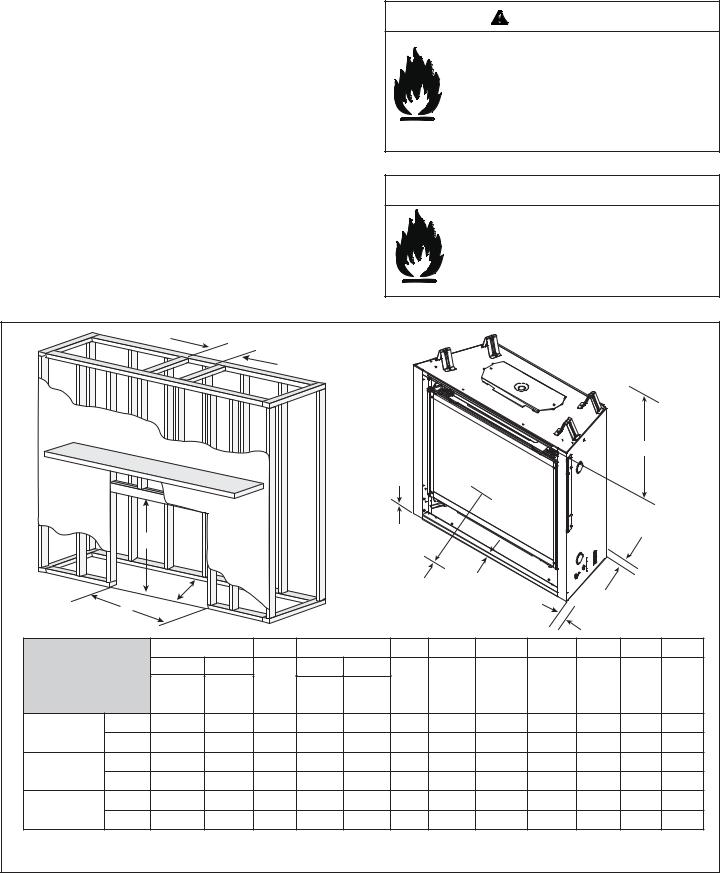
3 Framing and Clearances
Note:
•Illustrations reflect typical installations and are FOR DESIGN PURPOSES ONLY.
•Illustrations/diagrams are not drawn to scale.
•Actual installation may vary due to individual design preference.
A.Selecting Appliance Location
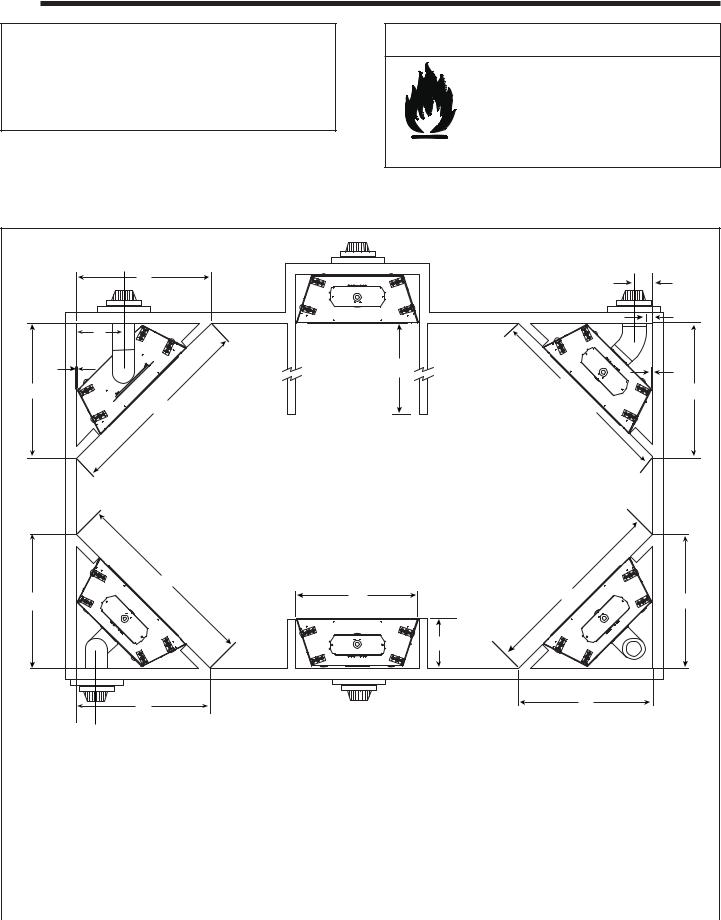
When selecting a location for your appliance it is important to consider the required clearances to walls (see Figure 3.1).
 WARNING
Fire Risk
Provide adequate clearance:
•Around air openings
•To combustibles
• For service access
Locate appliance away from traffic areas.
NOTE: For actual appliance dimensions refer to Section 16.
|
|
A |
|
|
N |
|
|
|
|
|
|
|
|
L |
|
|
E |
|
|
|
|
|
|
|
F |
|
D |
|
F |
|
|
|
|
||
|
|
|
|
|
|
A |
|
|
C |
C |
A |
|
|
|
|
||
|
|
|
|
|
In addition to these framing dimensions, also reference the following sections:
•Clearances and Mantel Projections (Section 3.C and 3.D)
•Vent Clearances and Framing (Section 6).
K
J |
B |
H |
|
|
I
J |
G |
 M
M 
G
|
Models |
A |
B |
C |
D |
E |
F |
G |
H |
I |
J |
K |
L |
M |
N |
|
|
|
Min. |
Min. |
|
||||||||||||||
|
|
|
|
|
|
|
|
|
|
|
|
|
|
|
|
||
|
SL-750TRS-IPI-E |
in. |
45-1/2 |
42 |
64-3/8 |
|
1 |
1/2 |
45-1/2 |
64-3/8 |
16-1/4 |
48-1/2 |
68-3/4 |
16-5/8 |
7-1/2 |
9 |
|
|
|
|
|
|
|
|
|
|
|
|
|
|
|
|
|
|
|
|
mm |
1155 |
1067 |
1635 |
|
25 |
13 |
1155 |
1635 |
413 |
1232 |
1737 |
422 |
191 |
229 |
|
|
|
|
|
|
||||||||||||||
|
|
|
|
|
|
See Section |
|
|
|
|
|
|
|
|
|
|
|
|
|
in. |
42 |
37 |
59-1/2 |
1 |
1/2 |
44 |
62-1/4 |
16-1/4 |
48-1/2 |
68-3/4 |
15-1/16 |
7-1/2 |
7-1/8 |
|
|
|
SL-550TRS-IPI-E |
|
|
|
|
E for Alcove |
|
|
|
|
|
|
|
|
|
|
|
|
mm |
1067 |
940 |
1511 |
25 |
13 |
1117 |
1581 |
413 |
1232 |
1737 |
383 |
191 |
181 |
|
||
|
|
Installation |
|
||||||||||||||
|
SL-350TRS-D |
in. |
39-1/2 |
34 |
55-7/8 |
|
1 |
1/2 |
44 |
62-1/4 |
16-1/4 |
48-1/2 |
68-3/4 |
13-1/2 |
7-1/2 |
6 |
|
|
|
|
|
|
|
|
|
|
|
|
|
|
|
|
|
|
|
|
mm |
1003 |
864 |
1413 |
|
25 |
13 |
1117 |
1581 |
413 |
1232 |
1737 |
343 |
191 |
152 |
|
|
|
|
|
|
||||||||||||||
|
Figure 3.1 Appliance Locations |
|
|
|
|
|
|
|
|
|
|
|
|
|
|||
|
|
|
|
|
|
|
|
|
|
|
|
|
|
|
|
|
|
|
|
Heat & Glo • SL-750TRS-IPI-E, SL-550TRS-IPI-E, SL-350TRS-D, SL-350TRS-IPI • 2120-900 Rev. D • 6/07 |
|
7 |
|||||||||||||
B. Constructing the Appliance Chase
A chase is a vertical boxlike structure built to enclose the gas appliance and/or its vent system. Vertical vents that run on the outside of a building may be, but are not required to be, installed inside a chase.
Construction of the chase may vary with the type of building. These instructions are not substitutes for the requirements of local building codes. Local building codes MUST be checked.
Chases should be constructed in the manner of all outside walls of the home to prevent cold air drafting problems. The chase should not break the outside building envelope in any manner.
Walls, ceiling, base plate and cantilever floor of the chase should be insulated. Vapor and air infiltration barriers should be installed in the chase as per regional codes for the rest of the home. Additionally, in regions where cold air infiltration may be an issue, the inside surfaces may be sheetrocked and taped for maximum air tightness.
To further prevent drafts, the wall shield and ceiling firestops should be caulked with high temperature caulk to seal gaps. Gas line holes and other openings should be caulked with high temp caulk or stuffed with unfaced
insulation. If the appliance is being installed on a cement slab, a layer of plywood may be placed underneath to prevent conducting cold up into the room.
C. Clearances
WARNING
Fire Risk.
Odor Risk.
•Install appliance on hard metal or wood surfaces extending full width and depth of appliance.
•Do NOT install appliance directly on carpeting, vinyl, tile or any combustible material other than wood.
 WARNING
Fire Risk.
•Construct chase to all clearance specifications in manual.
•Locate and install appliance to all clearance
specifications in manual.
A |
MEASURE FROM |
|
TOP OF UNIT OPENING |
|
OR FROM TOP OF HOOD |
|
|
|
|
|
|
|
|
|
|
|
|
E |
|
|
|
|
|
|
|
|
F |
|
|
|
|
|
|
|
B |
|
|
|
|
|
|
|
|
|
|
H |
|
|
|
|
|
|
|
|
|
|
|
|
|
|
|
|
|
C |
|
|
|
|
J |
G |
|
|
|
|
|
|
|
|
|
|
|
|
|
|
|
|
|
||
|
D |
|
|
|
|
|
|
|
|
I |
|
|
|
|
|
|
|
|
|
|
|
|
|
|
|
|
|
|
|
A |
|
B |
C |
|
D |
E |
F |
G |
H |
I |
J |
|
Models |
DVP PIPE |
SL PIPE |
Rough |
*DVP PIPE |
SL PIPE |
Rough |
Clearance |
|
|
|
|
|
|
Rough |
Rough |
Rough |
Rough |
Combustible |
Combustible |
Behind |
Sides of |
Front of |
||||
|
|
Opening |
Opening |
to Ceiling |
Floor |
Flooring |
Appliance |
Appliance |
Appliance |
||||
|
|
Opening |
Opening |
(Height) |
Opening |
Opening |
(Width) |
|
|||||
|
|
|
|
|
|
|
|
||||||
|
|
(Width) |
(Width) |
|
(Depth) |
(Depth) |
|
|
|
|
|
|
|
|
Inches |
10 |
8-5/8 |
38-1/4 |
28-1/4 |
16-1/4 |
42 |
32 |
0 |
0 |
1/2 |
1/2 |
36 |
|
SL-750TRS-IPI-E |
254 |
219 |
971 |
699 |
413 |
1067 |
813 |
0 |
0 |
13 |
13 |
915 |
|
Millimeters |
||||||||||||
|
Inches |
10 |
8-5/8 |
34-3/4 |
28-1/4 |
16-1/4 |
37 |
32 |
0 |
0 |
1/2 |
1/2 |
36 |
|
SL-550TRS-IPI-E |
254 |
219 |
882 |
699 |
413 |
940 |
813 |
0 |
0 |
13 |
13 |
915 |
|
Millimeters |
||||||||||||
|
Inches |
10 |
8-5/8 |
32-3/4 |
28-1/4 |
16-1/4 |
34 |
32 |
0 |
0 |
1/2 |
1/2 |
36 |
|
SL-350TRS-D |
254 |
219 |
832 |
699 |
413 |
864 |
813 |
0 |
0 |
13 |
13 |
915 |
|
Millimeters |
||||||||||||
|
* Dimension when rear venting with one 90º elbow |
|
|
|
|
|
|
|
|
|
|
||
|
Figure 3.2 Clearances to Combustibles |
|
|
|
|
|
|
|
|
|
|
|
|
8 |
Heat & Glo • SL-750TRS-IPI-E, SL-550TRS-IPI-E, SL-350TRS-D, SL-350TRS-IPI • 2120-900 Rev. D • 6/07 |
|
|
||||||||||
D. Elevated Hearth Systems
Use the table below to identify the hearth system that will be used. The table will also help identify effects on the various dimensions. Some hearth systems will elevate the appliance off the floor at a given dimension. For example, if appliance will be used with a Kenwood Cabinet with Base, the appliance will be elevated 9-1/4 inches. The 9-1/4 inch elevation will also have to be added to the following: Extension Wall Hole referenced in Figure 6.3 (Exterior Wall Hole) and Rough Opening Height (header height) referenced in Figure 3.2. NOTE: Finished floor thickness should also be considered when determining installation dimensions.
|
|
|
ELEVATED APPLIANCE |
MARBLE LEG CUT |
|
MODEL |
DESCRIPTION |
PART # |
DIMENSION |
LENGTH |
|
|
|
|
See Note 1 |
See Note 2 |
|
|
KENWOOD CABINET |
KDC44SBP |
0 |
27 3/8 in. |
|
SL-350 |
KENWOOD CABINET W/ BASE |
KDC44SBP W/ HTKDC44SBP |
9 1/4 in. |
27 3/8 in. |
|
KENWOOD CORNER CABINET |
KDA44SBP |
0 |
27 3/8 in. |
||
|
|||||
|
KENWOOD CORNER CABINET W/ BASE |
KDA44SBP W/ HTKDA44SBP |
9 1/4 in. |
27 3/8 in. |
|
|
KENWOOD CABINET |
KDC44SBP |
0 |
29-3/8 in. |
|
|
KENWOOD CABINET W/ BASE |
KDC44SBP W/ HTKDC44SBP |
9-1/4 in. |
29-3/8 in. |
|
|
KENWOOD CORNER CABINET |
KDA44SBP |
0 |
29-3/8 in. |
|
|
KENWOOD CORNER CABINET W/ BASE |
KDA44SBP W/ HTKDA44SBP |
9-1/4 in. |
29-3/8 in. |
|
|
KENWOOD MANTEL |
AFKDMPA |
0 (See Note 3) |
27-3/8 in. |
|
|
KENWOOD MANTEL W/ BASE |
AFKDMPA W/ HTKDMPA |
9 1/4 in. |
29-3/8 in. |
|
|
LAURENT SURROUND |
LAURENT-32 |
1-1/2 in. |
N/A |
|
|
CAMDEN SURROUND |
CAM550PG |
0 |
N/A |
|
|
CAMDEN SURROUND W/HEARTH |
CAM550PGH |
1-3/4 in. |
N/A |
|
|
CAMDEN SURROUND W/MANTEL |
CAMM550PG |
0 |
N/A |
|
SL-550 |
CAMDEN SURROUND W/MANTEL & |
CAMM550PGH |
1-3/4 in. |
N/A |
|
|
HEARTH |
|
|
|
|
|
ESSEX SURROUND |
ESSEX550PG |
0 |
N/A |
|
|
ESSEX SURROUND W/HEARTH |
ESSEX550PGH |
1-3/4 in. |
N/A |
|
|
ESSEX SURROUND W/MANTEL |
ESSEXM550PG |
0 |
N/A |
|
|
ESSEX SURROUND W/MANTEL & |
ESSEXM550PGH |
1-3/4 in. |
N/A |
|
|
HEARTH |
||||
|
|
|
|
||
|
MONROE SURROUND |
MON550PG |
0 |
N/A |
|
|
MONROE SURROUND W/HEARTH |
MON550PGH |
1-3/4 in. |
N/A |
|
|
MONROE SURROUND W/MANTEL |
MONM550PG |
0 |
N/A |
|
|
MONROE SURROUND W/MANTEL & |
MONM550PGH |
1-3/4 in. |
N/A |
|
|
HEARTH |
||||
|
|
|
|
||
|
KENWOOD CABINET |
KDC48DBP |
0 |
32-7/8 in. |
|
|
KENWOOD CABINET W/ BASE |
KDC48DBP W/ HTKDC48DBP |
9-1/4 in. |
32-7/8 in. |
|
|
KENWOOD CORNER CABINET |
KDA48SBP |
0 |
32-7/8 in. |
|
|
KENWOOD CORNER CABINET W/ BASE |
KDA48SBP W/ HTKDA48SBP |
9-1/4 in. |
32-7/8 in. |
|
|
KENWOOD MANTEL |
AFKDMPB |
0 (See Note 3) |
27-3/8 in. |
|
|
KENWOOD MANTEL W/ BASE |
AFKDMPB W/ HTKDMPB |
9-1/4 in. |
29-3/8 in. |
|
|
LAURENT SURROUND |
LAURENT-36 |
1-1/2 in. |
N/A |
|
|
CAMDEN SURROUND |
CAM36PG |
0 |
N/A |
|
|
CAMDEN SURROUND W/HEARTH |
CAM36PGH |
1-3/4 in. |
N/A |
|
|
CAMDEN SURROUND W/MANTEL |
CAMM36PG |
0 |
N/A |
|
SL-750 |
CAMDEN SURROUND W/MANTEL & |
CAMM36PGH |
1-3/4 in. |
N/A |
|
|
HEARTH |
|
|
|
|
|
ESSEX SURROUND |
ESSEX36PG |
0 |
N/A |
|
|
ESSEX SURROUND W/HEARTH |
ESSEX36PGH |
1-3/4 in. |
N/A |
|
|
ESSEX SURROUND W/MANTEL |
ESSEXM36PG |
0 |
N/A |
|
|
ESSEX SURROUND W/MANTEL & |
ESSEXM36PGH |
1-3/4 in. |
N/A |
|
|
HEARTH |
||||
|
|
|
|
||
|
MONROE SURROUND |
MON36PG |
0 |
N/A |
|
|
MONROE SURROUND W/HEARTH |
MON36PGH |
1-3/4 in. |
N/A |
|
|
MONROE SURROUND W/MANTEL |
MONM36PG |
0 |
N/A |
|
|
MONROE SURROUND W/MANTEL & |
MONM36PGH |
1-3/4 in. |
N/A |
|
|
HEARTH |
||||
|
|
|
|
NOTE 1. Add dimensions to Exterior Wall Hole (Figure 6.3) and Rough Opening Height (Figure 3.2). NOTE 2. Verify Marble Cut Lengths on site prior to cutting.
NOTE 3. Dimensions assume use of a 3/4 in. Hearth Pad.
Heat & Glo • SL-750TRS-IPI-E, SL-550TRS-IPI-E, SL-350TRS-D, SL-350TRS-IPI • 2120-900 Rev. D • 6/07 |
9 |
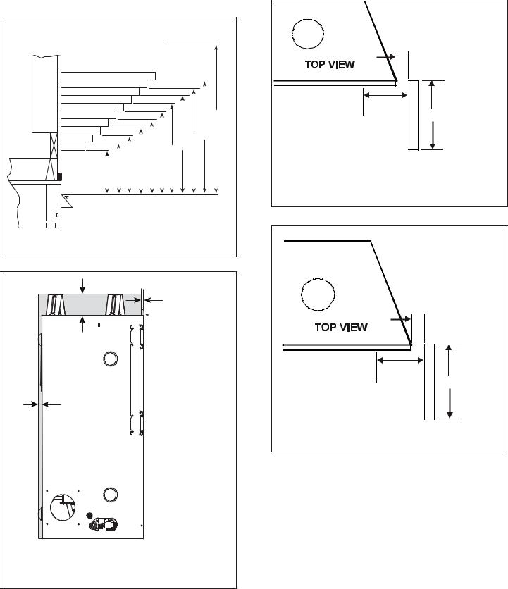
E. Mantel Projections
All measurements are in inches.
|
|
|
|
|
|
|
|
|
|
|
|
CEILING |
|||
|
|
|
|
|
12 |
|
|
|
|
|
|
|
|
|
|
|
|
|
10 |
11 |
|
|
|
|
|
|
|
|
|
|
|
|
|
|
|
|
|
|
|
|
|
|
|
|
|||
|
|
|
|
|
|
|
|
|
|
|
|
|
|
||
7 |
8 |
9 |
|
|
|
|
|
|
|
|
|
|
32 |
||
|
|
|
|
|
|
|
|
|
|||||||
|
|
|
|
|
|
|
|
|
|
|
|||||
|
|
|
|
|
|
|
|
|
|
|
|
||||
6 |
|
|
|
|
|
|
|
|
|
|
|
|
|
|
|
|
|
|
|
|
|
|
|
|
|
|
|
|
|
||
5 |
|
|
|
|
|
|
|
|
|
|
|
|
|
|
|
|
|
|
|
|
|
|
|
|
|
12 13 |
|
||||
4 |
|
|
|
|
|
|
|
|
|
|
|
|
|||
3 |
|
|
|
|
|
|
|
|
|
|
10 11 |
|
|
|
|
|
|
|
|
|
|
|
|
|
|
|
|
|
|||
|
|
|
|
|
|
|
|
9 |
|
|
|
|
|||
|
|
|
|
|
|
8 |
|
|
|
|
|||||
|
|
|
|
|
|
|
|
|
|
|
|
||||
|
|
|
|
|
7 |
|
|
|
|
|
|
||||
|
|
|
|
|
|
|
|
|
|
|
|
|
|
|
|
|
|
|
6 |
|
|
|
|
|
|
|
|
|
|
||
|
|
5 |
|
|
|
|
|
|
|
|
|
|
|
||
4 |
|
|
|
|
|
|
|
|
|
|
|
||||
|
|
|
|
|
|
|
|
|
|
|
|
|
|
||
|
|
|
|
|
|
|
|
|
|
|
|
|
|
||
|
|
|
|
|
|
|
|
|
|
|
|
|
|
|
|
 TOP OF HOOD OR FIREPLACE OPENING
Figure 3.3 Clearances to mantels or other combustibles above appliance
|
1/2 in. |
3-1/2 in. |
SHEETROCK |
 NON-COMBUSTIBLE
BOARD SHIPPED
WITH APPLIANCE
1/2 in.
 NON-COMBUSTIBLE ZONE
Figure 3.4 Non-Combustible Zone
 1/2 IN.
MINIMUM
2-7/8 IN.
MINIMUM 3 FT. MAXIMUM
Note: Clearance from opening to perpendicular wall.
Figure 3.5 Clearances to Mantel Legs or Wall Projections (Acceptable on both sides of opening.)
 3 IN.
3 IN.
MINIMUM
5-3/8 IN.
MINIMUM UNLIMITED
Note: Clearance from opening to perpendicular wall.
Figure 3.6 Wall Projection (Acceptable on one side of opening.)
10 |
Heat & Glo • SL-750TRS-IPI-E, SL-550TRS-IPI-E, SL-350TRS-D, SL-350TRS-IPI • 2120-900 Rev. D • 6/07 |
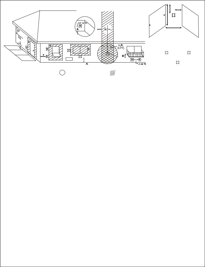
4 Termination Locations
A. Vent Termination Minimum Clearances
 WARNING
Fire Risk. Explosion Risk.
Maintain vent clearance to combustibles as specified.
•Do not pack air space with insulation or other materials.
Failure to keep insulation or other materials away from vent pipe may cause fire.
Measure vertical clearances from this surface.
Measure horizontal clearances from this surface.
(See Figure 4.4 for specific clearances)
Figure 4.1
|
|
HORIZONTAL |
|
|
OVERHANG |
2 FT. |
20 INCHES MIN. |
VERTICAL |
MIN. |
|
|
|
WALL |
|
|
LOWEST |
|
|
|
|
|
DISCHARGE |
|
|
OPENING |
|
GAS DIRECT VENT |
|
|
TERMINATION CAP |
|
|
|
|
X |
|
|
12 |
|
|
ROOF PITCH |
|
|
IS X/ 12 |
|
H (MIN.) - MINIMUM HEIGHT FROM ROOF |
|
|
TO LOWEST DISCHARGE OPENING |
|
Roof Pitch |
H (Min.) Ft. |
Flat to 6/12........................................................... |
1.0* |
Over 6/12 to 7/12................................................. |
1.25* |
Over 7/12 to 8/12................................................. |
1.5* |
Over 8/12 to 9/12................................................. |
2.0* |
Over 9/12 to 10/12............................................... |
2.5 |
Over 10/12 to 11/12 ............................................. |
3.25 |
Over 11/12 to 12/12 ............................................. |
4.0 |
Over 12/12 to 14/12............................................. |
5.0 |
Over 14/12 to 16/12............................................. |
6.0 |
Over 16/12 to 18/12............................................. |
7.0 |
Over 18/12 to 20/12............................................. |
7.5 |
Over 20/12 to 21/12............................................. |
8.0 |
* 3 foot minimum in snow regions
Figure 4.2 Minimum height from roof to lowest discharge opening
Figure 4.2 specifies minimum vent heights for various pitched roofs.
GAS, WOOD OR FUEL |
|
OIL TERMINATION |
B |
|
GAS
C TERMINATION
 A
A
|
|
|
|
|
|
|
|
|
|
|
Gas |
Wood & Fuel Oil |
|
Comments |
|
Termination |
Termination |
|
|
|
|
|
||
A |
6 in. |
20 in. min. |
Horizontal distance between terminations |
|
B |
20 in. |
24 in. min. |
Distance to perpendicular wall |
|
C |
18 in. |
18 in. |
Vertical distance between terminations |
|
Figure 4.3 Multiple Vertical Termination
Heat & Glo • SL-750TRS-IPI-E, SL-550TRS-IPI-E, SL-350TRS-D, SL-350TRS-IPI • 2120-900 Rev. D • 6/07 |
11 |
|
|
|
|
|
|
|
|
|
|
|
|
|
|
|
|
|
|
|
|
|
|
|
|
|
|
|
M |
|
|
|
|
|
|
|||||
|
|
|
|
|
|
|
|
|
|
|
|
|
|
|
|
|
|
|
|
|
|
|
|
|
|
|
|
|
|
|
|
|||||||
|
|
|
|
|
|
|
|
|
|
|
|
|
|
|
|
|
|
|
|
|
|
|
|
|
|
|
|
|
|
|
|
|
N |
|
|
|
|
|
|
|
|
|
|
|
|
|
|
|
|
|
|
|
|
|
|
|
|
|
|
|
|
R |
|
|
P |
|
|
|
|
|
|
|
|
|
|
|
|
|
|
|
|
|
|
|
|
|
|
|
|
|
|
|
|
|
|
|
|
|
|
|
|
|
|
|
|
|
|
|
|
|
|
|
|
|
||
|
|
|
|
|
|
|
|
|
|
|
|
|
|
|
|
|
|
|
|
|
|
|
|
|
|
|
|
|
|
|
|
|
|
|
|
|
||
|
|
|
|
|
|
|
|
|
|
|
|
|
|
|
|
|
|
|
|
|
|
|
|
|
|
|
|
|
|
|
|
|
|
|
|
|
||
|
|
|
|
|
|
|
|
|
|
|
|
|
|
|
|
|
|
|
|
|
|
|
|
|
|
|
|
|
|
|
|
|
|
|||||
|
|
|
|
|
|
|
|
|
|
|
|
|
|
|
|
|
|
|
|
|
|
|
|
|
|
|
|
|
Q |
|
|
|
|
|||||
|
|
|
|
|
|
|
|
|
|
|
|
|
|
|
|
|
|
|
|
|
|
|
|
|
(See Note 2) |
|
|
|
|
|||||||||
|
|
|
|
|
|
|
|
|
|
|
|
|
|
|
|
|
|
|
|
|
|
|
|
|
|
|
|
|
|
|
|
|
|
|
|
|
|
|
|
|
|
|
|
|
|
|
|
|
|
|
|
|
|
|
|
|
|
|
|
|
|
|
|
|
|
|
|
|
|
|
V |
|
|
|
|
|
|
|
|
|
|
|
|
|
|
|
|
|
|
|
|
|
|
|
|
|
|
|
|
|
|
|
|
|
|
|
|
|
|
|
T |
|
|
|
|
|
|
|
|
|
|
|
|
|
|
|
|
|
|
|
|
|
|
|
|
|
|
|
|
|
|
|
|
|
|
|
|
|
|
|
|
|
|
||
|
|
|
|
|
|
|
|
|
|
|
|
|
|
|
|
|
|
|
|
|
|
|
|
V |
|
S |
Electrical |
S |
V |
|||||||||
|
|
|
|
|
|
|
|
|
|
|
|
|
|
|
|
|
|
|
|
|
|
|
|
|
|
|
Service |
|
||||||||||
|
|
|
|
|
|
|
|
|
|
|
|
|
|
|
|
|
|
|
|
|
|
|
|
|
||||||||||||||
|
|
|
|
|
|
|
|
|
|
|
|
|
|
|
|
|
|
|
|
|
|
|
|
|
|
|
|
|
|
|
|
|
||||||
|
|
|
|
|
|
|
|
|
|
|
|
|
|
|
|
|
|
|
|
|
|
|
|
|
|
|
|
|
|
|
|
|
|
|
|
|
|
|
|
|
|
|
|
|
|
|
|
|
|
|
|
|
|
|
|
|
|
|
|
|
|
|
|
|
|
|
|
|
|
|
|
D* |
|
|
|
|
|
|
|
|
|
|
|
|
|
|
|
|
|
|
|
|
|
|
|
|
|
|
|
|
|
|
|
|
|
|
|
|
||||||||
|
|
|
|
|
|
|
|
|
|
|
|
|
|
|
|
|
|
|
|
|
|
|
|
|
|
|
|
|
|
|
|
|
|
|
|
|
|
|
|
|
|
|
|
|
|
|
|
|
|
|
|
|
|
|
|
|
|
|
|
|
|
|
|
|
|
|
|
|
|
|
V |
|
|
|
|
||
|
|
|
|
|
|
|
|
|
|
|
|
|
|
|
|
|
|
|
|
|
|
|
|
|
|
|
|
|
|
|
||||||||
|
|
|
|
|
|
|
|
|
|
|
|
|
|
|
|
|
|
|
|
|
|
|
|
|
|
|
|
|
|
|
||||||||
|
|
= VENT TERMINAL |
X = AIR SUPPLY INLET |
|
|
|
|
|
= AREA WHERE TERMINAL IS NOT PERMITTED |
|||||||||||||||||||||||||||||
|
V |
|
|
|
|
|
||||||||||||||||||||||||||||||||
|
|
|
|
|
|
|
|
|
|
|
|
|
|
|
|
|
|
|
|
|
|
|
|
|
|
|
|
|
|
|
|
|
|
|
|
|
|
|
A |
= |
12 inches................. |
clearances above grade, veranda, |
|
L** |
= |
7 ft.......................... |
|
clearance above paved |
|||||||||||||||||||||||||||||
|
|
|
(See Note 1) |
porch, deck or balcony |
|
|
|
|
|
|
|
(See Note 1) |
|
sidewalk or a paved driveway |
||||||||||||||||||||||||
B |
= |
12 inches |
clearances to window or door |
|
|
|
|
|
|
|
|
|
|
|
|
|
located on public property |
|||||||||||||||||||||
|
M*** = |
18 inches |
|
clearance under veranda, porch, |
||||||||||||||||||||||||||||||||||
|
|
|
|
that may be opened, or to perma- |
|
|
||||||||||||||||||||||||||||||||
|
|
|
|
nently closed window. (Glass) |
|
|
|
|
|
|
|
|
|
|
|
|
|
deck, balcony or overhang |
||||||||||||||||||||
D* |
= |
18 inches................. |
vertical clearance to unventilated |
|
|
|
|
|
|
|
42 inches ............... |
|
vinyl |
|
|
|
|
|
|
|
|
|
|
|
|
|||||||||||||
|
|
|
|
soffit or to ventilated soffit located |
|
S |
= |
|
6 inches................. |
|
clearance from sides of electri- |
|||||||||||||||||||||||||||
|
|
|
|
above the terminal |
|
|
|
|
|
|
|
|
(See Note 5) |
|
cal service |
|
|
|
|
|
|
|
|
|
|
|
|
|||||||||||
|
|
|
*30 inches................ |
for vinyl clad soffits and below |
|
T |
= |
12 inches................ |
|
clearance above electrical |
||||||||||||||||||||||||||||
|
|
|
|
electrical service |
|
|
|
|
|
|
|
(See Note 5) |
|
service |
|
|
|
|
|
|
|
|
|
|
|
|
||||||||||||
F |
= |
9 inches.................. |
clearance to outside corner |
|
|
|
|
|
|
|
|
|
|
|
|
|
|
|
|
|
|
|
|
|
|
|
|
|
|
|
|
|
||||||
|
|
|
|
Alcove Applications |
|
|
|
|
|
|
|
|
|
|
|
|
|
|
|
|
||||||||||||||||||
G |
= |
...................6 inches |
clearance to inside corner |
|
|
|
|
|
|
|
|
|
|
|
|
|
|
|
|
|
|
|||||||||||||||||
|
|
|
N |
|
|
= |
6 inches |
|
non-vinyl sidewalls |
|
|
|
||||||||||||||||||||||||||
H |
= |
3 ft. (Canada) |
not to be installed above a gas |
|
|
|
|
|
|
|
|
|
||||||||||||||||||||||||||
|
|
|
|
|
|
|
|
12 inches |
|
vinyl sidewalls |
|
|
|
|
||||||||||||||||||||||||
|
|
|
|
meter/regulator assembly within 3 |
|
|
|
|
|
|
|
|
|
|
|
|
|
|||||||||||||||||||||
|
|
|
|
|
|
|
P |
|
|
= |
8 ft. |
|
|
|
|
|
|
|
|
|
|
|
|
|
|
|
|
|
||||||||||
|
|
|
|
feet (90 cm) horizontally from the |
|
|
|
|
|
|
|
|
|
|
|
|
|
|
|
|
|
|
|
|
|
|
||||||||||||
|
|
|
|
center-line of the regulator |
|
|
|
|
|
|
|
|
|
|
|
|
|
|
|
|
|
|
|
|
|
|
|
|
|
|
|
|
|
|||||
|
|
|
|
|
|
|
|
|
|
|
|
|
|
|
|
QMIN |
|
|
|
|
|
|
|
RMAX |
|
|
|
|||||||||||
I |
= |
3 ft........................... |
clearance to gas service regulator |
|
|
|
|
|
|
|
|
|
|
|
|
|
|
|
|
|
|
|
|
|
||||||||||||||
|
|
|
|
|
|
|
1 cap |
|
3 feet |
|
|
|
|
2 x Q ACTUAL |
|
|
||||||||||||||||||||||
|
|
|
|
vent outlet |
|
|
|
|
|
|
|
|
|
|
|
|
|
|||||||||||||||||||||
J |
= |
9 inches (U.S.A.) |
|
|
|
|
|
|
|
|
|
|
|
|
|
2 caps |
|
6 feet |
|
|
|
|
1 x Q ACTUAL |
|
|
|||||||||||||
|
|
|
12 inches (Canada) clearance to non-mechanical |
|
|
|
|
|
|
|
|
|
|
|
|
|
|
|
|
|
|
|
|
|
|
|
|
|
|
|
|
|
||||||
|
|
|
|
|
|
|
|
|
|
3 caps |
|
9 feet |
|
|
2/3 x Q ACTUAL |
|
|
|||||||||||||||||||||
|
|
|
|
air supply inlet to building or the |
|
|
|
|
|
|
|
|
|
|
|
|||||||||||||||||||||||
|
|
|
|
combustion air inlet to any other |
|
|
|
|
|
|
|
4 caps |
|
12 feet |
|
|
1/2 x Q ACTUAL |
|
|
|||||||||||||||||||
|
|
|
|
appliance |
|
|
|
|
|
|
|
|
|
|
|
|
|
|
|
|
|
|
|
|
|
|
|
|
|
|
|
|
|
|||||
K |
= |
3 ft. (U.S.A.) |
|
|
|
|
|
QMIN = # termination caps x 3 |
RMAX = (2 / # termination caps) x QACTUAL |
|
|
|||||||||||||||||||||||||||
|
|
|
|
|
|
|
|
|
|
|
|
|
||||||||||||||||||||||||||
|
|
|
...........6 ft. (Canada) |
clearance to a mechanical (pow- |
|
|
|
|
|
|
|
|
|
|
|
|
|
|
|
|
|
|
|
|
|
|
|
|
|
|
|
|
|
|||||
|
|
|
|
|
|
|
|
|
|
|
|
|
|
|
|
|
|
|
|
|
|
|
|
|
|
|
|
|
|
|
|
|||||||
|
|
|
|
ered) air supply inlet |
|
|
|
|
|
|
|
|
|
|
|
|
|
|
|
|
|
|
|
|
|
|
|
|
|
|
|
|
|
|||||
|
|
|
|
|
|
|
|
|
|
|
|
|
|
|
|
|
|
|
|
|
|
|
|
|
|
|
|
|
|
|
|
|
|
|
|
|
|
|
**a vent shall not terminate directly above a sidewalk or paved driveway which is located between two single family dwellings and serves both dwellings.
***only permitted if veranda, porch, deck or balcony is fully open on a minimum of 2 sides beneath the floor, or meets Note 2.
NOTE 1: On private property where termination is less than 7 feet above a sidewalk, driveway, deck, porch, veranda or balcony, use of a listed cap shield is suggested. (See vents components page)
NOTE 2: Termination in an alcove space (spaces open only on one side and with an overhang) are permitted with the dimensions specified for vinyl or non-vinyl siding and soffits. 1. There must be 3 feet minimum between termination caps. 2. All mechanical air intakes within 10 feet of a termination cap must be a minimum of 3 feet below the termination cap. 3. All gravity air intakes within 3 feet of a termination cap must be a minimum of 1 foot below the termination cap.
Figure 4.4 Minimum Clearances for Termination
NOTE 3: Local codes or regulations may require different clearances.
NOTE 4: Termination caps may be hot. Consider their proximity to doors or other traffic areas.
NOTE 5: Location of the vent termination must not interfere with access to the electrical service.
WARNING: In the U.S: Vent system termination is NOT permitted in screened porches. You must follow side wall, overhang and ground clearances as stated in the instructions.
In Canada: Vent system termination is NOT permitted in screened porches. Vent system termination is permitted in porch areas with two or more sides open. You must follow all side walls, overhang and ground clearances as stated in the instructions.
Heat & Glo assumes no responsibility for the improper performance of the appliance when the venting system does not meet these requirements.
CAUTION: IF EXTERIOR WALLS ARE FINISHED WITH VINYL SIDING, IT IS SUGGESTED THAT A VINYL PROTECTOR KIT BE INSTALLED.
12 |
Heat & Glo • SL-750TRS-IPI-E, SL-550TRS-IPI-E, SL-350TRS-D, SL-350TRS-IPI • 2120-900 Rev. D • 6/07 |

5 Vent Information and Diagrams
A. Vent Table Key
The abbreviations listed in this vent table key are used in the vent diagrams.
Symbol |
Description |
|
|
|
|
V1 |
First section (closest to appliance) of vertical length |
Vertical |
|
in. |
|
V2 |
|
|
. |
1/2-8 |
|
Second section of vertical length |
12 |
in |
|||
|
|||||
H1 |
First section (closest to appliance) of horizontal length |
|
|
||
|
|
|
|||
H2 |
Second section of horizontal length |
8-1/2 in. |
|
||
|
|
|
|||
|
WARNING |
Horizontal |
|
||
|
Fire Hazard. |
|
|
|
|
|
Explosion Risk. |
Figure 5.1 |
|
|
|
|
Asphyxiation Risk. |
|
|
||
|
|
|
|
||
|
Do NOT connect this gas appliance to a chimney |
C. Measuring Standards |
|
|
|
|
flue serving a separate solid-fuel or gas burning |
|
|
||
|
appliance. |
Vertical and horizontal measurements listed in the vent |
|||
|
• Vent this appliance directly outside. |
||||
|
diagrams were made using the following standards. |
||||
|
• Use separate vent system for this appliance. |
||||
|
1. Pipe measurements are shown using the effective length |
||||
|
May impair safe operation of this appliance or |
||||
|
of pipe (see Figure 5.2). |
|
|
||
|
other appliances connected to the flue. |
|
|
||
|
|
2. Measurements are made from the appliance outer wrap, |
|||
B. Use of Elbows |
not from the standoffs. |
|
|
||
3. Horizontal terminations are measured to the outside |
|||||
|
|
||||
|
CAUTION |
mounting surface (flange of termination cap) (see |
|||
|
Figure 4.1). |
|
|
||
ALL vent configuration specifications MUST be followed. |
4. Vertical terminations are measured to bottom of termi- |
||||
nation cap. |
|
|
|||
• This product is tested and listed to these specifications. |
|
|
|||
5. Horizontal pipe installed level with no rise. |
|||||
• Appliance performance will suffer if specifications are not |
|||||
followed. |
|
|
|
||
Diagonal runs have both vertical and horizontal vent as- |
|
Pipe |
Effective Length |
|
|
Inches |
Millimeters |
||
|
|
|||
pects when calculating the effects. Use the rise for the |
|
DVP4 |
4 |
102 |
vertical aspect and the run for the horizontal aspect (see |
|
DVP6 |
6 |
152 |
Figure 5.1). |
Effective |
DVP12 |
12 |
305 |
Two 45º elbows may be used in place of one 90º elbow. On |
Height/Length |
DVP24 |
24 |
610 |
|
||||
|
DVP36 |
36 |
914 |
|
45º runs, one foot of diagonal is equal to 8.5 inches hori- |
|
|||
|
DVP48 |
48 |
1219 |
|
zontal run and 8.5 inches vertical run. A length of straight |
|
|||
|
DVP6A |
3 to 6 76 to 152 |
||
pipe is allowed between two 45º elbows (see Figure 5.1). |
|
|||
|
DVP12A |
3 to 12 |
76 to 305 |
|
|
|
|||
|
|
DVP12MI |
3 to 12 |
76 to 305 |
|
|
DVP24MI |
3 to 24 |
76 to 610 |
|
Figure 5.2 DVP Pipe Effective Length |
|
|
|
Heat & Glo • SL-750TRS-IPI-E, SL-550TRS-IPI-E, SL-350TRS-D, SL-350TRS-IPI • 2120-900 Rev. D • 6/07 |
|
13 |
||
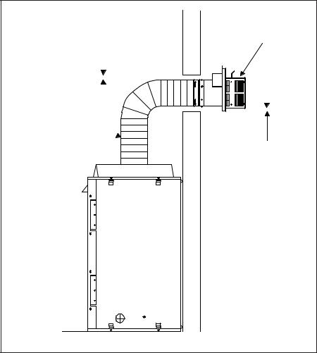
D. Use of Flex Vent
The flex vent must be supported with the spacing between support intervals not exceeding 4 feet, with no more than ½ inch sag between supports.
A support is required at each change in venting direction, and in any location where it is necessary to maintain the necessary clearance to combustibles. A simple “up and out” installation (Figure 5.3) requires only enough support to maintain the necessary clearance to combustibles. However, the vent attachment point and the firestop location are considered to be supports.
|
|
|
|
|
TERMINATION |
||||
3 in. CLEARANCE |
|
|
CAP |
||||||
|
|
|
|
|
|
|
|
|
|
|
|
|
|
|
|
|
|
|
|
|
|
|
|
|
|
|
|
|
|
|
|
|
|
|
|
|
|
|
|
|
|
|
|
|
|
|
|
|
|
|
|
|
|
|
|
|
|
|
|
|
|
|
|
|
|
|
|
|
|
FLEX-VENT 
1 in. CLEARANCE
Figure 5.3
14 |
Heat & Glo • SL-750TRS-IPI-E, SL-550TRS-IPI-E, SL-350TRS-D, SL-350TRS-IPI • 2120-900 Rev. D • 6/07 |
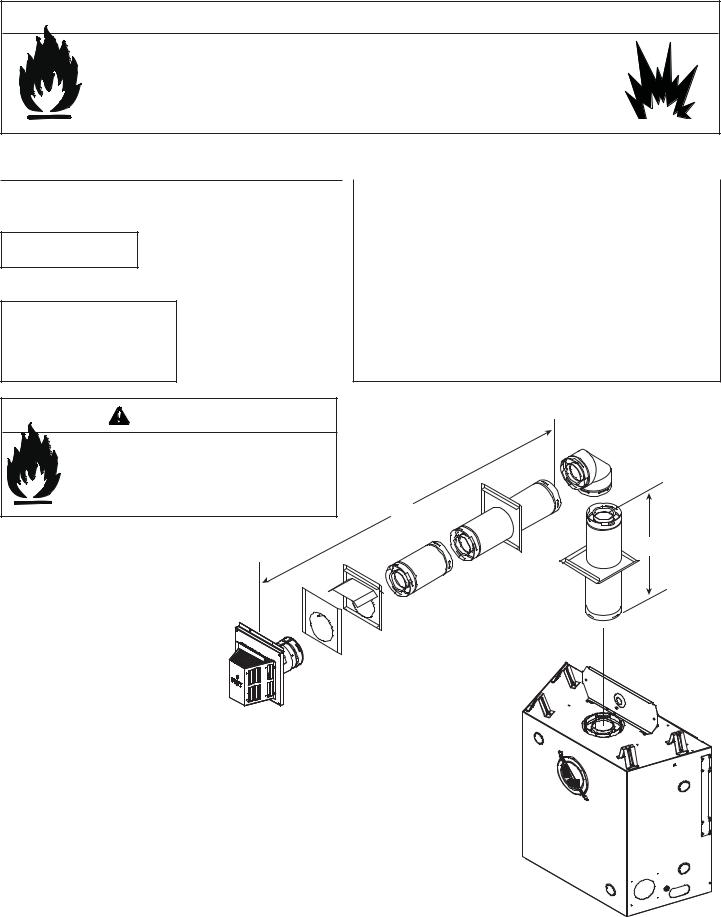
E. Vent Diagrams
 WARNING
Fire Risk. Explosion Risk.
Do NOT pack insulation or other combustibles between ceiling firestops.
•ALWAYS maintain specified clearances around venting and firestop systems.
•Install wall shield and ceiling firestops as specified.
Failure to keep insulation or other material away from vent pipe may cause fire.
1. Top Vent - Horizontal Termination Venting
One Elbow
Note: Use SL-D Series components only.
Note: There MUST be a 25% reduction in total H when using flex vent except when using the simple up and out installation (see Figure 5.3).
V Minimum |
|
H1 Maximum |
|
|||
SL-350TRS-D |
SL-550, SL-750TRS-E |
|||||
|
|
|||||
90º Elbow |
1-1/2 ft. |
457 mm |
1 ft. |
305 mm |
||
1/2 ft. |
152 mm |
2 ft. |
610 mm |
2 ft. |
610 mm |
|
1-1/2 ft. |
457 mm |
3 ft. |
914 mm |
3 ft. |
914 mm |
|
2-1/2 ft. |
762 mm |
5 ft. |
1-1/2 m |
5 ft. |
1-1/2 m |
|
3-1/2 ft. |
1.1 m |
7 ft. |
2.1 m |
7 ft. |
2.1 m |
|
4-1/2 ft. |
1.4 m |
15 ft. |
4.6 m |
15 ft. |
4.6 m |
|
H1 Maximum= 15 ft. (4.6 m)
V1 + H1 Maximum= 40 ft. (12.2 m)
WARNING
Fire Risk.
•When using SL-HRC-SS and SL-HRC-ZC-SS termination caps on top vented fireplaces, a one foot minimum vertical vent section is required before installing first elbow.
H1
V1
Figure 5.4
Heat & Glo • SL-750TRS-IPI-E, SL-550TRS-IPI-E, SL-350TRS-D, SL-350TRS-IPI • 2120-900 Rev. D • 6/07 |
15 |
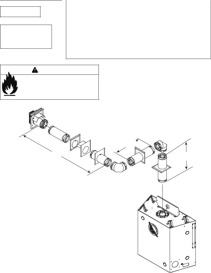
Two Elbows
Note: Use SL-D Series components only.
Note: There MUST be a 25% reduction in total H when using flex vent except when using the simple up and out installation (see Figure 5.3).
|
V Minimum |
|
H Maximum |
||
|
|
|
|
||
|
SL-350TRS-D, SL-550TRS-E, SL-750TRS-E |
||||
|
|
|
|||
|
90º Elbow |
|
NOT ALLOWED |
||
1/2 ft. |
|
152 mm |
1 ft. |
|
305 mm |
1-1/2 ft. |
|
457 mm |
2 ft. |
|
610 mm |
2-1/2 ft. |
|
762 mm |
4 ft. |
|
1.2 m |
3-1/2 ft. |
|
1.1 m |
6 ft |
|
1.8 m |
4-1/2 ft. |
|
1.4 m |
14 ft. |
|
4.3 m |
H1 + H2 Maximum= 14 ft. (4.3 m)
V1 + H1 + H2 Maximum= 40 ft. (12.2 m)
WARNING
Fire Risk.
•When using SL-HRC-SS and SL-HRC-ZC-SS termination caps on top vented fireplaces, a one
foot minimum vertical vent section is required before installing first elbow.
H1
H2 |
V1 |
|
Figure 5.5
16 |
Heat & Glo • SL-750TRS-IPI-E, SL-550TRS-IPI-E, SL-350TRS-D, SL-350TRS-IPI • 2120-900 Rev. D • 6/07 |
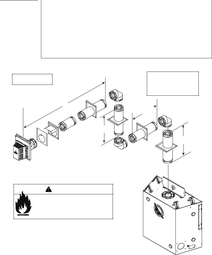
1. Top Vent - Horizontal Termination - (continued)
Three Elbows
V1 Minimum |
H1 Maximum |
H1 + H2 Maximum |
H1 Maximum |
H1 + H2 Maximum |
||||||
|
Model: SL-350TRS-D |
|
Models: SL-550TRS-IPI-E, SL-750TRS-IPI-E |
|||||||
|
|
|
|
|||||||
Elbow only |
1-1/2 ft. |
457 mm |
2 ft. |
|
610 mm |
1 ft. |
305 mm |
2 ft. |
610 mm |
|
|
|
|
|
|
|
|
|
|
|
|
1/2 ft. |
152 mm |
2 ft. |
610 mm |
4 ft. |
|
1.2 m |
2 ft. |
610 mm |
4 ft. |
1.2 m |
|
|
|
|
|
|
|
|
|
|
|
1-1/2 ft. |
457 mm |
3 ft. |
914 mm |
6 ft. |
|
1.8 m |
3 ft. |
914 mm |
6 ft. |
1.8 m |
2-1/2 ft. |
762 mm |
5 ft. |
1.5 m |
10 ft |
|
3.0 m |
5 ft. |
1.5 m |
10 ft. |
3.0 m |
3-1/2 ft. |
1.1 m |
7 ft. |
2.1 m |
14 ft. |
|
4.3 m |
7 ft. |
2.1 m |
14 ft. |
4.3 m |
|
|
|
|
|
|
|
|
|
|
|
4-1/2 ft. |
1.4 m |
14 ft. |
4.3 m |
14 ft. |
|
4.3 m |
14 ft. |
4.3 m |
14 ft. |
4.3 m |
|
|
|
|
|
|
|
|
|
|
|
V1 + H1 + V2 + H2 Maximum = 40 ft. (12.2 m)
Note: Use SL-D Series components only.
H2
V2
WARNING
Fire Risk.
•When using SL-HRC-SS and SL-HRC-ZC-SS termination caps on top vented fireplaces, a one foot minimum vertical vent section is required
before installing first elbow.
Note: There MUST be a 25% reduction in total H when using flex vent except when using the simple up and out installation (see Figure 5.3).
H1
V1
Figure 5.6
Heat & Glo • SL-750TRS-IPI-E, SL-550TRS-IPI-E, SL-350TRS-D, SL-350TRS-IPI • 2120-900 Rev. D • 6/07 |
17 |

2. Top Vent - Vertical Termination
No Elbow
Note: Use SL-D Series components only.
Note: If installing a vertical vent/termination off the top of the appliance, the optional vertical termination baffle may be needed.
V1 = 44 ft. Max. (13.4 m)
CAP 
V1
Figure 5.7
Exhaust restrictors are recommended for these vertically terminated products which have excessive draft. Exhaust restrictors will compensate for high draft, and restore visual flame height. If the vent configuration has a total vertical of 15-44 feet, an exhaust restrictor may be needed. The exhaust restrictor can be located in the appliance manual bag.
Exhaust restrictor Instructions
1.Install the exhaust restrictor over the center of the exhaust outlet in the firebox (see Figure 5.8).
2.Center the exhaust restrictor in the open end of the exhaust outlet and secure through the slots on the exhaust restrictor with the 2-1/4 in. self tapping screws provided in the appliance manual bag.
INNER HEAT SHIELD
To access the exhaust openings, remove the inner heat shield. To remove inner heat shield, remove the two screws.
Top Vent Application
Exhaust restrictor
Rear Vent Application
Exhaust restrictor
Note: Be sure to reinstall the inner heat shield after exhaust restrictor installation.
Figure 5.8
18 |
Heat & Glo • SL-750TRS-IPI-E, SL-550TRS-IPI-E, SL-350TRS-D, SL-350TRS-IPI • 2120-900 Rev. D • 6/07 |
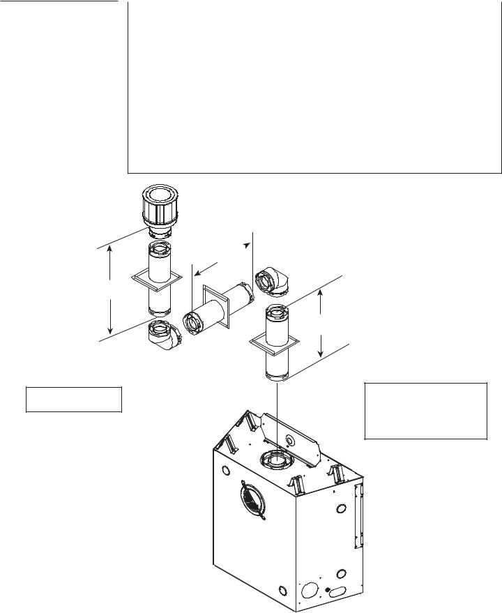
2. Top Vent - Vertical Termination - (continued)
Two 90º Elbows
V1 Minimum |
H1 Maximum |
H1 |
Maximum |
V2 |
V1 + V2 Minimum |
||||
SL-350TRS-D |
SL-550TRS-E, SL-750TRS-E |
* |
* |
||||||
|
|
||||||||
|
|
|
|
|
|
|
|
|
|
90º Elbow |
1-1/2 ft. |
457 mm |
1 ft. |
|
305 mm |
* |
* |
||
|
|
|
|
|
|
|
|
|
|
1/2 ft. |
152 mm |
2 ft. |
610 mm |
2 ft. |
|
610 mm |
* |
* |
|
1 ft. |
305 mm |
2-1/2 ft. |
762 mm |
2-1/2 ft. |
|
762 mm |
* |
* |
|
2 ft. |
610 mm |
4 ft. |
1.2 m |
4 ft. |
|
1.2 m |
* |
* |
|
|
|
|
|
|
|
|
|
|
|
3 ft. |
914 m |
6 ft. |
1.8 m |
6 ft. |
|
1.8 m |
* |
* |
|
4 ft. |
1.2 m |
8 ft. |
2.4 m |
8 ft. |
|
2.4 m |
* |
* |
|
5 ft. |
1.5 m |
15 ft. |
4.6 m |
15 ft |
|
4.6 m |
* |
* |
|
|
|
|
|
|
|
|
|
|
|
H1 Maximum= 15 ft. (4.6 m)
V1 + V2 + H Maximum = 40 ft. (12.2 m)
*No specific restrictions on this value EXCEPT V1 + V2 + H1 CANNOT exceed 40 ft. (12.2 m)
H1
V2
V1
Note: Use SL-D Series components only.
Note: There MUST be a 25% reduction in total H when using flex vent except when using the simple up and out installation (see Figure 5.3).
Figure 5.8
Heat & Glo • SL-750TRS-IPI-E, SL-550TRS-IPI-E, SL-350TRS-D, SL-350TRS-IPI • 2120-900 Rev. D • 6/07 |
19 |
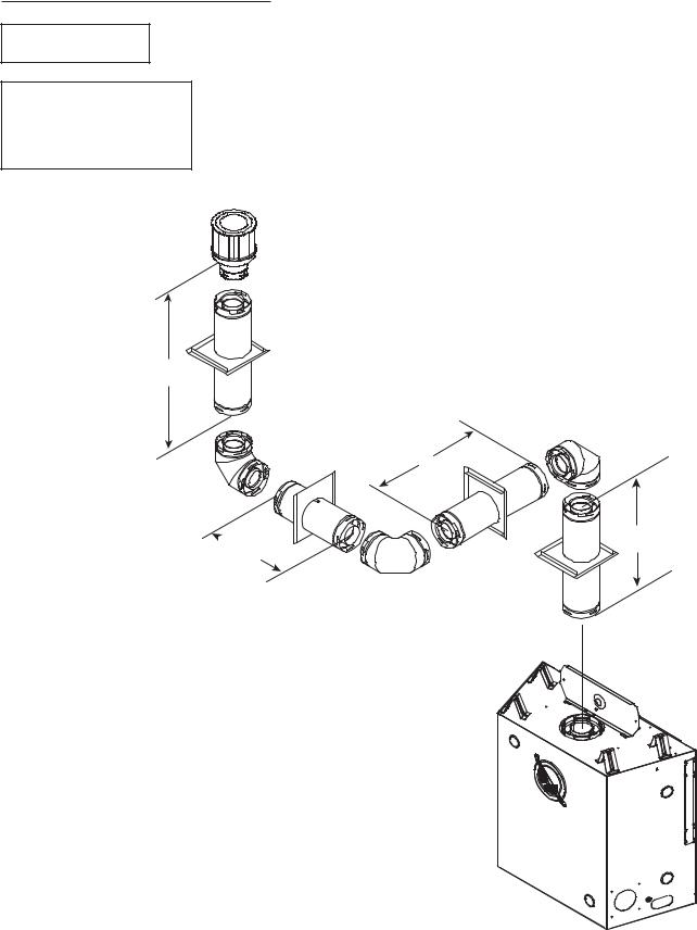
2. Top Vent - Vertical Termination - (continued)
Three 90º Elbows
Note: Use SL-D Series components only.
Note: There MUST be a 25% reduction in total H when using flex vent except when using the simple up and out installation (see Figure 5.3).
|
|
|
|
|
ALL MODELS |
|
|
|
|
|
|
|
|
|
|
|
|
|
|
|
|
|
|
|
|
V1 |
H1+ H2 Maximum |
|
V2 |
V1 + V2 Minimum |
|||||
|
90º Elbow |
0 |
0 |
1-1/2 ft. |
|
457 mm |
1-1/2 ft. |
|
457 mm |
||
Î |
1/2 ft.. |
|
152 mm |
1 ft. |
305 mm |
* |
|
* |
* |
|
* |
|
1-1/2 ft. |
|
457 mm |
2 ft. |
610 mm |
* |
|
* |
* |
|
* |
|
2-1/2 ft. |
|
762 mm |
4 ft. |
1.2 m |
* |
|
* |
* |
|
* |
|
3-1/2 ft. |
|
1.1 m |
6 ft. |
1.8 m |
* |
|
* |
* |
|
* |
|
|
|
|
|
|
|
|
|
|
|
|
|
4-1/2 ft. |
|
1.4 m |
14 ft. |
4.3 m |
* |
|
* |
* |
|
* |
|
|
|
|
|
|
|
|
|
|
|
|
|
|
|
|
H1 Maximum = 14 ft. (4.3 m) |
|
|
|
||||
|
|
*No specific restrictions on this value EXCEPT V1 + V2 + H1 + H2 |
|
||||||||
|
|
|
|
CANNOT exceed 40 ft. (12.2 m). |
|
|
|
||||
|
|
|
|
|
|
|
|
|
|
|
|
V2
H1
 H2 V1
H2 V1
Figure 5.9
20 |
Heat & Glo • SL-750TRS-IPI-E, SL-550TRS-IPI-E, SL-350TRS-D, SL-350TRS-IPI • 2120-900 Rev. D • 6/07 |
2. Top Vent - Vertical Termination - (continued)
Four 90º Elbows |
V1 Min. |
H1 Max. |
V2 Min. |
H2 Max. |
V3 Min. |
|
1-1/2 ft. 457 mm |
4 ft. 1.2 m |
4 ft. 1.2 m |
4 ft. 1.2 m |
3-1/2 ft. 1.0 m |
||
|
||||||
|
|
V1 + V2 + V3 + H1 + H2 Maximum= 40 ft. (12.2 m) |
|
|||
V3
V2
 H2
H2
Note: Use SL-D Series components only.
Note: There MUST be a 25% reduction in total H when using flex vent except when using the simple up and out installation (see Figure 5.3).
H1
V1
Figure 5.17
Heat & Glo • SL-750TRS-IPI-E, SL-550TRS-IPI-E, SL-350TRS-D, SL-350TRS-IPI • 2120-900 Rev. D • 6/07 |
21 |
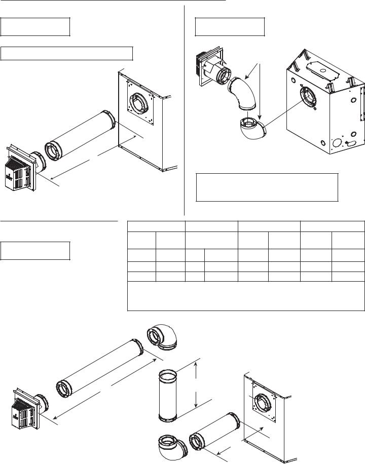
3. Rear Vent - Horizontal Termination
No Elbow |
Two 90º Elbows |
Note: Use DVP Series |
Note: Use DVP Series |
components only. |
components only. |
H1 = 24 in. (610 mm) Maximum |
90-DEGREE ELBOWS |
H1
|
|
|
|
Use two 90º elbows for corner installations. |
|
|||
|
|
|
|
The use of two 90º elbows in a corner installation |
|
|||
|
|
|
|
will affect space requirements. |
|
|
||
Figure 5.10 |
|
|
Figure 5.11 |
|
|
|
|
|
Two 90º Elbows |
H1 Maximum |
V1 Minimum |
|
H2 |
H1 + H2 Maximum |
|||
|
|
Back to Back |
|
|
|
|
||
|
1-1/2 ft. |
457 mm |
1 ft. |
305 mm |
2-1/2 ft. |
762 mm |
||
Note: Use DVP Series |
|
Elbows |
||||||
|
|
|
|
|
|
|
||
|
|
|
|
|
|
|
|
|
components only. |
3-1/2 ft. |
1.1 m |
1 ft. |
305 mm |
3 ft. |
914 mm |
6-1/2 ft. |
2.0 m |
|
5-1/2 ft. |
1.7 m |
2 ft. |
610 mm |
5 ft. |
1.5 m |
10-1/2 ft. |
3.2 m |
|
7-1/2 ft. |
2.3 m |
3 ft. |
914 mm |
6-1/2 ft. |
2.1 m |
14 ft. |
4.3 m |
|
|
|
|
H1 Maximum = 7-1/2 ft. (2.3 m) |
|
|
||
|
|
|
|
H1 + H2 Maximum = 14 ft. (4.3 m) |
|
|
||
|
|
|
|
V1 + H1 + H2= 40 ft. (12.2 m) |
|
|
||
H2 |
V1 |
H1
Figure 5.12
22 |
Heat & Glo • SL-750TRS-IPI-E, SL-550TRS-IPI-E, SL-350TRS-D, SL-350TRS-IPI • 2120-900 Rev. D • 6/07 |
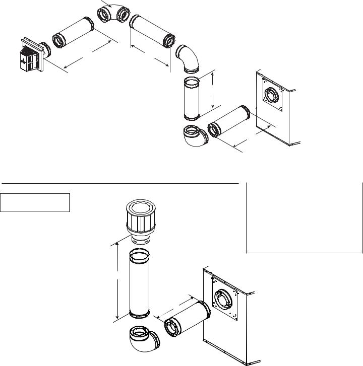
3. Rear Vent - Horizontal Termination - (continued)
Three Elbows
|
|
|
|
H1 Maximum |
V1 Minimum |
|
H2+ H3 |
|
H1+ H2+ H3 Maximum |
|||||
Note: Use DVP Series |
|
|
|
1-1/2 ft. |
457 mm |
Back to Back |
1 ft. |
|
305 mm |
|
2-1/2 ft. |
762 mm |
||
components only. |
|
|
|
|
Elbows |
|
|
|||||||
|
|
|
|
|
|
|
|
|
|
|
|
|||
|
|
|
|
|
|
|
|
|
|
|
|
|
|
|
|
|
|
|
3-1/2 ft. |
1.1 m |
1 ft. |
|
305 mm |
2 ft. |
|
610 mm |
|
5-1/2 ft. |
1.7 m |
|
|
|
|
5-1/2 ft. |
1.7 m |
2 ft. |
|
610 mm |
4 ft. |
|
1.2 m |
|
9-1/2 ft. |
2.9 m |
|
|
|
|
7-1/2 ft. |
2.3 m |
3 ft. |
|
914 mm |
6 ft. |
|
1.8 m |
|
13-1/2 |
4.1 m |
|
|
|
|
|
|
|
ft. |
|||||||
|
|
|
|
|
|
|
|
|
|
|
|
|
|
|
|
|
INSTALLED |
|
|
H1 Maximum = 7-1/2 ft. (2.3 m) |
|
|
|||||||
|
|
|
|
H1 + H2 + H3 Maximum =13-1/2 ft. (4.1 m) |
|
|
||||||||
|
HORIZONTALLY |
|
|
|
|
|||||||||
|
|
|
|
|
|
|
V1 + H1 + H3= 40 ft. (12.2 m) |
|
|
|||||
H3 |
H2 |
V1
Figure 5.13
H1
4. Rear Vent - Vertical Termination
One Elbow
Note: Use DVP Series components only.
V1 Minimum |
H1 Maximum |
||
Elbow Only |
1-1/2 ft. |
457 mm |
|
1 ft. |
305 mm |
3-1/2 ft. |
1.1 m |
2 ft. |
610 mm |
5-1/2 ft. |
1.7 m |
3 ft. |
914 mm |
7-1/2 ft. |
2.3 m |
H1 Maximum = 7-1/2 ft. (2.3 m) V1 + H1 Maximum = 40 ft. (12.2 m)
V1
H1
Figure 5.14
Heat & Glo • SL-750TRS-IPI-E, SL-550TRS-IPI-E, SL-350TRS-D, SL-350TRS-IPI • 2120-900 Rev. D • 6/07 |
23 |
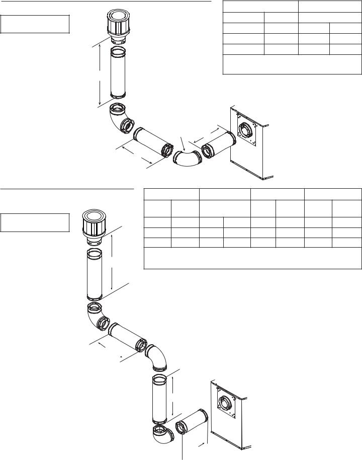
4. Rear Vent - Vertical Termination |
- (continued) |
|
|
|
Two Elbows |
|
|
|
|
|
H1+ H2 Maximum |
V1 Minimum |
||
Note: Use DVP Series |
1/2 ft. |
152 mm |
Back to Back Elbows |
|
|
|
|
|
|
components only. |
2-1/2 ft. |
762 mm |
1 ft. |
305 mm |
|
4-1/2 ft. |
1.4 m |
2 ft. |
610 mm |
|
6-1/2 ft. |
2.0 m |
3 ft. |
914 mm |
|
|
H Maximum = 6-1/2 ft. (2 m) |
|
|
V1 |
V1 + H1 + H2 Maximum = 40 ft. (12.2 m) |
|||
|
|
|
|
|
INSTALLED
|
HORIZONTALLY |
H1 |
|
|
|
|
|
||
|
|
|
|
|
|
|
|||
|
H2 |
|
|
|
|
|
|
|
|
Figure 5.15 |
|
|
|
|
|
|
|
|
|
Three Elbows |
H1 Maximum |
V1 Minimum |
|
H2 |
H1 + H2 |
Maximum |
|||
|
1-1/2 ft. |
457 mm |
Back to Back |
1 ft. |
305 mm |
2-1/2 ft. |
762 mm |
||
|
Elbows |
||||||||
Note: Use DVP Series |
|
|
|
|
|
|
|||
3-1/2 ft. |
1.1 m |
1 ft. |
305 mm |
3 ft. |
914 mm |
6-1/2 ft. |
2.0 m |
||
components only. |
|||||||||
5-1/2 ft. |
1.2 m |
2 ft. |
610 mm |
5 ft. |
1.5 m |
10-1/2 ft. |
3.2 m |
||
|
|||||||||
|
7-1/2 ft. |
2.3 m |
3 ft. |
914 mm |
7 ft. |
2.1 m |
14-1/2ft. |
4.4 m |
|
|
V2 |
|
H1 Maximum = 7-1/2 ft. (2.3 m) |
|
|
||||
|
V1 + V2 + H1 + H2 Maximum = 40 ft. (12.2 m) |
|
|||||||
H2 
V1
 H1
H1
Figure 5.16
24 |
Heat & Glo • SL-750TRS-IPI-E, SL-550TRS-IPI-E, SL-350TRS-D, SL-350TRS-IPI • 2120-900 Rev. D • 6/07 |
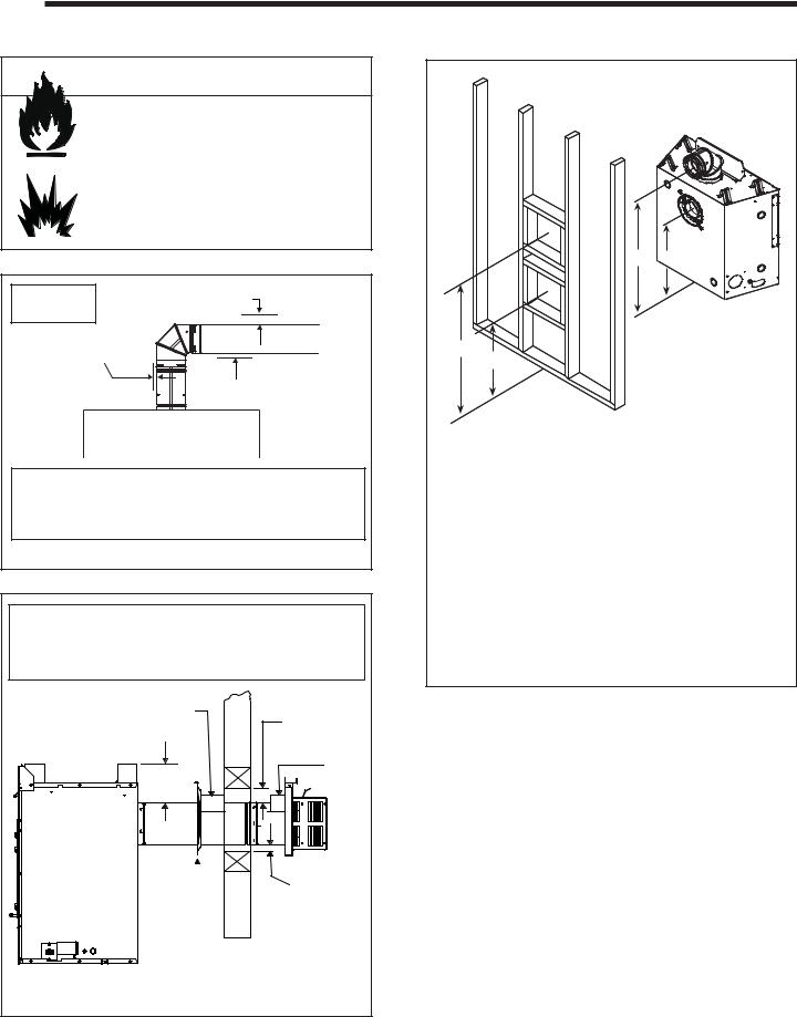
6 Vent Clearances and Framing
A. Pipe Clearances to Combustibles |
B. Wall Penetration Framing |
 WARNING
Fire Risk. Explosion Risk.
Maintain vent clearance to combustibles as specified.
•Do not pack air space with insulation or other materials.
Failure to keep insulation or other materials away from vent pipe may cause fire.
3 in. TOP Note: Slope CLEARANCE
not required.
1 in. CLEARANCE AROUND VERTICAL SECTIONS
1 in. SIDE AND BOTTOM CLEARANCE
Note: When using SL pipe, minimum clearances from the vent pipe to combustible materials at wall firestops are:
Top: 2-1/2 inches Bottom: 1/2 inch Sides: 1 inch
Figure 6.1 Pipe Clearances
Note: Heat shields MUST overlap by a minimum of 1-1/2 in. (38 mm). The heat shield is designed to be used on a wall 4 in. to 7-1/4 in. (102 mm to 184 mm) thick. If wall thickness is less than 4 in. (102 mm) the existing heat shields must be field trimmed. If wall thickness is greater than 7-1/4 in. (184 mm) a DVP-HSM-B will be required.
HEAT
SHIELD 3 in. TOP
CLEARANCE
HEAT SHIELD
7 in.
|
|
1 in. CLEARANCE |
|
WALL |
|||
BOTTOM & SIDES |
|||
SHIELD |
|||
|
|||
FIRESTOP |
|
||
|
|
WALL |
|
Figure 6.2 DVP Horizontal Venting Clearances to Combustible Materials
C D
A*
B*
|
|
A* |
B* |
C |
D |
|
SL-750TRS-IPI-E |
Inches |
41 |
27-7/8 |
40 |
26-7/8 |
|
Millimeters |
1041 |
708 |
1016 |
683 |
||
|
||||||
SL-550TRS-IPI-E |
Inches |
36-1/2 |
24-3/8 |
35-1/2 |
23-3/8 |
|
Millimeters |
927 |
619 |
902 |
594 |
||
|
||||||
SL-350TRS-D |
Inches |
35-1/2 |
22-3/8 |
34-1/2 |
21-3/8 |
|
Millimeters |
902 |
568 |
876 |
543 |
||
|
*Shows center of vent framing hole for top or rear venting. The center of the hole is one (1) inch (25.4 mm) above the center of the horizontal vent pipe.
Figure 6.3 Exterior Wall Hole
Combustible Wall Penetration
Frame a hole in a combustible wall for an interior wall shield firestop, (Figure 6.2) whenever a wall is penetrated. Use same size framing materials as those used in the wall construction. The wall shield firestop maintains minimum clearances and prevents cold air infiltration.
Non-Combustible Wall Penetration
If the hole being penetrated is surrounded by noncombustible materials such as concrete, a hole with diameter one inch greater than the pipe is acceptable.
Heat & Glo • SL-750TRS-IPI-E, SL-550TRS-IPI-E, SL-350TRS-D, SL-350TRS-IPI • 2120-900 Rev. D • 6/07 |
25 |
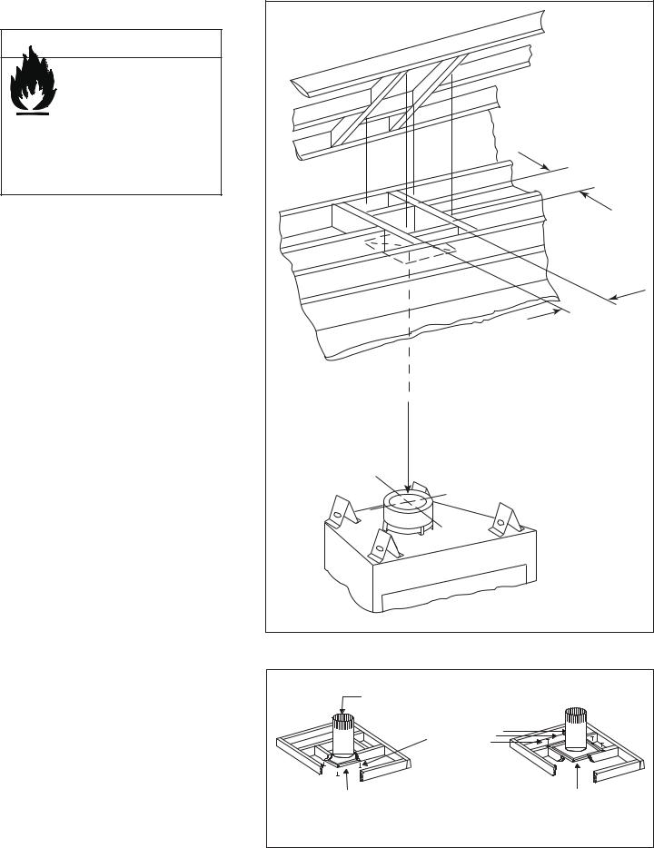
C. Vertical Penetration Framing
 WARNING
Fire Hazard
Keep loose materials or blown insulation from touching the vent pipe.
•National building codes recommend using attic shield to keep loose materials/ blown insulation from contacting vent.
•Hearth & Home Technologies requires the use of an attic shield.
Installing the Ceiling Firestop
•Frame an opening 10 inches by 10 inches whenever the vent system penetrates a ceiling/floor (see Figure 6.4).
•Frame the area with the same sized lumber as used in ceiling/floor joist.
•When installing a top vent vertical termination appliance the hole should be directly above the appliance, unless the flue is offset.
•Do not pack insulation around the vent. Insulation must be kept away from the pipe.
Installing Attic Shield
Note: An additional ceiling firestop is not required if attic shield is used.
•Frame opening for attic shield.
•Attic shield may be installed above or below ceiling (see Figure 6.5).
•Secure with three fasteners on each side.
•Fold tabs at top of attic shield in toward vent pipe. Tabs must keep vent pipe centered within shield.
•Field construct additional shield height if insulation is deeper than height of attic shield.
ATTIC ABOVE |
10 IN. (254 MM) |
10 IN. |
(254 MM) |
HOLE SHOULD MEASURE |
10 IN. X 10 IN. |
(254 MM X 254 MM) |
INSIDE TO INSIDE |
Figure 6.4 |
BEND TABS IN |
|
AROUND PIPE |
|
3 FASTENERS |
|
PER SIDE |
|
ATTIC SHIELD INSTALLED |
ATTIC SHIELD INSTALLED |
BELOW CEILING |
ABOVE CEILING |
Figure 6.5 Installing the Attic Shield |
|
26 |
Heat & Glo • SL-750TRS-IPI-E, SL-550TRS-IPI-E, SL-350TRS-D, SL-350TRS-IPI • 2120-900 Rev. D • 6/07 |
 Loading...