


 Loading...
INSTALLATION & OPERATING
INSTRUCTIONS
E36 E39 E42
WOODBURNING FIREPLACE
Note: An arrow ( ) found in the text signifies change in content.
WARNING!
Improper installation, adjustment, alteration, service or maintenance can cause injury or property damage. Refer to this manual. For assistance or additional information, consult a qualified installer, service agency or the gas supplier.
08/04 |
17335 Rev L |
1 |

E36/39/42 INSTALLATION INSTRUCTIONS
|
Table of Contents |
|
|
Design and Installation Considerations........................................................................................... |
3 |
A. Listings and CodeApprovals .......................................................................................................... |
4 |
|
B. Description of the Fireplace System .............................................................................................. |
4 |
|
C. Fireplace System Components ...................................................................................................... |
5 |
|
D. |
Pre-Installation Preparation .......................................................................................................... |
10 |
E. |
Chimney Requirements................................................................................................................ |
12 |
F. |
Installation of Fireplace ................................................................................................................ |
15 |
G. |
Constructing a Chase .................................................................................................................. |
22 |
H. |
Operating Instructions.................................................................................................................. |
25 |
I. |
Maintenance Instructions ............................................................................................................. |
29 |
|
Index ........................................................................................................................................... |
31 |
|
Warranty ...................................................................................................................................... |
32 |
CAUTION:
Do not expose the fireplace to the elements (i.e. rain, etc.) and keep the fireplace dry at all times. Wet insulation will produce an odor when the fireplace is used.
WARNING!
This fireplace is tested and listed for use only with the optional accessories listed in these instructions. Use of optional accessories not specifically tested for this appliance could void the warranty and/or result in a safety hazard.
Safety Precautions
1.Please read these installation instructions completely before beginning installation procedures. Failure to follow them could cause a fireplace malfunction resulting in serious injury and/or property damage.
2.Always check your local building codes prior to installation. The installation must comply with all local, regional, state and national codes and regulations.
3.An adequate supply of replacement combustion air from outside the house must be available to the fire for the fireplace to operate properly. To achieve this, the use of the optional outside air kit is highly recommended.
In the event the home is unusually tightly sealed, the optional combustion air kit may not provide all the air required to support combustion. Hearth & Home Technologies is not responsible for any smoking or related problems that may result from the lack of adequate combustion air. It is the responsibility of the builder/contractor to ensure that adequate combustion air has been provided for the fireplace.
4.The fireplace must be installed with the Hearth & Home Technologies SL Series Chimney System.
The chimney system must always terminate outside the building. Be sure to follow all chimney specifications given in these installation instructions.
5.NEVER leave children unattended when there is a fire burning in the fireplace.
6.This fireplace is built for solid fuel only. NEVER use gasoline, gasoline type lantern fuel, kerosene, charcoal light fluid, or similar liquids in this fireplace. Keep any flammable liquids a safe distance from the fireplace.
7.DO NOT use chimney cleaners or flame colorants in your fireplace.
8.The flue damper must be open at all times when the fireplace is in use.
9.While servicing this fireplace, always shut off any electricity or gas to the fireplace. This will prevent possible electric shock or burns. Also, make sure the fireplace is completely cooled before servicing.
10.To ensure a safe fireplace system and to prevent the build up of soot and creosote, inspect and clean the fireplace and chimney prior to use and periodically during the burning season. See “Maintenance Instructions” in this manual for cleaning instructions.
2 |
17335 Rev L |
07/04 |
E36/39/42 INSTALLATION INSTRUCTIONS
DESIGN AND INSTALLATION CONSIDERATIONS
When selecting a location for your woodburning fireplace, it is important to evaluate a number of considerations. Modern construction techniques can create conditions that may not allow your chimney to draft properly. This may result in smoke spillage from your fireplace, as well as cause other combustion appliances to operate incorrectly.
Tightly sealed construction is important for energy efficiency. Unfortunately, a great deal of effort has been directed to tightening up sidewall construction, while considerably less attention has been paid to tightening upper portions of the warm air envelope (insulated ceilings). This has increased the “Stack Effect”, a condition that increases the negative pressure generated by the structure. This negative pressure will directly affect the drafting performance of a fireplace chimney. To minimize the negative pressure generated by stack effect, make certain that all duct work installed in the attic spaces is sealed airtight. Minimize the number of recessed light fixtures installed in the insulated ceiling, and use sealed recessed light fixtures. Finally, make certain the whole house fans and attic access panels are tightly sealed. These are important design considerations that must be observed during the design and construction stage of the home.
If you desire to put a fireplace in your basement, we recommend that you consider a direct vent gas fireplace. Basements always have a significant negative air pressure that causes the fireplace system to be more susceptible to smoke spillage and cold flue back drafting. Since direct vent gas fireplaces are sealed, they are not affected by the negative pressure that exists in basements.
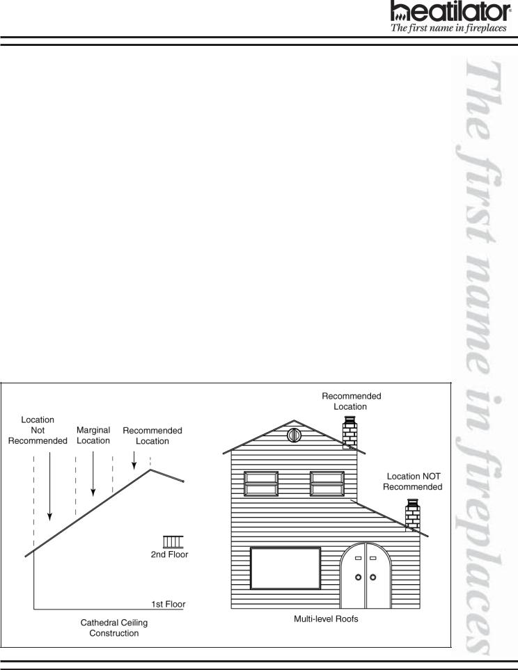
Finally, woodburning fireplaces perform best when their chimney (roof termination) is located on the upper half of the roof, especially when cathedral ceilings are present. Chimneys that are located on the lower half of the roof realize what is known as “lazy flue” and will not draft as well as a chimney that is located in the upper portion of the roof. The reason for this is that the stack effect generated by the overall height of the living spaces inside the house will exceed the draft generated by the chimney system. If you desire to place a woodburning fireplace in a location where the termination cap would be located on the lower half of a roof, such as on an outside wall at the base of a cathedral ceiling, we recommend that you consider using a direct vent gas fireplace. This will assure the homeowner a fireplace that operates correctly.
These properties do not affect just your woodburning factory built fireplace. They can cause any woodburning fireplace as well as any conventionally vented (B-vent) gas appliance to operate improperly. Careful planning at this stage of your project will ensure satisfaction with the operation of your fireplace once it is completed.
08/04 |
17335 Rev L |
3 |
E36/39/42 INSTALLATION INSTRUCTIONS
A. LISTINGS AND CODE APPROVALS
This fireplace system has been tested and listed in accordance with UL 127 and ULC-S610 standards, and has been listed by Underwriters Laboratories Inc. for installation and operation in the United States and Canada as described in this manual.
This fireplace has been tested and listed for use with the optional components listed on page 5. These optional components may be purchased separately and installed at a later date. However, installation of an outside air kit will require significant reconstruction, and should be installed at the time of the initial fireplace installation.
Check with your local building code agency prior to installing this fireplace to ensure compliance with local codes, including the need for permits and follow-up inspections. If you need assistance during installation, please contact your local dealer or the Heatilator Technical Services Department, Hearth & Home Technologies Inc., 1915 W. Saunders St., Mt. Pleasant, Iowa 52641 (1-800-927-6841).
Heatilator® is a registered trademark of Hearth & Home Technologies Inc.
WARNING!
This fireplace and its components are designed to be installed and operated as a system. Any alteration to or substitution for items in this system, unless allowed by these installation instructions, will void the Underwriters Laboratories listing and may void the product warranty. It may also create a hazardous installation. Read through these instructions thoroughly before starting your installation and follow them carefully throughout your project.
B.DESCRIPTION OF THE FIREPLACE SYSTEM
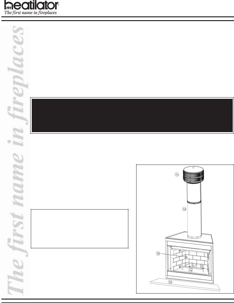
1.The Heatilator fireplace system consists of the following:
a.Fireplace/Integral Grate
b.Refractory
c.Chimney Termination Cap
d.Chimney System
e.Hearth Extension
2.Optional Components Include:
a.Glass Doors
b.Chimney Air Kit
c.Outside Combustion Air System
Note: Illustrations used throughout these instructions reflect “typical installations” and are for design purposes only. Actual installation may vary slightly due to individual design preferences. However, minimum and maximum clearances must be maintained at all times.
The illustrations and diagrams used throughout these installation instructions are not drawn to scale.
Figure 1 - Typical Fireplace System
4 |
17335 Rev L |
07/04 |
E36/39/42 INSTALLATION INSTRUCTIONS
C.SYSTEM COMPONENTS
1.Fireplace Components
|
Catalog # |
|
Description: |
|
|
|
|
E36 |
E39 |
E42 |
Fireplace, includes integral grate and hearth protection strips |
HX3 |
HX3 |
HX4 |
Hearth Extension |
|
|
|
|
DM1036 |
DM1039 |
DM1042 |
Original Bifold Glass Doors - Black Finish |
|
|
|
|
DM1036B |
DM1039B |
DM1042B |
Original Bifold Glass Doors - Polished Brass Finish |
|
|
|
|
DM1036S |
DM1039S |
DM1042S |
Original Bifold Glass Doors - Stainless Steel Finish |
DP1036 |
none |
DP1042 |
Perception Glass Doors - Black Finish |
DP1036B |
none |
DP1042B |
Perception Glass Doors - Polished Brass Finish |
DP1036S |
none |
DP1042S |
Perception Glass Doors - Stainless Steel Finish |
DMA1036B |
none |
DMA1042B |
Arched Cabinet Style Glass Doors - Polished Brass Finish |
GR4 |
GR5 |
GR6 |
Integral Grate (included with fireplace) |
|
|
|
|
|
AK14 |
|
Outside Air Kit |
|
|
|
|
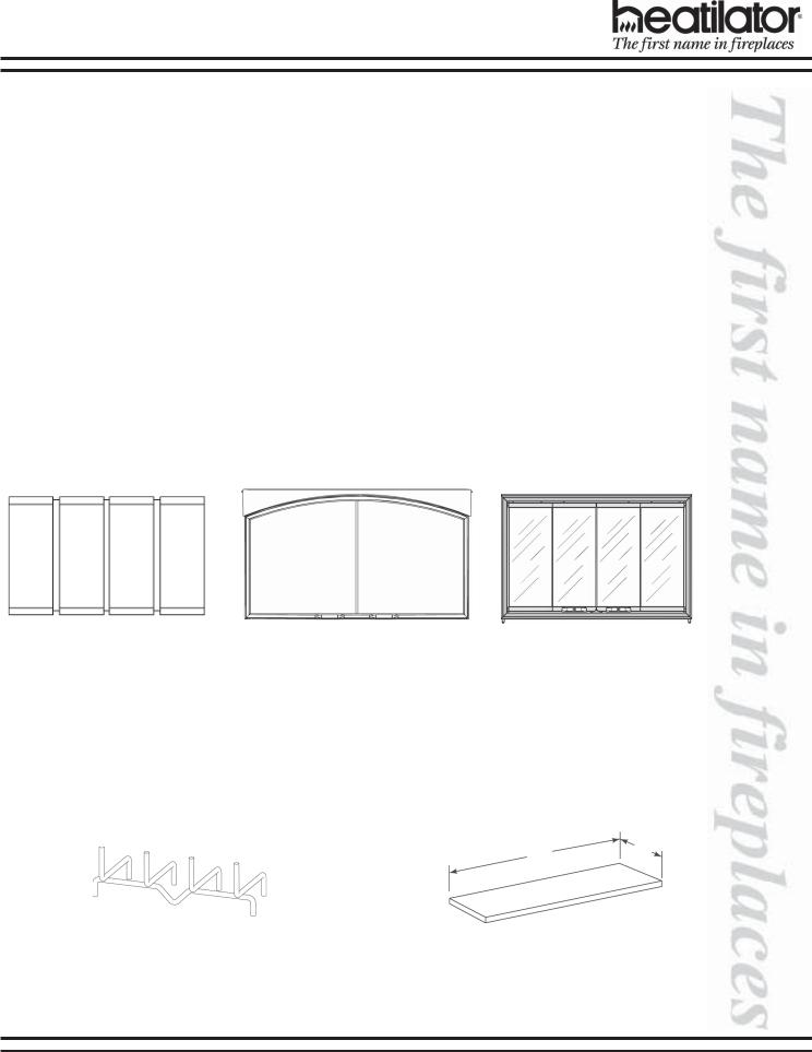
GLASS DOORS
DM1036 |
DM1036B |
DM1036S |
DMA1036B |
DP1036 |
DP1036B |
DP1036S |
DM1039 |
DM1039B |
DM1039S |
DMA1042B |
DP1042 |
DP1042B |
DP1042S |
DM1042 |
DM1042B |
DM1042S |
Arched Cabinet Glass Doors |
Perception Glass Doors |
||
Bifold Glass Doors
INTEGRAL GRATE |
HEARTH EXTENSION |
|
(Supplied) |
|
|
|
A |
B |
|
|
GR4
GR5 |
Cat # |
A |
B |
|
GR6 |
|
|
|
|
HX3 |
52 in. |
16 in. |
||
|
||||
|
|
|
|
|
|
HX4 |
66 in. |
20 in. |
|
|
|
|
|
08/04 |
17335 Rev L |
5 |
E36/39/42 INSTALLATION INSTRUCTIONS
Cat # |
A |
B |
C |
D |
|
|
|
|
|
|
|
E/EC36 |
36 in. |
41 in. |
25-1/4 in. |
12-5/8 in. |
|
914 mm |
1041 mm |
641 mm |
321 mm |
||
|
|||||
|
|
|
|
|
|
E/EC39 |
39 in |
44 in. |
28-1/4 in. |
14-1/8 in. |
|
991 mm |
1118 mm |
718 mm |
359 mm |
||
|
|||||
|
|
|
|
|
|
E/EC42 |
42 in. |
47 in. |
31-1/4 in. |
15-5/8 in. |
|
1067 mm |
1194 mm |
794 mm |
397 mm |
||
|
|||||
|
|
|
|
|
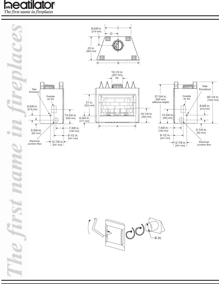
Fireplace Dimensions
OUTSIDE AIR KIT
AK14
6 |
17335 Rev L |
07/04 |
E36/39/42 INSTALLATION INSTRUCTIONS
2. Chimney Components
The following pictures show only those chimney components which may be safely used with this fireplace.
Catalog # |
Description: |
|
|
CAK4A |
Chimney Air Kit |
|
|
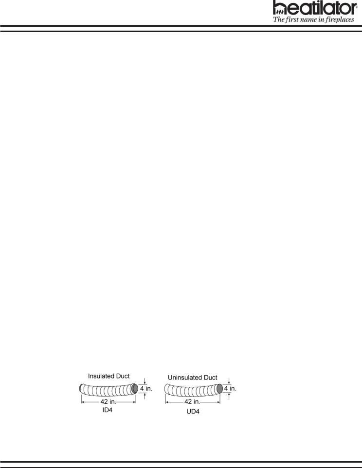
ID4 |
Insulated Duct/Outside Air |
|
|
UD4 |
Uninsulated Duct/Outside Air |
|
|
SL306 |
Chimney Section - 6 in. long |
|
|
SL312 |
Chimney Section - 12 in. long |
|
|
SL318 |
Chimney Section - 18 in. long |
|
|
SL324 |
Chimney Section - 24 in. long |
|
|
SL336 |
Chimney Section - 36 in. long |
|
|
SL348 |
Chimney Section - 48 in. long |
|
|
SL3 |
Chimney Stabilizer |
|
|
SL315 |
Chimney Offset/Return - 15-degree |
|
|
SL330 |
Chimney Offset/Return - 30-degree |
|
|
FS338 |
Firestop - Straight |
|
|
FS339 |
Firestop - 15-degree |
|
|
FS340 |
Firestop - 30-degree |
|
|
AS8 |
SL300 Straight Attic Insulation Shield, 24 in. |
|
|
JB877 |
Chimney Joint Band |
|
|
CB876 |
Chimney Bracket |
|
|
RF370 |
Roof Flashing - Flat to 6/12 Pitch |
|
|
RF371 |
Roof Flashing - 6/12 to 12/12 Pitch |
|
|
TR344 |
Round Termination Cap |
|
|
TR342 |
Round Telescoping Termination Cap |
|
|
ST375 |
Square Termination Cap |
|
|
TS345 |
Square Termination Cap |
|
|
TS345P |
Square Termination Cap - Painted |
|
|
TCT375 |
Terra Cotta Termination Cap |
|
|
CT35 |
Chase Top |
|
|
LDS33 |
Decorative Shroud - 3 ft x 3 ft |
|
|
LDS46 |
Decorative Shroud - 4 ft x 6 ft |
|
|
08/04 |
17335 Rev L |
7 |
E36/39/42 INSTALLATION INSTRUCTIONS
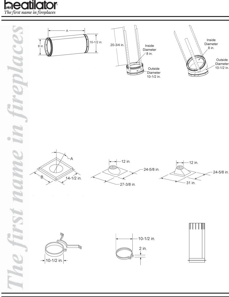
Chimney Sections
Catalog # |
A |
B |
SL306 |
6 in. |
4-3/4 in. |
|
|
|
SL312 |
12 in. |
10-3/4 in. |
|
|
|
SL318 |
18 in. |
16-3/4 in. |
|
|
|
SL324 |
24 in. |
22-3/4 in. |
|
|
|
SL336 |
36 in. |
34-3/4 in. |
|
|
|
SL348 |
48 in. |
46-3/4 in. |
|
|
|
A = Actual length
B = Effective length (length of chimney part after it has been snapped to another)
Firestop Spacer
Catalog # |
A |
B |
FS338 |
0-deg. |
14-1/2 in. |
|
|
|
FS339 |
15-deg. |
18-3/8 in. |
|
|
|
FS340 |
30-deg. |
23 in. |
CB876
Chimney Bracket
SL3 - Chimney Stabilizer |
SL330 - Offset/Return |
RF370 - Roof Flashing |
RF371 - Roof Flashing |
Flat to 6/12 Pitch |
6/12 to 12/12 Pitch |
JB877 |
AS8 |
Joint Band |
Straight Attic |
|
Insulation Shield |
8 |
17335 Rev L |
07/04 |

E36/39/42 INSTALLATION INSTRUCTIONS
ST375
Square LDS33 (3 ft x 3 ft) Termination Cap LDS46 (4 ft x 6 ft)
Decorative Shroud
TS345/TS345P
Square
Termination Cap
TR344
Round
Termination Cap
TR342
Round Telescoping
Termination Cap
CT35
Chase Top
CAK4A
Chimney Air Kit
08/04 |
17335 Rev L |
9 |
E36/39/42 INSTALLATION INSTRUCTIONS
D.PRE-INSTALLATION PREPARATION
1.Fireplace Locations and Space Requirements
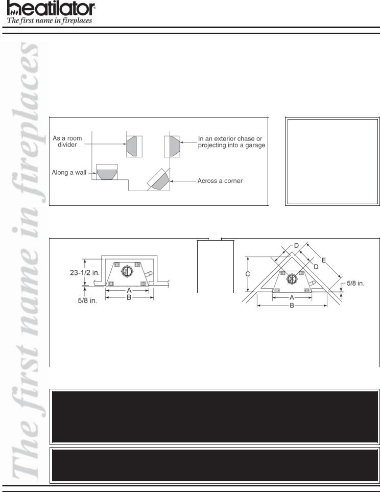
Several options are available to you when choosing a location for your fireplace. This fireplace may be used as a room divider, installed along a wall, across a corner or used in an exterior chase. See Figure 2.
Locating the fireplace in a basement, near frequently opened doors, central heat outlets or returns, or other locations of considerable air movement can affect the performance and cause intermittent smoke spillage from the front of the fireplace. Consideration should be given to these factors before deciding on a location.
CLEARANCES!
A minimum 1/2 in. air clearance must be maintained at the back and sides of the fireplace assembly.
Chimney sections at any level require a 2 in. minimum air space clearance between the framing and chimney section.
Figure 2 - Fireplace Locations
Figures 3 and 4 show two typical installations assuming an outside air kit is being used. Therefore, an allowance must be made for 90-deg bends. Less space is required when ducting goes directly outside without forming elbows.
These are rough framing dimensions only.
|
|
|
|
|
|
|
|
|
|
|
|
|
|
|
|
|
Cat # |
|
A |
B |
|
|
|
Cat # |
A |
B |
C |
|
D |
E |
|
|
|
|
|
|
|
|
|
|
|||||||
|
|
|
|
|
|
|
|
|
|
|
|
|
|
|
|
|
E/EC36 |
|
42 in |
45 in. |
|
|
|
E/EC36 |
42 in. |
72-3/4 in. |
36-3/8 in. |
|
15-5/8 in. |
51-3/8 in. |
|
|
|
1067 mm |
1143 mm |
|
|
|
|
|
|
|
|
|
|||
|
|
|
|
|
|
1067 mm |
1848 mm |
924 mm |
|
397 mm |
1305 mm |
||||
|
|
|
|
|
|
|
|
|
|
|
|
|
|
|
|
|
E/EC39 |
|
45 in. |
48 in. |
|
|
|
E/EC39 |
45 in. |
75-3/4 in. |
37-7/8 in. |
|
16-5/8 in. |
53-1/2 in. |
|
|
|
1143 mm |
1219 mm |
|
|
|
1143mm |
1924 mm |
962 mm |
|
422 mm |
1359 mm |
|||
|
|
|
|
|
|
|
|
|
|||||||
|
|
|
|
|
|
|
|
|
|
|
|
|
|
|
|
|
E/EC42 |
|
48 in. |
51 in. |
|
|
|
E/EC42 |
48 in. |
78-3/4 in. |
39-3/8 in. |
|
17-5/8 in. |
55-3/8 in. |
|
|
|
1219 mm |
1295 mm |
|
|
|
1219 mm |
2000 mm |
1000 mm |
|
448 mm |
1407 mm |
|||
|
|
|
|
|
|
|
|
|
|
|
|
|
|
|
|
|
|
Figure 3 |
|
|
|
|
|
|
|
Figure 4 |
|
|
|||
Installation Along a Wall or an Exterior Chase |
|
|
|
Corner Installation |
|
|
|||||||||
WARNING!
Do not draw outside air from garage spaces. Exhaust products of gasoline engines are hazardous.
Do not install outside air ducts such that the air may be drawn from attic spaces, basements or above the roofing where other heating appliances or fans and chimneys exhaust or utilize air. These precautions will reduce the possibility of fireplace smoking or air flow reversal.
WARNING!
To prevent contact with sagging or loose insulation, the fireplace must not be installed against vapor barriers or exposed insulation. Localized overheating could occur and a fire could result.
10 |
17335 Rev L |
07/04 |
Loading...