


 Loading...
Operating Instructions
Original Operating Instructions
spectrum D
Table of Contents |
|
|
Safety Instructions ................................................................................................................................... |
|
3 |
Intended Use.................................................................................................................................... |
|
3 |
Safety Instructions for Installation and Operation |
............................................................................... 3 |
|
FCC Notes ....................................................................................................................................... |
|
4 |
Modification of Equipment..................................................................................................... |
4 |
|
RF Exposure Statement ........................................................................................................ |
4 |
|
Operation ................................................................................................................................................. |
|
5 |
Activating the Transmitter ................................................................................................................. |
5 |
|
Deactivating the Transmitter ............................................................................................................. |
6 |
|
Automatic Power Off (APO) Function................................................................................................. |
6 |
|
Display ............................................................................................................................................ |
|
7 |
Battery and Battery Charger |
..................................................................................................................... |
8 |
Charging the Battery....................................................................................................................... |
|
10 |
Options................................................................................................................................................... |
|
11 |
Safety Features.............................................................................................................................. |
|
11 |
Frequency Management ................................................................................................................. |
14 |
|
Catch-Release ............................................................................................................................... |
|
15 |
Tandem Operation.......................................................................................................................... |
|
16 |
Catch-Release-Tandem Operation................................................................................................... |
18 |
|
Cable Control ................................................................................................................................. |
|
19 |
RF-amplifier ................................................................................................................................... |
|
19 |
Utilization of Button |
as Shift Key................................................................................................. |
19 |
Pre-selection of Trolley or Hoist ...................................................................................................... |
19 |
|
Feedback by LED ........................................................................................................................... |
|
19 |
Bank Switch ................................................................................................................................... |
|
19 |
Rotary Switch for Pre-selected Speed ............................................................................................. |
20 |
|
Transmitter Key Up......................................................................................................................... |
|
20 |
radiomatic® CPS............................................................................................................................. |
|
20 |
radiomatic® iBAR............................................................................................................................ |
|
20 |
Slewing Gear Release .................................................................................................................... |
|
20 |
Technical Data........................................................................................................................................ |
|
21 |
Dimensions ............................................................................................................................................ |
|
21 |
Troubleshooting ..................................................................................................................................... |
|
22 |
Maintenance ........................................................................................................................................... |
|
23 |
Attachments: System specific views, circuit diagrams and / or output wiring.
Pictographs
Danger due to electrical voltage. Touching live parts inside the unit can be f atal or cause serio injuries.
Instructions for occupational health and safety. Not following these instructions can lead to accidents that can cause damage, serious injuries or even death.
Important information about the operation of the radio system.
Manufacturer:
HBC-radiomatic GmbH • H aller S traße 45 – 53 • 74 564 C railsheim • Germany • T el. + 49 7 951 39-03• i nfo@radiomatic.com HBC-radiomatic GmbH is not liable for any misprints or errors!
® radiomatic and radiobus are registered German trademarks.
© 17 / 2017, HBC-radiomatic GmbH, 74564 Crailsheim, Germany
No part of this doc ument m ay b e r eproduced i n any m anner w hatsoever w ithout the e xpressed w rit HBC-radiomatic GmbH.
2 / 23

Safety Instructions
Read these operating instructions carefully before working with the radio system. This applies in particular to the installation, commissioning and maintenance of the radio system.
The operating instructions are a constituent part of the radio control system and must always be kept close at hand for the responsible personnel.
The term ‘machine’ is used in the operating instructions for the different possible uses of the radio system.
Intended Use
•The radio system is used for the control of machines and for data transfer. Observe the occupational safety and accident prevention regulations applicable to each application.
•The intended use also includes reading the operating instructions and adhering to all safety information contained therein.
•The radio system must not be used in areas where there is a risk of explosion, nor for the control of machines used to convey persons, unless it is explicitly approved for these uses by the manufacturer.
• |
Modifications to the radio system may only be carried out by specialist |
personnel |
who h ave been |
|
trained and authorized by HBC-radiomatic. All modifications must be documented at the factory in the |
||
|
radio control master file. |
|
|
• |
The safety dev ices of t he radio c ontrol s ystem m ust not b e m odified, |
removed |
o r bypassed. In |
particular, modifications to any part of the radio system's complete E-STOP system are not allowed.
Safety Instructions for Installation and Operation
•The electrical connection according to the enclosed output wiring diagram must be established by a qualified electrician exclusively.
•The r eceiver m ay onl y b e ope ned by tr ained p ersonnel. C omponents i nside the receiver can be energized at l ife-threatening v oltages. T he s upply v oltage fo r the m achine m ust bdisconnected before the receiver is opened.
•Please also note that, with radio systems, the presence of persons in the danger zone – in particular beneath the load (cranes!) – is prohibited in all cases.
•Select a safe location for radio control, from which you have a good and complete view of the working movements of the machine, the load movements and the surrounding working conditions.
•It is not permissible to leave a radio transmitter unattended when it is activated. Always switch off the
radio transmitter when it is not required. This applies in particular if you change location, when working without radio control, during breaks and at theend of work. Always protect the radio trans mitter against use by unauthorized persons, for example by locking it away.
• In the event of an e mergency an d w ith all fa ults, s witch off t he radio transmitter i mmediately by pressing the STOP switch.
•Only operate the radio system when it is in perfect working order. Faults and defects that could influence s afety must be r ectified by s pecialists wo hhave b een tr ained and auth orized by H BCradiomatic before the system is put back into operation.
•Note th at th e o perational di rections of the o perating el ements m ay app ear i nverted d epending on location and viewing angle to the machine. This applies in particular to rotary cranesif your location changes from inside to outside the radius of the crane. The operator must make himself familiar with the directional markings on the machine before starting to work.
•Repairs may onl y be c arried out by specialist pe rsonnel w ho have bee n t rained an d a uthorized by HBC-radiomatic. U se o riginal replacement pa rts and accessories (e.g. rechargeable batteries) exclusively; otherwise it is possible that the equipment safety can no longer be guaranteed and our extended warranty will be voided.
•Remain vigilant when working with theradio system and familiarize yourself with its functions. This applies in particular if you are working with it for the first time or if you work with it only occasionally.
•Before s tarting t o w ork, examine the S TOPswitch for m echanical eas e o f m otion a nd el ectronic function at least once a day:
When y ou p ress t he S TOP s witch w ith the transmitter o n, thstatuse LED an d the di splay of the transmitter have to go out. If the status LED and the display don’t go out then you have to disable the radio control system immediately.
Remove the battery and the radiomatic® iLOG from the transmitter and inform a service technician.
3 / 23

FCC Notes
Modification of Equipment
Changes or modifications m ade t o this e quipment no t ex pressly a pproved by the p arty responsible f or compliance may void the FCC authorization to operate this equipment.
RF Exposure Statement
This d evice c omplies w ith the R F e xposure S AR tes t ex clusion r equirements fo r p ortable d evices. However, the device shall be used in such a manner that the potential for human contact during normal operation is minimized.
4 / 23
Operation
The transmitter is equipped with an electronic radiomatic® iLOG key. radiomatic® iLOG contains all the data required for operating the transmitter. Operation is not possible without radiomatic® iLOG! Depending on the version the radiomatic ® iLOG can also be used for operation of replacement transmit ters of identical construction.
When activating the transmitter and if the radio connection is interrupted (e.g. if the connection is lost or the transmission range is exceeded), the transmitter reacts with the so-called enforced zero-position. Release all operating elements so they can return to thezero-position and actuate the start button. The machine w ill no t react i f th e o perating e lements a re not i n -zeroposition. This prevents uncontrolled machine movements after the radio connection has been interrupted.
Activating the Transmitter
The steps 3 and 4 need to be carried out within 5 seconds:
1.Insert a charged battery into the battery compartment.
2.Turn the STOP switch to unlock.
3.Shortly actuate the start button and then release. The transmitter will switch off if the button is pressed for longer than half a second!
4.Actuate the start button again until the status LED flashes green. Then release the button. The transmitter is now ready for operation.
5.Depending on the application, you must actuate the start button again before movement commands can be carried out.
Note:
The transmitter switches off if
•the start button is pressed for longer than half a second in step 3 of the start sequence.
•the start sequence (steps 3 and 4) takes over 5 seconds.
•another button is pressed during the start sequence.
You must then repeat steps 3 and 4 or 3 to 5.
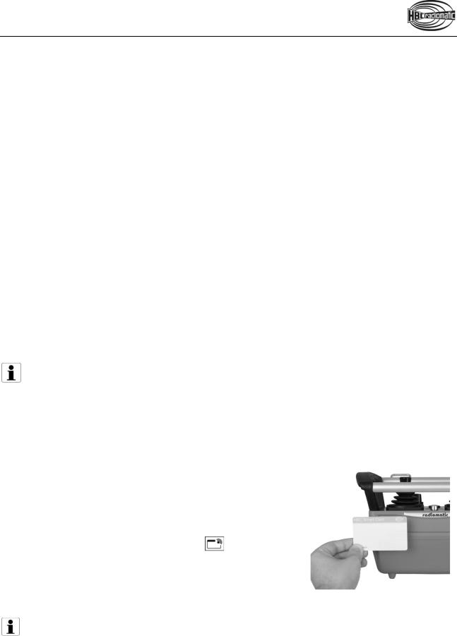
With merlin® TUC
1.Insert a charged battery into the battery compartment.
2.Turn the STOP switch to unlock.
3.Press the start button.
The status LED flashes green 2 times and red 1 time per second.
4.Hold the merlin® TUC to the position
on the transmitter marked with this symbol (cf. illustration). The transmitter vibrates and an acoustic signal sounds.
When the status LED flashes green, the transmitter is ready to operate.
5.Depending on the application, you must actuate the start button again before movement commands can be carried out.
Note:
The transmitter can only be activated with a valid merlin® TUC. If you use a card that does not match the respective transmitter or is not approved for this transmitter, the transmitter vibrates 3 times. At the same time an acoustic signal sounds. The transmitter is automatically shut down after 2 seconds.
Please contact your superior in such cases.
The transmitter also shuts down if the start sequence is not completed ithinw 10 seconds. In this case press the start button and repeat the procedure!
5 / 23

Caution:
Before starting work always trigger the acoustic signal. This warns all colleagues that the machine is about to move.
Deactivating the Transmitter
Press the STOP switch.
Note:
Replace the battery when the battery display illuminates red, an acoustic signal sounds, the status LED flashes red and the transmitter vibrates (option). Otherwise, the transmitter will switch off in a few minutes.
Recharge the empty battery in the respective charger.
Automatic Power Off (APO) Function
The transmitter i s equ ipped w ith an a utomatic power off ( APO) fu nction an d w ill autom atically s hut off approx. 15 min after the last command input.
The automatic power off serves to increase safety and also saves battery power.
After an automatic power off, the transmitter must be reactivated as described in the chapter “Operation”.
Caution:
The automatic power off does not relieve the operator of the responsibility to turn off the transmitter with the STOP switch when not in use.
6 / 23
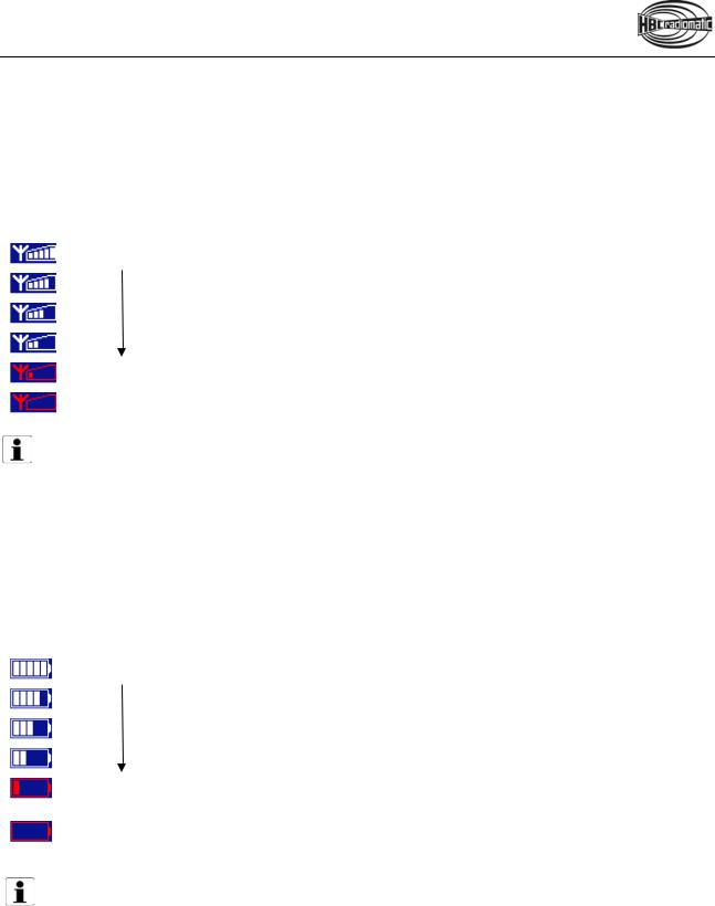
Display
Field strength
The fi eld s trength i ndication p rovides i nformation abo ut the q uality of t he r adio connecti.With an optimum c onnection, all 5 bar s ar e d isplayed. The fi eld s trength i ndication i s al ways v isible w hen the transmitter is turned on.
Field strength is indicated in the following degrees:
Strong received signal
Weak received signal
No signal
Note:
If  symbol is displayed the risk of the radio connection being interrupted is imminent. Ensure that the radio connection is not impaired by an obstacle (e.g. a building) andensure that you are within the range of the radio system. It may be necessary to change the working position.
Battery
The battery indication provides information about the current condition of the battery. It is always visible when the transmitter is turned on.
The battery status is displayed in the following degrees:
The battery is charged.
Pre-warning: The battery needs to be charged soon.
The battery needs to be charged. The status LED in the transmitter flashes red and an acoustic signal sounds. Exchange the battery. Otherwise, the transmitter will switch off in a few minutes. Recharge the empty battery in the respective charger.
Note:
A detailed description of the display has to be part of the operating manual of the specific machine in use. All instructions the operator has to follow in connection with the feedback information have to be written there as well.
7 / 23
Loading...