


Operating Instructions
Original Operating Instructions
micron 7
AOM70U00

Table of Contents
Safety Instructions
Intended Use
Safety Instructions for Installation and Operation FCC notes
IC notes
Operation
Activating the Transmitter Deactivating the Transmitter Automatic Switch-OFF (APO Function)
Display
Status Display
Individual display settings
Battery and Battery Charger
Charging the battery
Options
Safety Features Frequency Management Catch-Release
Tandem Operation Catch-Release-Tandem Operation Cable Control
radiomatic® masterkey
Address Changeover via Coding Plug
Utilization of Button  as Shift Key
Enabling of the Proportional Outputs Rotary Switch for Preselected Speed Slewing Gear Release
Feedback by LED RF-amplifier
Pre-selection of Trolley or Hoist Transmitter Key up
Technical Data Dimensions Troubleshooting Maintenance
Attachments: Return delivery note, system specific views, circuit diagrams and /or output wiring
Pictographs
Danger due to electrical voltage. Touching live parts inside the unit can be fatal or cause serious injuries.
Instructions for occupational health and safety. Not following these instructions can cause accidents, which can cause damage, serious injuries or even death.
Important information about the operation of the radio system
Manufacturer:
HBC-radiomatic GmbH • Haller Straße 45 – 53 • 74564 Crailsheim • Germany • Tel. +49 7951 393-0 • info@radiomatic.com. HBC.radiomatic GmbH is not liable for any misprints or errors! – Specifications and design subject to change without notice. ® radiomatic and radiobus are registered German trademarks.
© 07 / 2011, HBC-radiomatic GmbH, 74564 Crailsheim, Germany
No part of this document may be reproduced in any manner whatsoever without the expressed written permission of HBC-radiomatic GmbH.

Safety Instructions
Read through these operating instructions carefully before working with the radio system. This applies in particular to the installation, commissioning and maintenance of the radio system.
The operating instructions are a constituent part of the radio control system and must always be kept close at hand for the responsible personnel.
The term ‘machine’ is used in the operating instructions for the different possible uses of the radio system.
Intended Use
The radio system serves to control machines and for data transfer. Observe the job safety and accident prevention regulations applicable to each application.
The intended use also includes reading the operating instructions and adhering to all safety information contained therein.
The radio system must not be used in areas where there is a risk of explosion, nor for the control of machines used to convey persons, unless it is explicitly approved by the manufacturer for these uses.
Modifications to the radio system may only be carried out by specialist personnel who have been trained and authorized by HBC-radiomatic. All modifications must be documented at the factory in the radio control master file.
The radio control system safety devices must not be modified, removed or bypassed. In particular, modifications to any part of the radio system's complete emergency-stop system are impermissible.
Safety Instructions for Installation and Operation
The electrical connection per the accompanying output wiring diagram must be established by a qualified electrician exclusively.
The receiver may only be opened by trained personnel. Components inside the receiver can be energized at life-threatening voltages. The supply voltage for the machine must be deactivated before the receiver is opened.
Please also note with radio systems, that the presence of persons in the danger zone - in particular beneath the load (cranes!) - is prohibited in every instance.
Select a safe location for radio control, from which you have a good and complete view of the working movements of the machine, the load movements and the surrounding working conditions.
It is not permissible to put a radio transmitter unattended to one side whilst activated. Always switch the radio transmitter off when it is not required. This applies in particular if you change location, when working without radio control, during breaks and at the end of work. Always safeguard the radio transmitter against use by unauthorized persons, for example by locking it away.
In the event of an emergency and with all faults, switch the radio transmitter off immediately by pressing the STOP switch.
Only operate the radio system when it is in perfect working order. Faults and defects that could influence safety must be rectified before the system is put back into operation, by specialists who have been trained and authorized by HBC-radiomatic.
Note that the operational directions of the operating elements may appear inverted depending on location and viewing angle to the machine. This applies in particular to rotary cranes, if your location changes from inside to outside the radius of the crane. The operator must make himself familiar with the directional markings on the machine before the start of work.
Repairs may only be carried out by specialist personnel who have been trained and authorized by HBC-radiomatic. Use original replacement parts and accessories (e.g. rechargeable batteries) exclusively; otherwise it is possible that the equipment safety can no longer be guaranteed and our extended warranty will be voided.
Remain vigilant when working with the radio system and familiarize yourself with its functions. This applies in particular if you are working with it for the first time or if you work with it only occasionally.
Check each time before starting work the function of the STOP switch.
When you press the STOP switch with the transmitter on, the status LED and the display of the transmitter have to go out. If the status LED and the display don’t go out then you have to disable
the radio control system immediately.
Remove the battery and the radiomatic® iLOG from the transmitter and inform a service technician.

FCC notes
Part 15.21 Statement
Changes or modifications made to this equipment not expressly approved by HBC-radiomatic GmbH may void the FCC authorization to operate this equipment.
Part 15.105 Statement
This equipment has been tested and found to comply with the limits for a Class B digital device, pursuant to Part 15 of the FCC Rules. These limits are designed to provide reasonable protection against harmful interference in a residential installation. This equipment generates, uses and can radiate radio frequency energy and, if not installed and used in accordance with the instructions, may cause harmful interference will not occur in a particular installation. If this equipment does cause harmful interference to radio or television reception, which can be determined by turning the equipment off and on, the user is encouraged to try to correct the interference by one or more of the following measures:
Reorient or relocate the receiving antenna.
Increase the separation between the equipment and receiver.
Connect the equipment into an outlet on a circuit different from that to which the receiver is connected.
Consult the dealer or an experienced radio/TV technician for help.
RF Exposure Statement
Radiofrequency radiation exposure information
The radiated output power of the device is far below the FCC radio frequency exposure limits. Nevertheless, the device shall be used in such a manner that the potential for human contact during normal operation is minimized.
IC notes
RSS-GEN – User Manual Statements (English/French)
Licence exempt
This device complies with Part 15 of the FCC Rules and Industry Canada licence-exempt RSS standard(s). Operation is subject to the following two conditions:
1.this device may not cause interference, and
2.this device must accept any interference received, including interference that may cause undesired operation of the device.
Le présent appareil est conforme aux CNR d'Industrie Canada applicables aux appareils radio exempts de licence. L'exploitation est autorisée aux deux conditions suivantes:
1.l'appareil ne doit pas produire de brouillage, et
2.l'utilisateur de l'appareil doit accepter tout brouillage radioélectrique subi, même si le brouillage est susceptible d'en compromettre le fonctionnement.

Operation
The transmitter is equipped with an electronic radiomatic® iLOG key. radiomatic® iLOG contains all the data required for operating the transmitter. Operation is not possible without radiomatic® iLOG!
Depending on the version the radiomatic® iLOG can also be used for operation of replacement transmitters of identical construction.
When activating the transmitter and if the radio connection is interrupted (e. g. if the connection is lost or the transmission range is exceeded), the transmitter reacts with the so-called enforced zero-position.
Release all operating elements so they can return to the zero-position and actuate the Start-button. The machine will not react if the operating elements are not in zero-position. This prevents uncontrolled machine movements after the radio connection has been interrupted.
Activating the Transmitter
With standard start sequence
Insert a charged battery into the battery compartment.
The following steps need to be carried out within 4 seconds:
1.Pull the STOP switch. ENTER START-SEQ is now shown in the display.
2.Press the  button for a short time. The
  symbol appears in the display. Release the button. The transmitter will switch off if the button is pressed for longer than half a second!
3.Press the  button again. The
  symbol appears in the display. Keep the button pressed until the status LED flashes green. Then release the button.
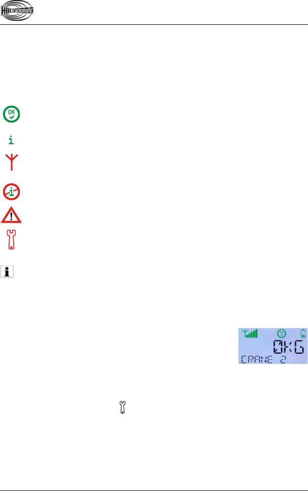
4.The symbols 

 and two text lines appear in the display. The transmitter is now ready for operation.
Note:
The transmitter switches off when
STOP switchStart buttonStatus LED
radiomatic® iLOG
Example
the  button is pressed for longer than half a second in step 2 of the start sequence.
the start sequence is not completed within 4 seconds.
another button is pressed during the start sequence.
In such cases, press the STOP switch and repeat the entire start sequence!

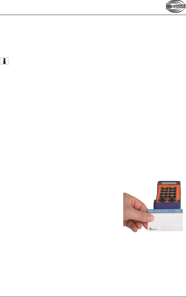
With HBC Smart Card
1.Insert a charged battery into the battery compartment.
2.Pull the STOP switch. APPLY SMART CARD is now shown in the display.
3.Hold your HBC Smart Card to the lower end of the transmitter (cf. illustration).
4.The status LED flashes green.
The following symbols are now shown in the display:


5.The transmitter is now ready for operation.
6.HELLO USER _ is shown in the display for 2 seconds.
Note:
The transmitter can only be activated with a valid Smart Card. If you use a card that does not match the respective transmitter or is not approved for this transmitter, CARD INVALID appears in the display. The transmitter is automatically shut down after 2 seconds. Please contact your superior in such cases.
The transmitter also shuts down if the start sequence is not completed within 10 seconds. In this case press the STOP switch and repeat the entire start sequence!
Caution:
Before starting work always trigger the acoustic signal. This warns all colleagues that the machine is about to move.
Deactivating the Transmitter
Press the STOP switch.
Note:
Replace the battery when the battery display flashes red, an acoustic signal sounds, the status LED flashes red and the transmitter vibrates (option). Otherwise, the transmitter will switch off in a few minutes.
Recharge the empty battery in the respective charger.
Automatic Switch-OFF (APO Function)
For safety reasons we have equipped the transmitter with an automatic switch-OFF (APO function). The transmitter is automatically put out of circuit after approx. 15 minutes of non-use.
The automatic switch-OFF also saves battery power.
After an automatic switch-OFF you must reactivate the transmitter as described in chapter “Operation”.
Caution:
The automatic switch-OFF does not relieve the operator of his responsibility to turn off the transmitter with the STOP switch when not in use.

Display
|
Field strength |
|
Status Display |
|
Battery |
|
|
 Field strength (only for systems with feedback)
The field strength indication provides information about the quality of the radio connection. With a perfect connection quality, all 5 bars of the indication are displayed green. The field strength indication is always visible when the transmitter is turned on.
Field strength is indicated in the following degrees:
Perfect reception signal
Weak reception signal
Symbol flashes: Feedback failure. The transmitter is not receiving signals from the receiver.
Note:
If the field strength is displayed in red or a feedback failure is displayed, the risk of losing radio connection is imminent. In this case, ensure that the radio connection is not impaired by an obstacle (e.g. a building). Also take care that you are within the range of the radio system. It may be necessary to change the working position.
 Battery
The battery indication provides information about the current condition of the battery. It is always visible when the transmitter is turned on.
The battery status is displayed in the following degrees:
Battery charged.
Forewarning: The battery needs to be charged soon.
Warning: The battery has to be charged. About 30 minutes remain until the automated shutdown.
Feedback
The feedback function is used to transmit various information and data from the machine or the radio receiver to the radio transmitter. A number of symbols as well as two lines of text with 6 and 10 digits respectively are available for displaying feedback information.
Feedback via symbols
Symbol shines after the transmitter has been activated.
The symbol disappears if there is a feedback or interface failure, an error notification or customer-specific warning message, or if the  symbol is displayed.
Symbol shines constantly or flashes. This symbol is defined by the customer.
Symbol flashes: Feedback failure. The transmitter is not receiving signals from the receiver.
Symbol flashes: There is an interface failure.
Symbol shines constantly or flashes: Warning!
This symbol is defined by the customer.
Symbol shines constantly or flashes. This symbol is defined by the customer.
Note:
A detailed description of the displayed customer-specific feedback information has to be part of the operating manual of the specific machine in use. All instructions the operator has to follow in connection with the feedback information have to be written there as well.
Feedback via text lines
The customer’s demand determines which feedback information is to be displayed. For example, line 1 can display the payload and line 2 simultaneously the crane capacity.
If only one line is needed for feedback information, the other line can be used for status information, for example the crane number.
Error notifications
The display enables the indication of diverse error notifications that are directly connected to the radio system. If such an error occurs, the symbol is displayed.
Simultaneously one of the following texts is displayed:
ERROR |
ERROR |
ERROR |
ERROR |
ADCON |
iLOG |
KEYBOARD |
SI2COMMAND |
In case of such an error notification immediately contact the responsible service technician!
Individual display settings
The transmitter display enables the individual adjustment of the following basic settings:
Display brightness
Fixed text in line 1
Fixed text in line 2
Note:
Always perform individual settings while the battery is charged. An empty battery can lead to an automated shut-down during the setting process and to the loss of all entries up to this point.
Access
The mentioned settings are only accessible in a special settings mode. To access this mode, the transmitter first has to be deactivated via the STOP switch. Afterwards there are 2 possible procedures, according to the transmitter version.
Standard version (= without HBC Smart Card)
Perform the following steps in max. 4 seconds:
1.Press the button on the right side of the  button in the second step and keep it actuated.
2.Pull the STOP switch.
3.Press the  button momentarily and release it. If the
  button is actuated for longer than half a second, the transmitter turns off!
4.Press the  button again until the status LED flashes green.
5.MENU ADJUSTMENT is now shown in the display. Release the  button and the button on the right side. You are now in the first menu level.
Version with HBC Smart Card
Perform the following steps in max. 4 seconds:
1.Press the button on the right side of the  button in the second step and keep it actuated.
2.Pull the STOP switch. APPLY SMART CARD is now shown in the display.
3.Hold your HBC Smart Card to the lower end of the transmitter (cf. illustration).
4.The status LED flashes green. MENU is shown in the first text line, ADJUSTMENT in the second text line.
Release the button on the right side of the  button. You are now in the selection menu.

Basic functions
There are various menu levels available for entering individual settings. The level you are currently in is displayed in the first text line (= the upper line). In addition, bars appear in the left corner over the text line. The number of bars indicates the current menu level. By browsing with the navigation button, the second text line can display the respective available sub-menus or the configurable fields.
Current menu level.
Here: Level 1.
Current menu
The display navigation and the input of your settings are made via the 2-step element has two basic functions:
Selected sub-menu (further sub-menus or configurable fields can be displayed by browsing).
 button. This operating
The first step enables browsing between sub-menus or (in the last level of the menu structure) moving the cursor between the editable values and selecting the requested character. If the first step is pressed continuously, the display browses through the sub-menus until the  button is released or pressed into the second step. If you momentarily press the button once in step 1, the next sub-menu is selected.
The second step is used for menu selection and saving your settings.
All individual settings begin in the selection menu (the first text line here displays MENU). You can return to the selection menu from all levels easily. Simply press the  button in the second step for longer than 2 seconds.
In the selection menu there are 2 sub-menus, which are shown in the second text line:
Sub-menu ADJUSTMENT
Here you can adjust the display brightness and change the fixed texts in lines 1 and 2 of the display.
Sub-menu SYSTEMDATA
Here you will find information about the radio system that can be useful in a service case (e.g. fabrication number, service phone number, frequencies etc.). Individual settings are not possible!
Note:
If you want to work with the transmitter after finishing your settings, you need to deactivate the transmitter via the STOP switch and reactivate it by the standard start-up sequence or your HBC Smart Card. For safety reasons, changing directly from the settings mode to working mode is not possible.
 Loading...