


Weekly
Monthly
Quarterly
TEST |
IDEAL RANGE |
|
Free Chlorine |
1.0 - 3.0 ppm |
|
pH |
7.2 - 7.8 |
|
|
|
Alkalinity |
80 - 120 ppm |
Salt |
2700 - 3400 ppm |
Stabilizer |
60 - 80 ppm |
Calcium |
200 - 400 ppm |
Electrolytic Cell |
inspect & clean |
|
|
ADJUSTMENT REQUIRED
Raise desired output % to increase, lower desired output % to decrease -OR- increase or decrease pump filtration time.
Too high - add muriatic acid Too low - add soda ash.
Add baking soda to increase. Add acid as required to decrease.
Add salt as required to increase.
Add cyanuric acid to increase.
Add calcium to increase.
Drain and add water to decrease.
Refer to section in manual.
SmartControl
Automation
Operation Manual
for models
PL-PS-4-X288 PL-PS-8-X288 PL-PS-16-X288
620 Division St. |
092348BRevC |
www.haywardnet.com |
|
Elizabeth, NJ 07207 |
Copyright © 2010 Hayward |
||
|

IMPORTANT SAFETY INSTRUCTIONS
When using this electrical equipment, basic safety precautions should always be followed, including the following:
•READ AND FOLLOW ALL INSTRUCTIONS
• |
! |
WARNING: Disconnect all AC power during installation. |
• |
! |
WARNING: Water in excess of 100 degrees Fahrenheit may be |
|
|
hazardous to your health. |
• |
! |
WARNING: To reduce the risk of injury, do not permit children to |
|
|
use this product unless they are closely supervised at all times. |
•A green colored terminal marked “Grounding” is located inside the wiring compartment. To reduce the risk of electric shock, this terminal must be connected to the grounding means provided in the electric supply service panel with a continuous copper wire equivalent in size to the circuit conductors supplying the equipment.
•One bonding lug for US models (two for Canadian models) is provided on the external surface. To reduce the risk of electric shock, connect the local common bonding grid in the area of the swimming pool, spa, or hot tub to these terminals with an insulated or bare copper conductor not smaller than 8 AWG US / 6 AWG Canada.
•All field installed metal components such as rails, ladders, drains, or other similar hardware within 3 meters of the pool, spa or hot tub shall be bonded to the equipment grounding bus with copper conductors not smaller than 8 AWG US / 6 AWG Canada.
•SAVE THESE INSTRUCTIONS
LIMITED WARRANTY (effective 04/01/09) Hayward/Goldline warrants its Pro Logic and E-Command pool automation products as well as itsAqua Rite,Aqua Rite Pro,Aqua Plus and SwimPure chlorination products to be free of defects in materials and workmanship, under normal use and service, for a period of three (3) years. Hayward/Goldline also warrants itsAqua Trol chlorination products to be free of defects in materials and workmanship, under normal use and service for a period of one (1) year. These warranties are applicable from the initial date of installation on private residential swimming pools in the US and Canada.
Hayward/Goldline warrants all the above-identified pool automation and chlorination products installed on commercial swimming pools and on swimming pools outside of the US and Canada for a period of one (1) year. Likewise, Hayward/Goldline warrants all accessories and replacement parts for the above-identified pool automation and chlorination products for a period of one (1) year. Each of these warranties is not transferable and applies only to the original owner.
Proof of purchase is required for warranty service. If written proof of purchase is not provided, the manufacturing date code will be the sole determinant of the date of installation of the product. To obtain warranty service or repair, please contact the place of purchase or the nearest Hayward/Goldline authorized warranty service center. For more information on authorized service centers please contact the Hayward/Goldline Technical Service Support Center (61 Whitecap Road, North Kingstown RI, 02852) or visit the Goldline web site at www.goldlinecontrols.com or the Hayward website at www.haywardnet.com.
WARRANTYEXCLUSIONS:
1.Material supplied or workmanship performed by others in process of installation.
2.Damage resulting from improper installation including installation on pools larger than the product rating.
3.Problems resulting from failure to install, operate or maintain the product(s) in accordance with the recommendations contained in the owners manual(s).
4.Problems resulting from failure to maintain pool water chemistry in accordance with the recommendations in the owners manual(s).
5.Problems resulting from tampering, accident, abuse, negligence, unauthorized repairs or alternations, fire, flood, lightning, freezing, external water, degradation of natural stone used in or immediately adjacent to a pool or spa, war or acts of God.
DISCLAIMER. THE EXPRESS LIMITED WARRANTIES ABOVE CONSTITUTE THE ENTIRE WARRANTIES WITH RESPECT TO THE ABOVE-IDENTIFIED HAYWARD/GOLDLINE POOL AUTOMATIONAND CHLORINATION PRODUCTSAND IS IN LIEU OFALLOTHER WARRANTIES, EXPRESS OR IMPLIED, INCLUDING WARRANTIES OF MERCHANTABILITY OR FITNESS FOR A PARTICULAR PURPOSE. THESE WARRANTIES GIVE YOU SPECIFIC LEGAL RIGHTS, AND YOU MAYALSO HAVE OTHER RIGHTS OF EQUIPMENT, LOST PROFITS OR REVENUE, COSTS OF RENTING REPLACEMENTS, AND OTHER ADDITIONAL EXPENSES, EVEN IFTHE SELLER HAD BEENADVISED OFTHE POSSIBILITYOFSUCH DAMAGES. SOME STATES DO NOT ALLOW THE EXCLUSION OF LIMITATION OF INCIDENTAL OR CONSEQUENTIAL DAMAGES, SO THE ABOVE LIMITATION OR EXCLUSION MAY NOTAPPLY TO YOU.
NO WHOLESALER,AGENT, DEALER, CONTRACTOR OR OTHER PERSON ISAUTHORIZED TO PROVIDE, SUPPLEMENTOR MODIFYANYWARRANTYON BEHALFOFHAYWARD/GOLDLINE.
THESE WARRANTIESARE VOID IFTHE PRODUCT HAS BEENALTERED INANYWAYAFTER LEAVINGTHE FACTORY. FORTHEABOVE-IDENTIFIED CHLORINATION PRODUCTS,THESE WARRANTIESALSOARE VOID IF, DURINGTHE WARRANTYPERIOD,YOU USEAREPLACEMENT CHLORINATOR CELLOTHER THANAN UNMODIFIED, NEW HAYWARD/GOLDLINE CHLORINATOR CELL PURCHASED FROM HAYWARD/GOLDLINE. IF A WARRANTY BECOMES VOID, YOU STILL MAY PURCHASE SERVICE AND/OR TELEPHONE TECHNICAL SUPPORTAT THE THEN CURRENT TIME AND MATERIAL RATES.
48
|
Table of Contents |
|
System Overview |
Block Diagram....................................................................... |
1 |
|
Automation............................................................................. |
1 |
|
Chlorination............................................................................ |
2 |
|
Default Display...................................................................... |
2 |
Manual System |
Output Names........................................................................ |
3 |
Operation |
Filter Pump............................................................................. |
3 |
|
Lights andAux Outputs.......................................................... |
4 |
|
Pool/Spa Valves..................................................................... |
4 |
|
Heaters................................................................................... |
5 |
|
System Off............................................................................. |
5 |
|
Service................................................................................... |
5 |
Automatic System |
Using the Programming Buttons.......................................... |
6 |
Operation |
Programming Menu Flow Chart........................................... |
7 |
(Programming) |
Settings Menu........................................................................ |
8 |
|
Timers Menu.......................................................................... |
12 |
|
Group Function...................................................................... |
15 |
|
Configuration Menu............................................................... |
17 |
|
Maintenance Menu............................................................... |
32 |
Quick “How To” |
Operate the Spa - Manually.................................................. |
33 |
Guide |
Operate the Spa -Automatically.......................................... |
33 |
|
Set the Heater Temperature................................................. |
33 |
|
Set the Chlorinator Output ................................................... |
33 |
|
Start/Stop Superchlorination................................................ |
34 |
|
Program a Timeclock............................................................ |
34 |
|
Program a Countdown Timer............................................... |
34 |
|
Enter/Exit Service Mode....................................................... |
34 |
Chlorinator Operation/ |
Saturation Index..................................................................... |
35 |
Water Chemistry |
Salt Level................................................................................ |
36 |
|
Type of Salt............................................................................ |
36 |
|
How toAdd or Remove Salt................................................. |
36 |
System Maintenance |
Servicing and Cleaning the Chlorinator Cell....................... |
39 |
|
Winterizing.............................................................................. |
39 |
|
Spring Startup........................................................................ |
39 |
Troubleshooting & |
Service Mode ....................................................................... |
40 |
Diagnostic Information |
Check System Indicator........................................................ |
40 |
|
Diagnostic Menu................................................................... |
42 |
Warranty |
SmartControl Warranty.......................................................... |
48 |
47
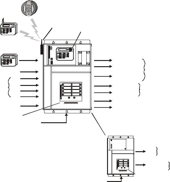
System Overview
The SmartControl is a multifunction pool controller used to fully manage your pool/spa system. The SmartControl can control pumps, valves, lighting, heaters, and chlorination. Although the SmartControl is easy to use, it is important to completely read through this operating manual before attempting to operate the control.
Optional Wireless
Spaside Remote
POOL SPA
ON OFF
ON OFF
ON OFF
ON OFF
ON OFF
|
|
Optional |
PS-4 (-8, -16) MAIN UNIT |
|
Optional Wireless |
|
Wireless Base |
|
|
|
Receiver |
Main Display |
|
|
Remote Display |
|
|
||
|
|
|
||
Keypad |
|
|
Keypad |
|
|
|
|
|
|
Optional Wired |
INPUT |
OUTPUT |
|
|
Remote Display |
|
|
Filter Pump |
|
Keypad |
|
|
|
|
(maximum of three) |
|
|
Lights |
|
|
|
|
120/240V |
|
|
External |
|
|
|
|
|
|
Relays |
|
|
Input |
|
(2 for PS-4) |
|
|
Water |
|
Aux (6 for PS-8, PS-16) |
|
Temperature |
Air |
|
Pool/Spa Suction & |
24V Valve |
Sensors |
Solar |
|
Return Valves |
|
|
|
Actuators |
||
|
|
General Purpose |
||
|
|
|
|
|
|
Spa |
|
Valves (2) |
|
|
(for dual equip) |
|
Heaters (2) |
|
Chlorinator |
|
|
||
|
|
|
||
Flow Switch |
|
Chlorinator Cell |
|
|
Circuit Breaker |
240 VAC |
|
|
|
|
Subpanel |
|
|
|
|
|
Power |
|
|
|
OUTPUT |
|
|
EXPANSION UNIT |
Aux (8) |
120/240V |
|
Relays |
|
||
|
|
|
|
(used with PS-16 only) |
|
|
|
|
General Purpose |
24V Valve |
|
|
Valves (4) |
|
Actuators |
|
Circuit Breaker |
240 VAC |
Subpanel |
Power |
|
NOTE: This manual assumes that the SmartControl has been wired and configured according to the Installation Manual. Aspects of the SmartControl that pertain to system setup are not covered in this manual.
Automation
The PL-PS-4 (-8, -16) can control up to 4 (8, 16) high voltage (120/240V) pieces of equipment, up to 4 (8 for the PS-16) automatic valve actuators, and 2 conventional heaters plus a solar heater. Both manual and automatic (programmed) operation are available. All of the control functions can be programmed at a display/keypad which is part of the main unit (typically located near the pool equipment) or at one or more remote display/keypads.
1 |
46 |
Chlorination
When the chlorinator function is enabled (requires a chlorinator cell and P-KIT sold separately), the SmartControl is also an automatic chlorine generation system for pool and/or spa sanitization. If enabled (see Configuration Menu), this operation requires a low concentration of salt (sodium chloride) in the pool/spa water. The SmartControl automatically converts the salt into free chlorine which kills bacteria and algae in the pool/spa. Chlorine will revert back to sodium chloride after killing bacteria. These reactions will continuously recycle, virtually eliminating the need to add sanitizing chemicals to your pool/spa. The only time you may need to add more salt to the pool/spa is when water is replenished due to backwashing, draining, or splashing (not evaporation).
The SmartControl is designed to handle the purification needs of most residential swimming pools up to 40,000 gallons (150,000 liters), or the needs of most commercial pools up to 25,000 gallons (95,000 liters). Check local codes for other restrictions. The actual amount of chlorination required to properly sanitize a pool varies due to bather load, rainfall, temperature, and the pool’s cleanliness.
For pools larger than 40,000 gallons, the SmartControl can control one or more SmartPure Sanitizers to supplement chlorine production.
NOTE: Before installing this product as part of a saline water purification system in a pool or spa using natural stone for coping or for immediately adjacent patios/decking, a qualified stone installation specialist should be consulted regarding the appropriate type, installation, sealant (if any) and maintenance of stone used around a saline pool with electronic chlorine generator in your particular location and circumstances.
NOTE: The use of dry acid (sodium bisulfate) to adjust pool pH is discouraged especially in arid regions where pool water is subject to excessive evaporation and is not commonly diluted with fresh water. Dry acid can cause a buildup of by-products that can damage your chlorinator cell.
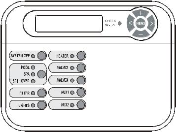
Default Display
Turn power on at the main panel and turn the SmartControl control power circuit breaker on. The keypad will show the default display. The default display alternates between the day/time, air and pool (or spa) temperature, pool/spa sanitizer setting, and salt level. Under certain circumstances, additional displays may be added to the default menu to inform you about system operation. Refer to the Programming Menu Flowchart on page 7 to view all possible displays. The SmartControl will automatically scroll through all of the available default menu displays or you can press “<” or “>” to manually scroll.
Optional Remote Display/keypad shown--the display keypad on the main control unit will have a “Service” button in the upper left corner instead of the “System Off” button.
45 |
2 |
Manual System Operation
While the main objective of the SmartControl is to automate the operation of your pool/spa system, there may be certain times when you want to override the automatic operation and control the equipment manually. To operate the pool equipment manually while keeping the automation active, perform the following procedures. Note that if you turn a relay on manually, it will remain on until either you turn it off manually, or the next time the programmed automatic operation would normally turn that relay off. Example: the filter pump is programmed to run from 9:00A to 5:00P daily. If you turn the filter pump on manually at 8:00PM, it will run continuously until the next day at 5:00PM at which time it will turn off and follow the normal program from then on. Manually turning off a relay works in a similar fashion.
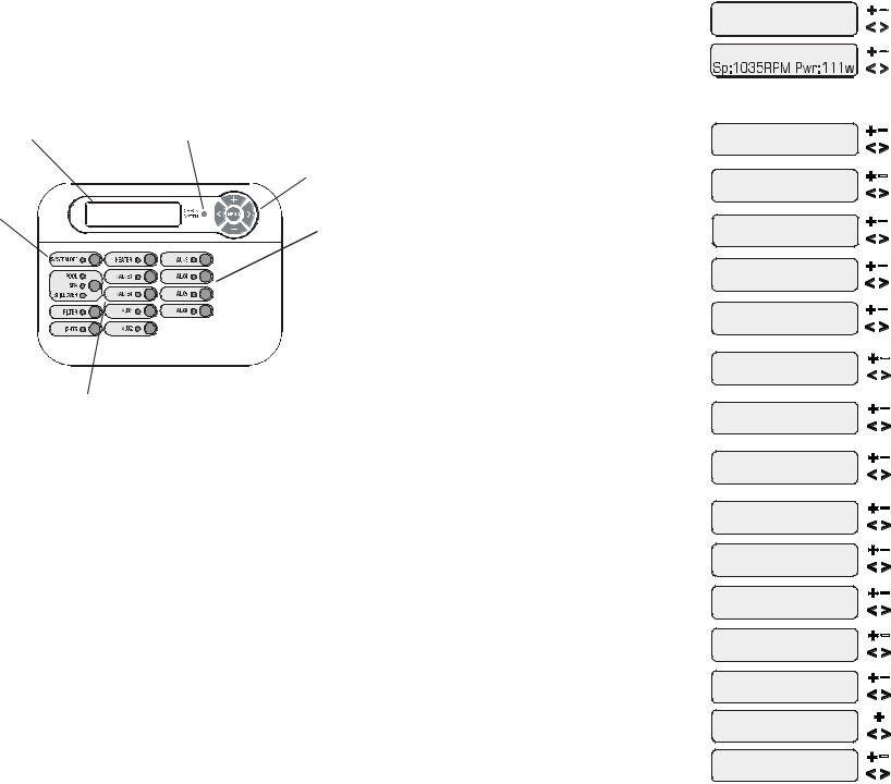
Display |
Check System LED |
|
Menu and Navigation Buttons |
System Off (remote displays) |
Aux1 - Aux6 |
or |
|
Service (main unit display) |
(On/Off) |
Valve4 or Heater2 (See Configuration Menu)
Output Names
The SmartControl is shipped from the factory with each output labeled with a generic name (e.g.AUX1, VALVE3, etc.). One of the features in the software (see Configuration Menu, page 17) is that each output can be assigned a new name that is more descriptive of the equipment being controlled. This makes it much easier to operate all of the equipment on your pool without having to memorize what each output controls. Insert name labels are also provided to be placed next to each display pushbutton. Since there is no way to know how your particular system is configured, this manual will use the original generic names for each output.
Pool Filter Pump
The pool filter pump can be manually operated whether in Standard (single pump) or Dual Equipment (separate pumps for both pool and spa) mode. When in Standard mode, the display will refer to the pool filter pump as “FILTER”. When in Dual Equipment mode, the display will read “POOL FILTER”.
Single Speed Filter Pump: If the pump is currently off, press the “FILTER” button to turn on the pump. Pressing the “FILTER” button again will turn off the pump. However, if there is a heater in the system, and it is operating, and the “Heater Cooldown” feature is enabled (Configuration Menu) then: when you press the “FILTER” button to turn off the filter, only the heater will turn off, the “FILTER” LED will flash and the display will indicate “Heater Cooldown”. At this point the filter pump will automatically turn off after 5 minutes of heater cooldown operation. If you want to override the heater cooldown, simply press the “FILTER” button again to turn off the filter pump.
If the sensor appears to operating properly, then the temperature will be displayed. If this temperature is not correct then check the placement of the sensor. If the problem is not placement related, then the sensor will, most likely, require replacement. If the display is “Open Circuit” or “Short Circuit” then check the wiring to the sensor and also make sure that the wires are secure in the terminal block in the SmartControl main unit.
if Gen 2 VSPs are detected |
Push to view the actual speed and power reported by the VSP |
VSP Speed/Power |
|
± to view |
Move to previous/next menu item |
Filter |
No function |
|
Move to previous/next menu item |
Main Software |
No function |
Revision 4.00 |
Move to previous/next menu item |
Display Software |
No function |
remote-08 r3.10 |
Move to previous/next menu item |
Exp. Unit Software |
No function |
Revision 1.10 |
Move to previous/next menu item |
Chemistry Sense |
No function |
Software r1.00 |
Move to previous/next menu item |
VSP Software |
Push to view the software revision of the connected VSPs |
± to view |
Move to previous/next menu item |
if TriStar VSPs are detected |
No function |
Pool Filter Bridge |
|
Software r1.00 |
Move to previous/next menu item |
if EcoStar VSPs are detected |
No function |
Pool Filter Display |
|
Software r1.00 |
Move to previous/next menu item |
if TriStar VSPs are detected |
No function |
Pool Filter VSC |
|
Software r1.00 |
Move to previous/next menu item |
if EcoStar VSPs are detected |
No function |
Pool Filter Drive |
|
Software r1.00 |
Move to previous/next menu item |
RF Base Software |
No function |
r1.20 ID:1234 |
Move to previous/next menu item |
6B Spa Software |
No function |
Remote A r1.00 |
Move to previous/next menu item |
Digital Spa Software |
No function |
Remote B r1.00 |
Move to previous/next menu item |
CL Module Software |
No function |
Revision 1.00 |
Move to previous/next menu item |
CL Light Software |
Press to view the software revisions of detected lights |
+ to view |
Move to previous/next menu item |
CL LT1 Software |
Press to view the software revisions of detected lights |
App:1.00 BL:1.02 |
Move to previous/next ColorLogic 4.0 light/menu item |
Available displays depend on configuration. If you call the Hayward Technical Service Dept. for assistance, they may ask for the software revisions of both the main unit and each of the display/ keypads or other devices that are attached to the system. Note that it is possible that different display/keypads have different software revision levels. For this reason, it is advisable to check this diagnostic menu item on every display.
3 |
44 |
Instant Salt
3200 PPM (+=save)
if AQL-CHEM is used
pH 7.5 |
(On) |
ORP 700 mV |
(On) |
Flow Switch
Flow
Cell Temp Sensor 77ºF
Water Sensor Open circuit
Spa Sensor Open circuit
Air Sensor 94ºF
Solar Sensor Short circuit
If a conventional or solar heater is operating, it is likely that the temperature of the water at the cell is higher than the pool/spa water temperature displayed on the SmartControl default display.
Press to load the “Instant Salt” into the averaged salt display

 Move to previous/next menu item
This display will be shown only if the chlorinator is enabled. This display shows “Instant Salt” or “Instant Minerals” (if Chlor. Config. is set for “Display Minerals”). The “Instant Salt” is calculated based on the voltage, current (amps), and water temperature at the cell. This is different than the “average salt” value which is displayed as part of the default menu. There are a number of reasons why instant and average salt readings may differ. Some of these include salt having just been added to the pool and not yet thoroughly mixed, calcium buildup on the cell, and the cell aging.

 No function

 Move to previous/next menu item
This display will be shown only if sensing is enabled. This display shows both pH and ORP levels/ status when chemistry sensing is enabled via the Chemistry Configuration Wizard (requires the use of AQL-CHEM Sensing Kit). The SmartControl will refer to these levels to determine how much chlorine to generate (ORP) and, if using an AQL-CHEM2 dispense kit, how much CO or acid to dispense (pH). Refer to theAQL-CHEM manual for specific information about these levels as2well as the recommended ranges.

 No function

 Move to previous/next menu item
This display will be shown only if the chlorinator is enabled. The current status of the flow switch is displayed. There is a short delay when transitioning from flow to no-flow and a longer delay on the transition from no-flow to flow. The delay time is displayed.

 No function
Move to previous/next menu item

 No function

 Move to previous/next menu item

 No function

 Move to previous/next menu item

 No function

 Move to previous/next menu item

 No function

 Move to previous/next menu item
NOTE: If Pool and Spa-Dual is selected, the water sensor will display as “Pool Sensor”.
Displays actual speed (in % or RPM) and power consumption (in Watts) as reported by the selected VSP.
43
Two Speed Filter Pump: If the pump is currently off, simply press the “FILTER” button to turn on high speed operationofthefilterpump. The“Filter”LEDwillilluminatecontinuously. Pressingthe“FILTER”buttonagainwill switch to low speed operation and the “FILTER” LED will flash. Note that if the pump has been off for more than 30 seconds, it will run at high speed for 3 minutes regardless of selection. This high speed operation helps allow the pump to prime and establish normal water flow.
Variable Speed Filter Pump: If the pump is currently off, press the “FILTER” button to turn the filter pump on to the last speed (1, 2, 3, or 4) that was used.Atemporary display is generated indicating the current speed selection (Filter On:Spd 1). Pushing the “+” or “-” button changes the speed selection. If the pump has been off for more than 30 seconds, it will run at the highest speed for 3 minutes regardless of selection. This high speed operation helps allow the pump to prime and establish normal water flow.
Freeze Protection: This function protects the pool, plumbing, and equipment against freeze damage. If Freeze Protection is enabled and the AIR temperature sensor falls below the preset freeze protection temperature (see Filter Configuration), the SmartControl will turn on the filter pump to circulate the water.
Spa Filter Pump (when using Dual Equipment)
Single Speed Filter Pump: If the pump is currently off, press the “AUX1” button to turn on the pump. Pressing the “AUX1” button again will turn off the pump. However, if there is a heater in the system, and it is operating, and the “Heater Cooldown” feature is enabled (Configuration Menu) then: when you press the “AUX1” button to turn off the filter, only the heater will turn off, the Filter LED will flash and the display will indicate “Heater Cooldown”. At this point the filter pump will automatically turn off after 5 minutes of heater cooldown operation. If you want to override the heater cooldown, simply press the “AUX1” button again to turn off the filter pump.
Two Speed Spa Filter Pump: If the pump is currently off, simply press the “AUX1” button to turn on high speed operationofthefilterpump. The“AUX1”LEDwillilluminatecontinuously. Pressingthe“AUX1”buttonagainwill switch to low speed operation and the “AUX1” LED will flash. Note that if the pump has been off for more than 30 seconds, it will run at high speed for 3 minutes regardless of selection. This high speed operation helps allow the pump to prime and establish normal water flow.
Variable Speed Filter Pump: If the pump is currently off, press the “AUX1” button to turn the filter pump on to the last speed (1 or 2) that was used.Atemporary display is generated indicating the current speed selection (Filter On:Spd 1). Pushing the “+” or “-” button changes the speed selection. If the pump has been off for more than 30 seconds, it will run at the highest speed for 3 minutes regardless of selection. This high speed operation helps allow the pump to prime and establish normal water flow.
Freeze Protection: This function protects the pool, plumbing, and equipment against freeze damage. If Freeze Protection is enabled and the AIR temperature sensor falls below the preset freeze protection temperature, the
SmartControl will turn on the spa filter pump to circulate the water.
Lights and Aux Outputs
Standard Relay: Manual operation of all relays (LIGHTS,AUX1 andAUX2 for a PS-4 model, LIGHTS,AUX1 -AUX6 for a PS-8 model, or LIGHTS,AUX1 -AUX14 for a PS-16 model) is identical. Assuming that the relay is currently off, simply press the appropriate button to turn on the relay. If the relay does not turn on, it probably is due to the “interlock” feature (which was set up in the Configuration Menu) being activated that requires the filter pump to be running and the valves to be in the pool-only position. This protects pumps and other equipment from possible damage. If the controlled output is on, pressing the appropriate button again will turn off the relay. Manual turn off is disabled if the “Freeze Protection” feature is enabled and the air temperature is less than the selected freeze temperature threshold.
Dimmer Relay: If Lights or an Aux output is configured as a dimmer, pressing the corresponding button will generate a temporary display which shows the dimmer output level (Off - On 100%). Pushing the “+” or “-” button changes the level in increments of 20%. When the desired output level is displayed, press the corresponding button again to turn off the display and return to normal operation. When the Lights orAux output comes on again (either manually or automatically), the dimmer output level will be the same as the last time that it was set.
ColorLogic Relay: This selection will only appear if an optional ColorLogic Network Module (AQL-COLOR- MODHV) is detected at startup. The Network Module allows the SmartControl to control custom colors and light shows in Hayward Generation 4 or later ColorLogic pool and spa lights. Refer to the AQL-COLOR- MODHV manual for details on how to configure anAux output for use with these lights. If a ColorLogic Module is detected at power up, the Lights relay is under automatic control and is used to power the ColorLogic lights.
4

VSP Relay: This selection is used to configure a Lights/Aux output to supply power and control a Hayward Variable Speed pump (VSP).
Pool/Spa Valves
Pool-only or Spa-only systems: The POOL/SPA/SPILLOVER button has no function.
Standard Pool and Spa systems without spa spillover: In pool-only mode (“POOL” LED illuminated), press the “POOL/SPA/SPILLOVER” button to switch to spa-only operation (“SPA” LED illuminated). Pressing the “POOL/SPA/SPILLOVER” button again will switch back to pool-only. Note that the filter pump will turn off while the pool/spa valves are turning.
Standard Pool and Spa systems with spa spillover: When currently in the pool-only mode (“POOL” LED illuminated), press the “POOL/SPA/SPILLOVER” button to switch to spa-only operation (“SPA” LED illuminated). Press the button again to switch to spa spillover operation (“SPILLOVER” LED illuminated). Pressing the “POOL/SPA/SPILLOVER” button again will switch back to pool-only mode. Note that the filter pump will turn off while the pool/spa valves are turning.
Dual Equipment Pool and Spa systems without spa spillover: The POOL/SPA/SPILLOVER button has no function. The “POOL” LED will always be illuminated.
Dual Equipment Pool and Spa systems with spa spillover: When currently in the separate Pool and Spa loops mode (“POOL” LED illuminated) and the Spa Filter is off, press the POOL/SPA/SPILLOVER button to switch to spa spillover operation (“SPILLOVER” LED illuminated). Press the POOL/SPA/SPILLOVER button again to return to the separate Pool and Spa loops mode of operation. Note that the Pool Filter pump will shut off while the pool/spa return valve is turning. The system will automatically switch out of spillover whenever the spa filter pump is turned on.
NOTE: For Dual Equipment Pool and Spa systems, there is no Spa Only mode.
Heaters
This description applies to Heater1 and to Heater2, if programmed (note that the function of the Valve4 button changes to Heater2 when Heater2 is enabled). Pressing the “HEATER” button causes the SmartControl to switch the heater control output between a “forced off” state and a normal, automatic thermostatic control operating state.
System Off
Each remote display/keypad has a red “SYSTEM OFF” button on the upper left corner of the keypad. Pressing this button will turn all outputs off and they will remain off, regardless of any programmed control logic, until either the “SYSTEM OFF” button (on any remote display/keypad) is pressed again or the “SERVICE” button is pressed on the display/keypad at the main unit. The red “SYSTEM OFF” LED will illuminate to indicate that all outputs and
being forced off.
! WARNING: pressing the “SYSTEM OFF” button overrides any programmed freeze protection and may cause damage to your system in freezing conditions.
Service
The main unit keypad has a “SERVICE” key. This button is used primarily during servicing of the pool equipment. If you want to completely disable the automatic operation and operate the system manually, you can put the system into Service or Service-Timed mode by pressing the “SERVICE” button. Pressing the “SERVICE” button once will switch the system into service mode which means that all automatic functions are disabled, and the remote display/keypads are disabled (except for manual turn off for emergencies). The red “SERVICE” LED will be illuminated and the SmartControl will remain in this mode of operation until manually taken out of service mode.
Pressing the “SERVICE” button again will cause the SmartControl to switch to service-timed mode which is very similar to service mode, except that the SmartControl will automatically return to normal operation after 3 hours. During service timed operation, the “SERVICE” LED will flash and the time remaining will be displayed on the remote display keypad(s).
Pressing the “SERVICE” button again, will return the SmartControl to normal (automatic) operation. SeeTroubleshooting/Diagnostic Information for more information about the service modes.
5
•pH Timeout - Check Feeder -- If the unit has been dispensing pH for more than the selected timeout without reaching the desired level. Check the chemical supply and the feeder. If both are OK, the timeout may need to be increased. Press the “+” button to reset the alarm and resume dispensing.
•pH Calibration Error -- When using the pH Calibration Wizard and the entered test result was different from the measured pH level by ± 1.0 or more. The pH probe may need to be cleaned or replaced.
•ORP Probe Error -- If the CSM indicates that there is a problem with the ORP probe.
•ORP Low - Check Chlor -- If an ORP level of 350mV or less is detected. Check the chlorinator for proper operation.
•ORP High - Check Chlor -- If an ORP level of 950mV or higher is detected. Check the chlorinator for proper operation.
•ORP High - Chlor Off -- If an ORP level of 950mV or higher is detected and the chlorine feed mode is ORP Auto Sensing, the chlorinator has been turned off. Check the chlorinator for proper operation.
•ORP Timeout -Chlor Off -- If the unit has been chlorinating for more than the selected sanitizer timeout without reaching the desired level, the chlorinator has been turned off. Press the “+” button to reset the alarm and resume chlorination.
•Ambient Sensor-- If the SmartControl internal temperature sensor is either an open or short circuit.
For helpful troubleshooting information on any of these issues, go to the Diagnostic Menu and then scroll through the various items until you see the cause for the “CHECK SYSTEM” LED being illuminated.
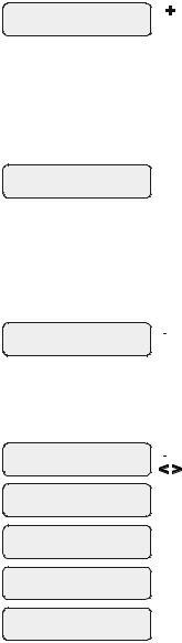
Diagnostic Menu
To enter the Diagnostic Menu, press the “Menu” button repeatedly until the display shows “Diagnostic Menu”. At this point, you can use either the “<” or “>” buttons to scroll through the various menu items which are described below:
+23.45 |
+6.75A |
Press to switch chlorinator operation to opposite polarity (15 second delay) |
84°F |
3200PPM |
Move to previous/next menu item |
+/- 23.45V is the voltage applied to the chlorinator cell +/-6.75A is the current (amps) through the cell
84ºF is the water temperature at the cell 3200PPM is the “instant” salt level at this time
This display will be shown only if the chlorinator is enabled. For the chlorinator to be operating, several other things must be happening: the filter pump must be running, the flow switch must be detecting flow, the chlorinator setting must be set greater than 0%, the water temperature at the cell must be between 50ºF and 140ºF, and the salt level must be within the operating range. If any of these conditions are not met, the chlorinator diagnostic display will tell you the reason. It’s possible to have more than one reason, in which case after you rectify what was displayed the first time, a second display will appear.
If the current (amps) display is 0.00A, then the chlorinator is operating normally but is in the off part of its normal operating cycle. Simply press either the “+” or “-“ key to start a new cycle.
The SmartControl periodically reverses the polarity of the voltage applied to the cell in order to automatically clean off any calcium deposits. It is important that you check the chlorinator operation in both polarities. To do this, press either the “+” or “-“ buttons and the chlorinator will turn off, wait for 15 seconds and then turn on in the opposite polarity.
42
 Loading...