

Hawkeye Gauge Board User Manual

► Drill with 17/64 or 9/32 bit
► Robertson Screw Driver
► Allen Key
► Tape Measure
► 7/16 wrench
► Crescent wrench
► Thread Lubricant (KOPR-
KOTE recommended)
This document provides the procedures, dimensions and parts list for the installation of a Hawkeye Industries Inc. Gauge board and Indi-
cator & Guide Kit.
Requirements
Ensure that the tank has been prepared to accept a gauge board +
Indicator & Guide kit. Refer to the Tank Preparation instructions for
details on modifying a tank to accept a Hawkeye Gauge Board.
Contents
Tools
Parts Required
A.) Gauge Board
B.) Indicator and Guide Kit
A.) Gauge Board
B.) Indicator & Guide Kit.
C.) Gauge Board with Magnetic Clips
D.) Determining # of Magnetic Clips Required
Attach the gauge board to the clips using 1/4
in. X 3/4 in. machine screws, washers and
nuts, leaving the top and bottom clips free for
installation of the indicator and guide kit. If the
indicator and guide kit is not required then se-
cure all clips with hardware as stated above.
TANK PREPARATION | GAUGE BOARD KIT INSTALLATION | FLOAT GUIDE KIT INSTALLATION | GAUGE HEAD INSTALLATION | GOSHAWK INSTALLATION
Installation Instructions
Gauge Board + Indicator & Guide Kit
Installation
QTY Part
► varies Gauge Board sections c/w decals & splices (if req)
► varies Indicator & Guide Kit
Note the order of the gauge boards by the de-
cals and connect each piece together using the
supplied splices and the 1/4 in. X 3/4 in. ma-
chine screws, nuts, and washers.
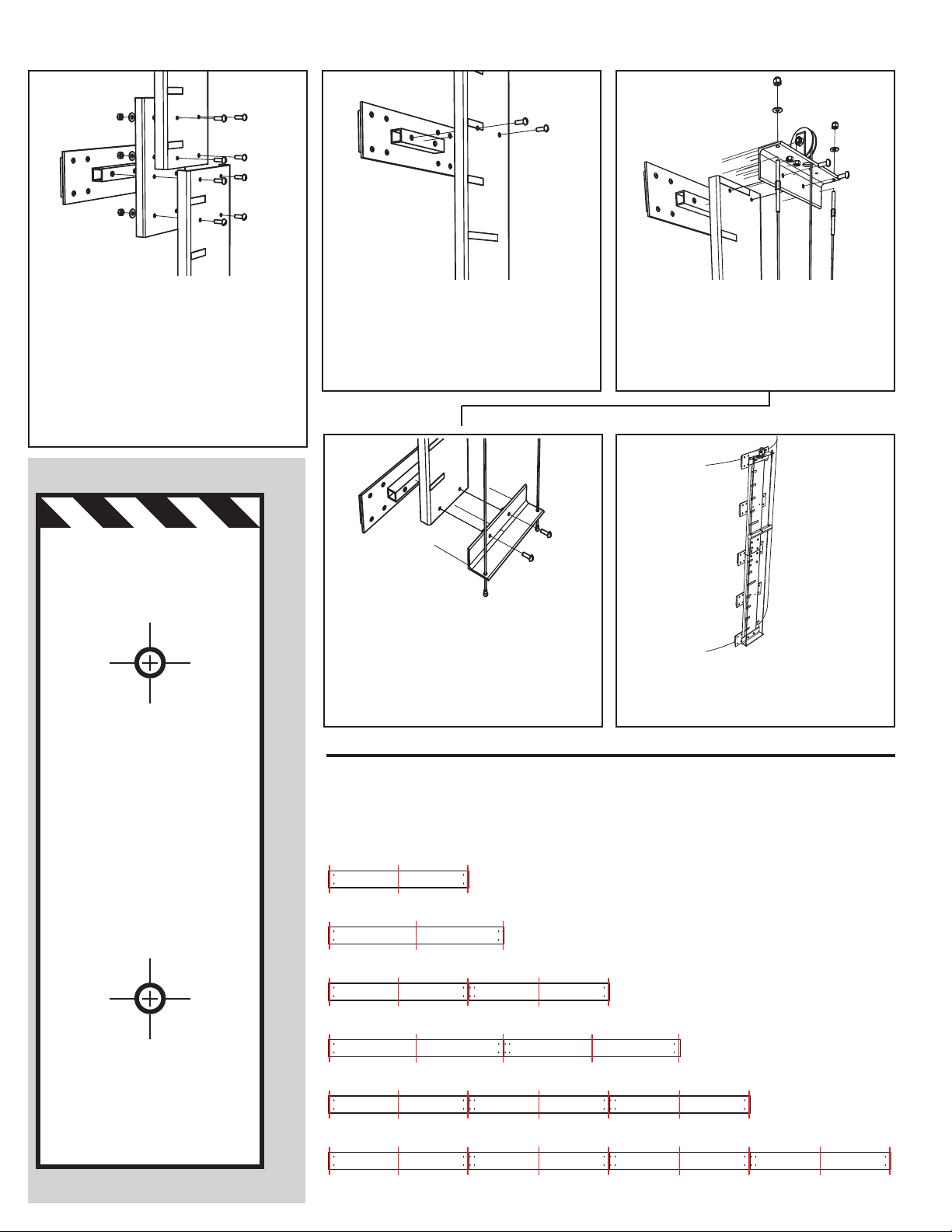
Secure the top bracket with the indicator cable
pulley to the existing holes, 0.75 in. from the
top of the gauge board and the corresponding
gauge board clip using the 1/4 in. X 3/4 in. ma-
chine screws, nuts, and washers.
Secure the bottom bracket to the existing
holes, 0.75 in. from the bottom of the gauge
board and corresponding gauge board clip
using the 1/4 in. X 3/4 in. machine screws,
nuts, and washers.
Apply KOPR-KOTE to threads and tighten both
cable studs on the top bracket until guide ca-
bles are taut.
Drill 17/64 (or 9/32) holes in the gauge board
aligned with the additional gauge board clips
that have been installed onto the tank (if re-
quired).
1.)
1.) 2.) 3.)
2.)
3.)
►
►
►
►
Gauge Board + Indicator & Guide Kit Instructions, Dec 2011
1
Note! For single-section Gauge Boards start at step 2.)
Note! When using Magnetic Gauge Board Clips, proceed to Part C.
Installation Complete. Proceed to Float Guide Kit or Gauge Head Installation
Gauge Board Installation Complete. Proceed to B.)
C.) Gauge Board & Indicator Kit with Magnetic Clips
D.) Required Number of Magnetic Clips
Note the order of the gauge boards by the de-
cals and connect each piece together using the
supplied splices and the 1/4 in. X 3/4 in. ma-
chine screws, nuts, and washers.
Omit the nuts and washers on the top pair of
bolts of the lower gauge board, and fasten di-
rectly to the magnetic gauge board clips.
At the midpoint of each gauge board section,
drill two 17/64 (or 9/32) holes, 3” apart sym-
metric about the long axis of the board.
Use the supplied template below.
►►
►
►
8 Ft Gauge Board (1x 8ft section) - 3 magnetic clips required
10 Ft Gauge Board (1x 10ft section) - 3 magnetic clips required
16 Ft Gauge Board (2x 8ft sections) - 5 magnetic clips required
20 Ft Gauge Board (2x 10ft section) - 5 magnetic clips required
24 Ft Gauge Board (3x 8ft section) - 7 magnetic clips required
32 Ft Gauge Board (4x 8ft section) - 9 magnetic clips required
Secure the top bracket with the indicator cable
pulley to the existing holes, 0.75 in. from the
top of the gauge board and the corresponding
gauge board clip using the 1/4 in. X 3/4 in. ma-
chine screws, nuts, and washers.
Secure the bottom bracket to the existing
holes, 0.75 in. from the bottom of the gauge
board and corresponding gauge board clip
using the 1/4 in. X 3/4 in. machine screws,
nuts, and washers.
Install the complete gauge board and indicator
assembly on the tank. Align and move as re-
quired to match gauge head.
The following chart outlines the minimum required number of magnetic gauge board clips recom-
mended by Hawkeye. For sizes not listed here, please consult Technical Bulletin TB-1211-GB for
calculating the required number of clips.
1.) 2.) 3.)
4.) 5.)
Installation Complete. Proceed to Float Guide Kit or Gauge Head Installation
Cut Along Solid Lines
GAUGE BOARD
ALIGN TO EDGE OF
DRILL 17/64 OR 9/32 THROUGH
2 PLACES 3.00 APART
DRILL TEMPLATE
 Loading...