

Page 1

GOSHAWK
LEVEL
TRANSMITTER
1.3.2 FILLING DIRECTION
GOSHAWK
2.3 TRANSMITTER - INTERNALS
[E] POWER TERMINAL
(ORANGE)
[F] ENCODING
POTENTIOMETER
TERMINAL (GREY)
[G] ENCODING
POTENTIOMETER
[H] PCB
[I] H-CLIP
REPLACED
BY [M] - [P]
IN GH II AND GH III
[J] OPERATOR SHAFT
[K] STANDOFFS
OPERATION AND
TROUBLESHOOTING GUIDE
Refer to www.hawk-eye.com for
latest manuals and information
READ AND UNDERSTAND THIS DOCUMENT BEFORE
INSTALLING AND USING THE GOSHAWK TRANSMITTER
REPLACES “GOSHAWK INSTALLATION INSTRUCTIONS, MAY 2010”
VALID FOR ALL GOSHAWK MODELS MANUFACTURED SINCE MID-2008.
1.0 INTRODUCTION
1.1 DESCRIPTION
The Goshawk Level Transmitter is a bolt-on, two-wire 24 VDC loop powered
transmitter that adds 4 – 20 mA electronic output to Hawkeye Industries Inc.’s Redtail
Hawk and Roadside Hawk gauge heads. The transmitter connects mechanically to the
gauge head cable reel, converting the rotational position of th e cable reel to a precise
current output.
Because Hawkeye’s Dry-Seal gauge heads use wound reels of cable as opposed to
pulleys, the rotational position of the reel provides accurate and repeatable float and
indicator position information. The solid-state nature of the transmitter electronics
allow the device to continue to track (but not transmit) float position information even
when unpowered. Powering the unit back up will provide instantaneous level position.
1.2 SAFETY CONSIDERATIONS
The Goshawk Transmitter carries CSA Hazardous Location Certification for Class I Div
1 Group C & D. Some parts of the transmitter may be classified as sparking
components, and as such the cover should only be removed from the device when in
a non-energized state, or in an non-hazardous location. Several procedures in this
manual require power to be disconnected from the transmitter before proceeding.
Failure to do so will provide erroneous calibration information, and may cause damage
to the transmitter, calibration equipment and / or process control equipment.
NOTE: INFORMATION REQUIR ED FOR SUCCESSFUL INSTALLATION
CAUTION OR IMPORTANT: INFORMATION IF NOT HEEDED MAY RESULT IN
DAMAGE TO THE EQUIPMEN T AND/OR INSTALLATION FAILURE
WARNING: INFORMATION THAT IF NOT FOLLOWED MAY RESULT IN INJURY OR
SHOCK.
1.3 ROTATIONAL ORIENTATIONS
1.3.1 EMPTYING DIRECTION
GOSHAWK
REDTAIL SYSTEM ROADSIDE SYSTEM
Indicator
moves
Float
moves
UPWARD DOWNWARD CLOCKWISE COUNTERCLOCKWISE
FIGURE 1 EMPTYING DIRECTION
Atmospheric
Reel rotates
Transmitter rotates
REDTAIL SYSTEM ROADSIDE SYSTEM
Indicator
moves
Float
moves
Atmospheric reel
rotates
DOWNWARD UPWARD COUNTERCLOCKWISE CLOCKWISE
FIGURE 2 FILLING DIRECTION
NOTE: ROTATION DIRECTIONS FOR THE GAUGE HEAD AND TRANSMITTER ARE
OPPOSITE TO ONE ANOTHER FOR THE SAME FILLING / EMPTYI NG DIRECTION IN
THE ORIENTATIONS ILLUSTRATED ABOVE. THIS IS DUE TO THE NATURAL
ORIENTATION OF EACH DEVICE THE READER WILL ENCOUNTER OVER THE
COURSE OF INSTALLING AND TROUBL ESHOOTING THE TRANSMITTER .
2.0 PART IDENTIFICATION
2.1 GAUGE HEADS
REDTAIL
GAUGE HEAD
ROADSIDE
ELECTRONIC COVER PLATE
FIGURE 3 GAUGE HEADS AND THEIR ELECTRONIC COVERS
CAUTION: THE ELECTRONIC CO VER PLATE CAN ONLY BE INSTALLED ON THE
ATMOSPHERIC SIDE OF THE GAUGE HEAD. INSTALLATION ON THE PRESSURE
SIDE WILL COMPROMISE THE GAUGE HEAD SEALS.
2.2 TRANSMITTER - EXTERNAL
ELECTRONIC COVER PLATE
GAUGE HEAD
[A] COVER
[B] COVER STAKE
SCREW
INTERNALS
SEE [E] THRU [L]
[C] BOX
[D] TRANSITION
COUPLING
ROADSIDE
REDTAIL
Transmitter
rotates
[L] OPERATOR BUSHING
[D] TRANSITION
COUPLING
2.4 TRANSMISSION (GH II AND GH III)
[M] IDLE GEAR
(LARGER)
[N] DRIVE GEAR
(SMALLER)
[O] TRANSMISSION
[G]
CHASSIS
[P] TRANSMISSION
CENTRE AXLE
[J]
2.5 PCB
[S] R10 TRIMMER
[Q] TEST POSTS
TP3 & TP4
[R] R13 TRIMMER
[E] [F]
[U] R19 (SPAN)
TRIMMER
[H]
3.0 BASIC INSTALLATION
NOTE: BEFORE STARTING INSTALLATION, READ AND UNDERSTAND ALL THE
INSTRUCTIONS PROVIDED BELOW.
3.1 TOOLS REQUIRED
Transmitter Installation
Redtail
Wrenches ............................................................ 7 / 16 in and 9 / 16 in
Pliers ....................................................Vise-grip style locking pliers
Roadside
Wrenches .............................................................. 7 / 16 in and 1 / 2 in
Pliers ....................................................Vise-grip style locking pliers
Electrical Connections & Calibration
Allen Key ................................................................................. 7 / 64 in
Screw Driver ........................................................... 1 / 8 in wide Slot Driver
Loop Calibrator ...................................................................... Fluke 789 or Eq.
Or: Multimeter ...................................................... Fluke 187 or Eq.
and Power Supply ....................................................... 13 – 24 VDC
and Load Resistance ........................................................... see 7.3
[T] TEST POSTS
TP1 & TP2
[V] R20 (ZERO)
TRIMMER
GOSHAWK INSTALLATION, OPERATION AND TROUBLESHOOTING MANUAL. 1
Page 2

Hawkeye Industries Inc. 1-800-910-4295 www.hawk-eye.com
3.2 PARTS REQUIRED
1 ea. ......................... Electronic Cover Plate (if not factory-equipped)
1 ea. ................................................ Goshawk Transmitter (included)
2 ea. ........................... 1/4 -20 UNC x 3/4 Hex Cap Screw (included)
and ........................... Existing Loop Power Process Controller / PLC
26.) Connect the (+ V) lead from the power supply to the (+) PCB Terminal [E]
27.) Connect the Red (mA) lead from the multimeter to the
(-) PCB Terminal [E].
28.) Connect the Black (COM) lead from the multimeter to the (-) or (GND)
Terminal of the DC Power Supply through your Load Resistance.
29.) Continue to Section 3.5 using the multimeter display to calibrate the
transmitter. Be sure to connect your process controller following calibrations.
3.3 INSTALLING ON THE GAUGE HEAD
3.3.1 CONFIRM GAUGE HEAD ORIENTATION AND
OPERATION
Before installing the Goshawk Transmitter, it is imperative that the gauge head is
installed correctly. Refer to the gauge head installation instructions and the direction
diagrams in Section 1.3, noting:
Redtail: Facing the gauge board, the indicator cable will be exiting from the front, right
half of the Gauge Head (Atmospheric Side).
Roadside:. Facing the gauge board, the indicator cable will be exiting from the
underside of the left half of the Gauge Head (Atmospheric Side).
Do not proceed with Goshawk Installation until the gauge head resemble the figures in
Section 1.3.
3.3.2 REMOVE STANDARD COVER PLATE (IF REQUIRED)
If the gauge head has been shipped from the factory already prepared for transmitter
installation, the electronic cover plate will already be installed on the atmospheric side
of the gauge head. If this is the case, skip to Section 3.3.3 to zero out the float and
indicator.
1.) Using the 9 / 16 Wrench (Redtail) or 1 / 2 Wrench (Roadside), remove the
three retaining bolts holding the standard cover in place. Keep these bolts.
2.) Remove the standard cover, and set aside. You will no longer require this
cover plate for this installation.
3.) Place the Electronic Cover Plate on the Atmospheric Side of the gauge head,
and align the three mounting tangs to the bosses on the gauge head.
4.) Replace the 3 retaining bolts, and tighten wrench-tight.
TO STOP
FIGURE 6 PREPARING TRANSMITTER
CAUTION: THE GAUGE HEAD REELS CAN GENERATE CONSIDERABLE ROTATING
INERTIA IF EXCESSIVE FO RCE IS USED TO MANUALLY MOVE THE F LOATINDICATOR SYSTEM. THIS INERTIA CAN EASILY OVERTURN THE ENCODING
POTENTIOMETER, AS WELL A S INTRODUCE SLACK INTO THE FLOAT A ND
INDICATOR CABLES, LEADI NG TO TANGLES OR BINDING I NSIDE THE GAUGE HEAD.
FOR THIS REASON, IT IS STRONGLY RECOMMENDED THAT NO ROPE OR OTHER
MEANS OF MOVING THE INDI CATOR FROM THE GROUND BE USE D WITH A DRYSEAL GAUGE HEAD -- WITH OR WITHOUT -- A GOSHAWK TRANSMITTER.
[STEP 8.) AND 9.)]
3.3.5 MOUNT TRANSMITTER
10.) Place the Transmitter on the Electronic Cover Plate, ensuring th e
TRANSITION COUPLER [D] mates with the gauge head axle without binding.
11.) Align the mounting tangs on the Goshawk Box [C] to the tapped holes on the
Electronic Cover Plate. Partially thread in the included 1 / 4 UNC x 3 / 4 Hex
Cap Screws to hold the transmitter in place.
12.) If the reel was secured in Section 3.3.2 release the vise grips.
13.) Gently rotate the reel in the Filling Direction (COUNTERCLOCKWISE). Ensure
that the reel is able to rotate freely, and does not bind against the transition
coupling. If there is some binding, allow the transmitter to self-centre on the
cover over the course of a few rotations.
14.) Once running smoothly, replace the vise grips (again, if the zero point is not
at the bottom of the tank) and tighten the 1 / 4 UNC x 3 / 4 Hex Cap Screws
the rest of the way to secure the transmitter to the gauge head.
1/2 TURN
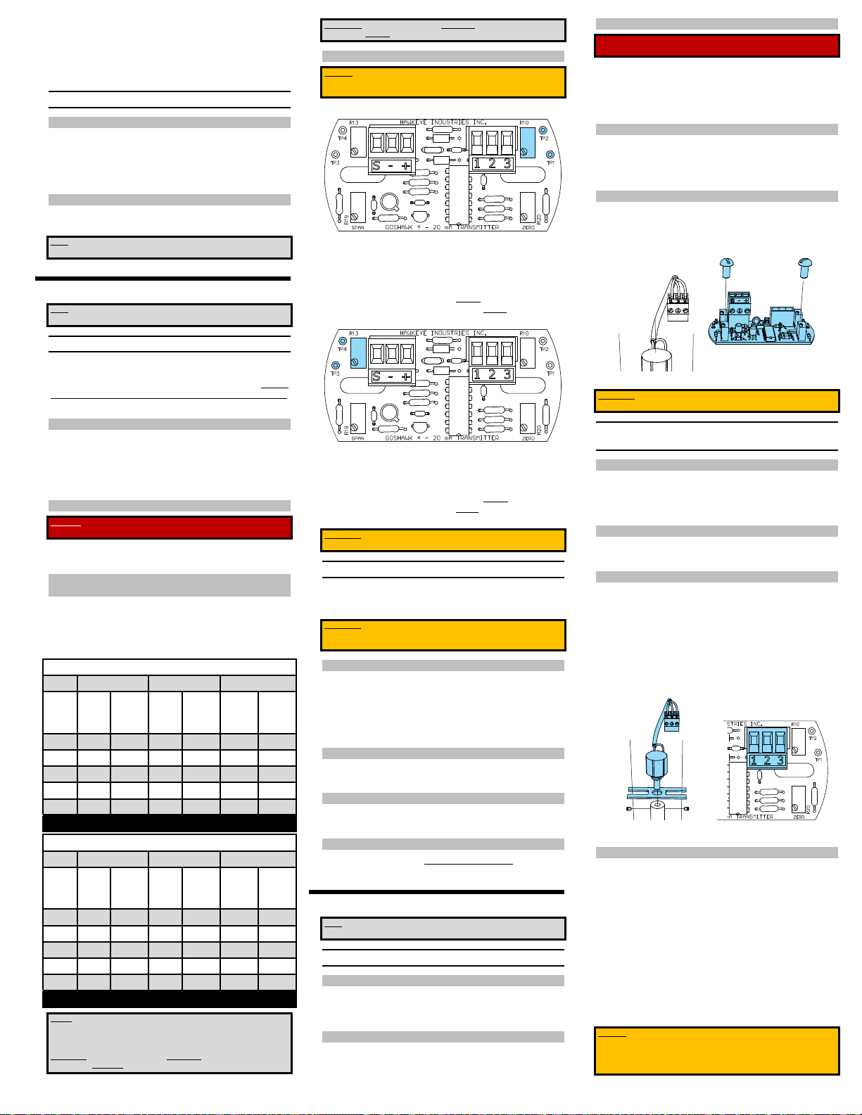
FIGURE 8 PCB POWER CONNECTIONS. [STEP 17.) TO 29.)]
3.5 CALIBRATION
3.5.1 SET ZERO
NOTE: IF YOU ARE UNABLE TO SE T THE TANK TO THE ZERO CONDI TION BECAUSE
IT IS PARTIALLY FULL OR IN SERVICE, REFER TO SECTION 4.2 FOR NON-EMPTY
ZERO POINT SETTING.
30.) With all the gauge components free to rotate, move the indicator and float to
the TANK EMPTY POSITION, if not there already.
31.) Locate the R20 (ZERO) trimmer [V] on the PCB
FIGURE 9 ZERO TRIMMER [STEP 30.) TO 33.)]
32.) Power up the transmitter, and note the output current on your calibration
device.
33.) Adjust R20 (ZERO) [V] until output current to read 4 mA.
FIGURE 4 REDTAIL SHOWN, SAME PROCESS FOR ROADSIDE
3.3.3 ZERO OUT FLOAT AND INDICATOR
IMPORTANT: THE FOLLOWING STEPS REQUIRE THAT THE MECHANICAL
CALIBRATION STEPS FROM THE GAUGE HEAD INSTALLATION HAVE BEEN
PERFORMED. ENSURE THAT WH EN THE FLOAT IS IN THE ZER O (EMPTY)
POSITION, THE INDICATOR I S AT THE TOP OF THE GAUGEBOARD . FAILURE TO
ENSURE THIS MAY RESULT IN DAMAGE TO THE ENCODING POTENTIOMETER.
5.) If not already there, put the system into the TANK EMPTY POSITION.
[STEP 1.) TO 4.)]
Manually rotate the exposed Atmospheric Side cable reel in the Emptying
Direction (CLOCKWISE) until the float is in the empty position (i.e. resting on
the tank floor).
FIGURE 7 MOUNTING THE TRANSMITTER TO THE GAUGE HEAD
[STEP 10.) TO 14.)]
NOTE: THE TRANSMITTER’S CONDUIT C ONNECTIONS CAN EITHER BE ON TOP OF
TRANSMITTER, OR ON BOTTOM OF TRANSMITTER. SELECT THE BEST
ORIENTATION FOR YOUR APPLICATION. IT IS GENERALLY SUGGESTED THAT THE
OPEN CONDUIT CONNECTI ON EXITS AWAY FROM THE GAUGE BOARD.
3.4 MAKING POWER CONNECTIONS
3.4.1 REMOVE GOSHAWK COVER
15.) Use the 7 / 64 Allen Key to loosen the staking screw [B] on the cover [A]
16.) Unscrew the cover [A] and set down. The PCB [H] and terminal blocks will
be visible. Ensure the sealing O-Ring between the cover [A] and box [C]
remains in place.
3.4.2 MAKE POWER CONNECTIONS
Determine how you are calibrating your transmitter and go to the corresponding steps.
a.) If the indicated current is below 4 mA, turn the R20 (ZERO) trimmer
[V] CLOCKWISE until the current increases to 4 mA.
b.) If the indicated current is above 4 mA, turn the R20 (ZERO) trimmer
[V] COUNTERCLOCKWISE until the current decreases to 4 mA.
NOTE: THE MINIMUM INDICA TED CURRENT WILL BE APPROXI MATELY 3.1 – 3.2
MA. IF THE INITIAL FACTOR Y SETTING OF THE R20 TRI MMER IS FAR ENOUGH
OUT OF RANGE, THERE WILL BE VERY LITTLE CHANGE IN THE OUTPUT CURR ENT
UNTIL THE TRIMMER GETS BACK IN RANGE.
WHEN TURNING THE TRIMMER CLOCK WISE, THE OUTPUT CURRENT MAY BRIEFLY
APPEAR TO DROP AS THE ZERO TRIMMER MOVES INTO THE LINEAR
ADJUSTMENT RANGE. KEEP TURNING CLOCKWISE TO INCREASE THE OUTPUT
CURRENT.
IF ALL 23 TURNS OF THE ZERO TRIMMER HAVE BEEN TRAVERSED WITH NO
CHANGE IN THE OUTPUT CURRENT, THIS MAY BE INDICATIVE OF AN DAMAGED
ENCODING POTENTIOMETER. REPLACE THE ENCODING POTENTIOMETER PER
SECTION 5.2 AND REPEAT THE ABOVE SERIES OF STEPS.
3.5.2 SET SPAN
34.) Move the indicator to the bottom of the gauge board, which will bring the
float to the top and put the system in the TANK FULL POSITION. Prevent the
float from dropping back down by securing indicator reel to the gauge cover
using vise grip pliers.
35.) Locate the R19 (SPAN) trimmer [U] on the PCB
A.) If you are using your existing process controller or follow Steps 17.) to 20.).
B.) If you are using a Fluke 789 or eq. Process Meter, follow Steps 21.) to 24.)
FIGURE 5 DIRECTION TO ROTATE TO ZERO OUT THE FLOAT AND
6.) If, in the TANK EMPTY POSITION the float is:
7.) Secure the reel in place against the cover using the vice grip pliers to prevent
INDICATOR. LEFT: REDTAIL, GAUGE BOARD TO LEFT.
RIGHT: ROADSIDE, GAUGE BOARD TO RIGHT
(COVERS OMITTED FOR CLARITY.) [STEP 5.)]
a. NOT resting on the tank floor
(i.e. it is suspended above the floor, or the tank has an ungauged
conical bottom); or,
b. the tank is not empty, and cannot be made empty
Use the position of the indicator to set the TANK EMPTY POSITION. Rotate
the reel as indicated in Step 5.) until the indicator is at th e top of the gauge
board. In the case of the non-empty tank, this will feed some loose float
cable into the tank, so care will need to be taken to slowly take that up when
moving onto Step 34.)
the reel from turning throughout the next steps.
3.3.4 PREPARE TRANSMITTER
8.) With the bottom of the transmitter facing you, rotate the TRANSITION
COUPLER [D] in the Emptying Direction (COUNTERCLOCKWISE) until it
stops. DO NOT OVER ROTATE!
9.) Turn the TRANSITION COUPLER [D] 1/2 revolution in the Filling Direction
(CLOCKWISE). This is required, and provides a rotational buffer so the
encoding potentiometer is less likely to overturn during normal operation.
C.) If you are using a Fluke 189 or eq. Multimeter with separate DC Power
Supply, follow Steps 25.) to 29.)
A.) PROCESS CONTROLLER /PLC
17.) Connect the positive (+ 13 to +24 VDC) line from the PLC to the (+) PCB
terminal [E], and secure in place with the 1/8 slot driver
18.) Connect the negative line from the PLC to the (-) PCB terminal [E] and
secure terminal contact in place with the 1/8 slot driver.
19.) If you require a shield connection, run it to the (S) PCB ter minal [E] and
secure terminal contact in place with the 1/8 slot driver.
20.) Continue to Section 3.5, using the output from your PLC to calibrate the
transmitter.
WARNING: ENSURE THE TWO-WIRE LOOP CABLES ARE RUN OUT OF THE CONDUIT
PORT ON THE GOSHAWK BODY, OBS ERVING PROPER HAZLOC WIRI NG PRACTICES
PER CSA C22.1 SECTION 18 / APPENDIX J.
B.) PROCESS METER
21.) Ensure the leads from the process meter are connected to the correct po rts
(Red to + SOURCE, Black to – SOURCE), and the meter is set to mA Loop
Power
22.) Connect the (+ SOURCE) Lead to the (+) PCB Terminal [E]
23.) Connect the (- SOURCE) Lead to the (-) PCB Terminal [E]
24.) Continue to Section 3.5 using the Process Meter Display to calibrate the
transmitter. Be sure to connect your process controller following calibrations
C.) MULTIMETER + DC POWER SUPPLY
25.) Ensure the leads from the process meter are connected to the correct po rts
(Red to mA, Black to COM), and the meter is set to read mA.
FIGURE 10 SPAN TRIMMER [STEPS 34.) TO 37.)]
36.) Note the current output on your calibration device.
37.) Adjust R19 (SPAN) [U] until output current to read 20 mA.
a.) If the indicated current is below 20 mA, turn the R19 (SPAN)
trimmer [U] CLOCKWISE until the current increases to 20 mA.
b.) If the indicated current is above 20 mA, turn the R19 (SPAN)
trimmer [U] COUNTERCLOCKWISE until the current decreases to 20
mA.
NOTE: IF ALL 23 CLOCKWI SE TURNS OF THE SPAN TR IMMER HAVE BEEN
TRAVERSED, AND THE OUTPUT CURRENT IS STILL BELOW 20 MA, ADJUST THE
SPAN SENSITIVITY RESISTANCE DOWNWARD (SEE SECTION 4.1).
IF ALL 23 COUNTERCLOCKWISE TURNS OF THE SPAN TRIMMER HAVE BEEN
TRAVERSED, AND THE OUTPUT CURRENT IS STILL ABOVE 20 MA, ADJUST THE
SPAN SENSITIVITY RESISTANCE UPWARD (SEE SECTION 4.1).
3.5.3 CONFIRM CALIBRATION
38.) Remove the vise grips from the reel and cover so the system is free to rotate.
Gently allow the float to return to the TANK EMPTY POSITON
2 REVISION D0, MARCH 2014
Page 3
Hawkeye Industries Inc. 1-800-910-4295 www.hawk-eye.com
39.) Confirm on the calibration device that when, in the TANK EMPTY POSITION,
the current output is 4 mA. Adjust if necessary, per section 3.5.1.
40.) Gently bring the float back up to the TANK FULL POSITION. Confirm on the
calibration device that the output is 20 mA. Adjust if necessary, per section
3.5.2.
41.) If no adjustments are necessary, calibration is confirmed.
3.6 PREPARING THE GOSHAWK FOR SERVICE
3.6.1 MAKE FINAL CONNECT IONS
42.) Allow the float to return to the TANK EMPTY POSITION (zero).
43.) If external calibration equipment was used for Sections 3.4 and 3.5 (per
Section 3.4.2 B or C)
a.) power down the equipment and remove from the transmitter
b.) Follow Section 3.4.2 (A) to connect your controller.
3.6.2 CLOSE UP TRANSMITTER
44.) Replace the cover [A] on the transmitter, removed in Section 3.4.1.
45.) Use the 7 / 64 Allen key to tighten the set screw to secure the cover in plac e.
NOTE: THE GOSHAWK IS NOW FULLY INSTALLED AND READY TO BE POWERED UP
AND PUT INTO SERVICE.
4.0 ADVANCED INSTALLATION
NOTE: BEFORE STARTING INSTALLATION, READ AND UNDERSTAND ALL THE
INSTRUCTIONS PROVIDED BELOW.
DECREASING THE SPAN SENSITIVITY INCREASES THE SPAN RANGE, AND IS
ACHIEVED BY RAISING THE RESISTANCE OF THE R10 AND R13 TRIMMERS.
4.1.4 ADJUST SPAN SENSITIVITY
CAUTION: IF THE TRANSMITTER IS POWERED WHILE MEASURING R10 AND R13,
INACCURATE RESITSTANCES WILL BE MEASURED. ENSURE THE TRANSMITTER IS
DE-ENERGIZED BEFORE PROCEEDING
4.) Locate R10 [S] and Test Posts TP1 & TP2 [T].
FIGURE 11 R10, TP1 AND TP2 LOCATION [STEPS 4.) TO 8.)]
5.) Set the multimeter to read resistance (Ω)
6.) Connect the spring hook test leads to TP1 and TP2 [T]. Polarity is
unimportant.
7.) Adjust R10 [S] to the value determined in 4.1.3.
a.) Turn R10 [S] CLOCKWISE to decrease resistance.
b.) Turn R10 [S] COUNTERCLOCKWISE to increase resistance.
8.) Locate R13 [R] and Test Posts TP3 & TP4 [Q].
5.1.3 REMOVE GOSHAWK COVER
WARNING: FAILURE TO DE-ENERGIZE THE TRANSMITTER BEOFRE REMOVING THE
COVER MAY RESULT IN SH OCK OR EXPLOSION.
2.) Ensure the G oshawk is not energized.
3.) Use the 7 / 64 Allen Key to loosen the staking screw [B] on the cover [A].
4.) Unscrew the cover [A] and set down. The PCB [H] and terminal blocks
[E],[F] will be visible. Ensure the sealing O-ring between the cover [A] and
box [C] remains in place on the box.
5.1.4 REMOVE PCB
5.) Disconnect both the Orange Power terminal plug [E] and the grey Encoding
Potentiometer terminal plug [F].
6.) Remove the two Philips (or slot) screws securing the PCB to the standoffs.
Remove the PCB and set aside.
5.1.5 REASSEMBLE
7.) Remove the new PCB [H] from the ESD bag place on the standoffs.
8.) Reinstall the two Philips (or slot) screws.
9.) Reconnect the terminal plugs [E] & [F].
10.) Proceed to installation calibration, per Section 3.3 onward.
4.1 ADJUSTING SPAN SENSITIVITY
In situations where the encoding potentiometer [G] makes fewer than 9 turns to go
from the TANK EMPTY POSITION to the TANK FULL POSITION, adjusting the Span
Sensitivity can increase the precision of the R19(SPAN) trimmer [U]. In normal
circumstances, the factory default range setting of 180 Ω will be adequate to set span.
Only adjust the Span Sensitivity if you find the span range or sensitivity inadequate.
4.1.1 TOOLS REQUIRED
Electrical Connections & Calibration
Allen Key .................................................................................. 7 / 64 in
Screw Driver ........................................................... 1 / 8 in wide Slot Driver
Multimeter ...................................................................... Fluke 187 or Eq.
With: ............................................................ Spring Hook test Leads
4.1.2 REMOVE COVER
WARNING: FAILURE TO DE-ENERGIZE THE TRANSMITTER BEOFRE REMOVING THE
COVER MAY RESULT IN SH OCK OR EXPLOSION.
1.) Ensure the G oshawk is not energized.
2.) Remove the cover [A], per Section 3.4.1
4.1.3 DETERMINE REQUIRED SPAN SENSITIVITY
SETTINGS
3.) Refer to the charts below to select the resistance values from the first column
that is required for R10 and R13 based on your span range. The default R10
and R13 setting is 180 Ω. It is recommended to select the next highest
resistance for R10 and R13 for the desired sensitivity, and work downward fr
there if required.
REDTAIL HAWK SPAN RANGE
Goshawk I Goshawk II Goshawk III
R10 &
Min
Max
Min
Max
R13
(ft.)
(ft.)
(ft.)
(ft.)
Min (ft.) Max
(ft.)
(Ω)
30 4.75 19.50 7.13 29.25 11.88 48.75
70 4.75 21.00 7.13 31.50 11.88 52.50
80 4.75 22.50 7.13 33.75 11.88 56.25
110 6.25 22.50 9.38 33.75 15.63 56.25
140 6.25 24.00 9.38 36.00 15.63 60.00
180 6.25 25.50 9.38 38.25 15.63 63.75
ROADSIDE HAWK SPAN RANGE
Goshawk I Goshawk II Goshawk III
R10 &
Min
Max
Min
Max
R13
(ft.)
(ft.)
(ft.)
(ft.)
Min (ft.) Max
(ft.)
(Ω)
30 2.25 9.25 3.38 13.88 5.63 23.13
70 2.25 10.00 3.38 15.00 5.63 25.00
80 2.25 17.75 3.38 16.13 5.63 26.88
110 3.00 10.75 4.50 16.13 7.50 26.88
140 3.00 11.50 4.50 16.13 7.50 26.88
180 3.00 12.00 4.50 18.00 7.50 30.00
NOTES: THE HEIGHTS IN THE CHAR TS ABOVE DO NOT INDICATE A MEASUR EMENT
RANGE (I.E. ZERO TO SPAN), BUT THE SPAN RANGE (I.E. MINIMUM SPAN TO
MAXIMUM SPAN) THAT CAN BE SET FOR THAT PARTICULAR GAUGE HEAD AND
TRANSMITTER COMBINATION.
INCREASING THE SPAN SENSITIVITY DECREASES THE SPAN RANGE, AND IS
ACHIEVED BY LOWERING THE RESISTANCE OF THE R10 AND R13 TRIMMERS.
FIGURE 12 R13, TP3 AND TP4 LOCATION [STEPS 9.) TO 11.)]
9.) Connect the spring hook test leads to TP3 and TP4 [Q]. Polarity is
unimportant.
10.) Adjust R13 [R] to the value determined in 4.1.3.
c.) Turn R13 [R] COUNTERCLOCKWISE to decrease resistance.
a.) Turn R13 [R] CLOCKWISE to increase resistance
11.) Remove test leads, and perform calibration steps from Section 3.4 onward.
IMPORTANT: IT IS IMPERATIVE THAT R10 AND R13 ARE EQUAL BEFORE
PROCEEDING TO CALIBRATION.
4.2 NON-EMPTY ZERO POINT ESTIMATION
In situations where the Goshawk is installed and calibrated on an in -service tank where
the gauging system cannot be put into the TANK EMPTY POSITION, this procedure
allows a close estimation for calibration.
IMPORTANT: THIS METHOD IS A STOP GAP, AND DOES NOT REPLACE FULL
CALIBRATION, AS PER 3.5. THE FULL CALIBRATION FROM 3.5 SHOULD BE
PERFORMED AS SOON AS REASONABLY POSSIBLE.
4.2.1 DETERMINE CURRENT TANK FILL PERCENTAGE
1.) If not already there, allow the float to return to the liquid level by disengaging
clamps put in place following Section 3.3.5
2.) Read and record the current tank level as displayed by the external indicator,
noting display units.
3.) Divide the current level by the maximum (TANK FULL) level, in the same
units. This will be a number between 0 and 1.
4.2.2 DETERMINE NEW TARGET ZERO POINT
4.) Multiply the number from 3.) by 16 mA, and then add 4 mA to this number.
5.) Use the answer from 4.) as the target Zero Point in 3.5.1 instead of 4 mA.
4.2.3 PERFORM BALANCE OF CALIBRATION
6.) Set the span per 3.5.2.
7.) Confirm the calibration per 3.5.3.
4.2.4 NON-EMPTY TARGET ZERO FORMULA
TargetZeromA16
4
5.0 PART REPLACEMENT
NOTE: BEFORE STARTING ANY OF THESE PROCEDURES, READ AND FULLY
UNDERSTAND ALL THE INSTRUCTIONS PROVIDED BELOW.
5.1 REPLACING THE PCB
5.1.1 TOOLS REQUIRED
Allen Keys .................................................................................. 7 / 64 in
Screw Driver ......................................................... Phillips or Slot (will vary)
Wrench ................................................................................. 7 / 16 in.
5.1.2 REMOVE GOSHAWK FROM THE GAUGE HEAD
1.) Use the 7 / 16 wrench to remove the two retaining bolts holding the
transmitter to the gauge head, and pull the transmitter off of the gauge head.
FIGURE 13 REMOVING THE PCB [STEPS 5.) TO 10.)]
IMPORTANT: AFTER REPLACING THE PCB, IT IS VITAL THAT THE CALIBRATION
STEPS FROM 3.3 ONWARD ARE FOLLOWED.
5.2 REPLACING THE ENCODING
POTENTIOMETER
5.2.1 TOOLS REQUIRED
Allen Keys ................................................................................. 3 / 32 in
Screw Driver ...................................................... Phillips or Blade (will vary)
and ........................................................... 1 / 8 in wide Slot Driver
Wrench .................................................................................. 1 / 2 in.
5.2.2 REMOVE PCB
1.) Follow to Sections 5.1.2, 5.1.3 and 5.1.4 to remove the Goshawk from the
gauge head, and to remove the PCB [H].
5.2.3 REMOVE THE ENCODING POTENTIOMETER
2.) Use the 3/32 Allen key to back off the set screws securing the operator shaft
[J] to the Encoding potentiometer [G]. Keep the set screws in the shaft if
possible.
3.) Pull the Encoding Potentiometer [G] and H-Clip [I] away from the operator
shaft [J].
4.) Use the 1 / 2 wrench to undo the nut and lock washer holding the H-Clip [I]
to the Encoding Potentiometer [G].
5.) Use the blade screw driver to loosen the connections on the terminal block
[F] and set the terminal block aside for reuse.
6.) Discard the removed Encoding Potentiometer [G].
FIGURE 14 REMOVING THE POTENTIOMETE R AND POTENTIOMETER
CONNECTIONS [STEPS 2.) TO 11.)]
5.2.4 REPLACE THE ENCODING POTENTIOMETER
7.) Install the H-Clip [I] on the new Encoding Potentiometer [G].
8.) Connect the cables from the new Encoding Potentiometer [G] to the terminal
block [F], noting the following color codes:
Terminal 1 .................................................................................. WHITE
Terminal 2 .................................................................................... BLUE
Terminal 3 ............................................................................... YELLOW
9.) Reinstall the Encoding Potentiometer [G] and H-Clip [I] assembly in the
Operator Shaft [J]. Ensure the arms of the H-Clip [I] are each straddling the
standoffs [K], and the H-Clip [I] is not free to rotate.
10.) Use the 3/32 Allen Key to tighten the set screws holding the Encoding
Potentiometer [G] to the Operator Shaft [J].
11.) Replace the PCB [H] and Cover [A] following Sections 5.1.2 and 5.1.4 in
reverse.
12.) Follow from Section 3.3 onward to remount the transmitter.
CAUTION: AFTER REPLACI NG THE POTENTIOMETER , IT IS VITAL THAT TH E
PREPARATION AND MOUNTING DIRECTIONS OF SECTION 3.3 ARE FOLLOWED,
OTHERWISE DAMAGE TO THE ENC ODING POTENTIOMETER WILL OCC UR AND THIS
PROCEDURE WILL HAVE TO BE REPEATED WITH A NEW ENCODING
POTENTIOMETER.
GOSHAWK INSTALLATION, OPERATION AND TROUBLESHOOTING MANUAL. 3
Page 4
Hawkeye Industries Inc. 1-800-910-4295 www.hawk-eye.com
5.3 REPLACING THE TRANSITION COUPLER
5.3.1 TOOLS REQUIRED
Allen Keys .................................................................................. 3 / 32 in
5.3.2 REMOVE OLD TRANSITION COUPLER
1.) Follow Section 5.1.2 to remove the Goshawk from the Gauge Head
2.) Back out and remove the set screw holding the Transition Coupler [D] in
Place.
3.) Set the old Transition Coupler [D] Aside.
5.3.3 INSTALL NEW TRANSITION COUPLER
4.) Slide the new Transition Coupler [D] onto the Operator Shaft [J], ensu ring
the tapped hole for the set screw aligns with the flat on the Operator shaft [J].
5.) Reinstall the Set Screw with the 3 / 32 in Allen Key and secure the coupling
[J] to the Shaft.
6.) Follow Section 3.3 onward to reinstall the transmitter.
secure into place by with the 1/16 in Allen key. Ensure the gears [M] & [N]
are meshing and moving freely before moving on.
5.4.7 REASSEMBLE TRANSMITTER
10.) Connect the Operator Shaft [J] from Section Error! Reference source not
found. to the transmission centre axel [P], and tighten the set screws with the
3 / 32 Allen key.
11.) Drop the Operator [J] / Transmission assembly [M] – [P] down through th e
operator bushing [L], and replace the retaining ring and transition coupling
[D] from Section 5.4.4.
12.) Make sure the cable running from the Encoding Potentiometer [G] is not
rubbing or binding on the transmission chassis [O] or gears [M] – [N].
13.) Reattach the PCB [H] to the standoffs [K], from Section 5.4.5. Reconnect the
Orange Power [E] and Grey Encoding [F] Potentiometer terminal plugs.
Problem: Float and Indicator not moving at all, Goshawk not working
Exceeding Encoding
Potentiometer Travel
Convert GHI to GHII or GHIII & Replace Encoding
Reversed or Partially
Reversed Installation
Ensure Gauge Head Cables wrapped in factory
Ensure Goshawk installed on Atmospheric Side of
7.0 SPECIFICATIONS
Misaligned cable Reel: Replace reel.
Ensure the Goshawk Operating Range is appropriate
for your application. Refer to 7.4.
Potentiometer [G]
Ensure Gauge Head Installed Properly and in correct
orientation, Refer to 1.3.
standard condition. Refer to 3.3.1.
Gauge Head.
7.1 MECHANICAL INPUT:
Rotational Displacement from Gauge Head Cable Reel
Goshawk I ..................................................... 3600° Max (10 revolutions)
Goshawk II ..................................................... 5400° Max (15 revolutions)
Goshawk III ..................................................... 9000° Max (25 revolutions)
Gear Ratios:
Goshawk I .......................................................................................... 1:1
Goshawk II .......................................................................................... 3:2
Goshawk III .......................................................................................... 5:2
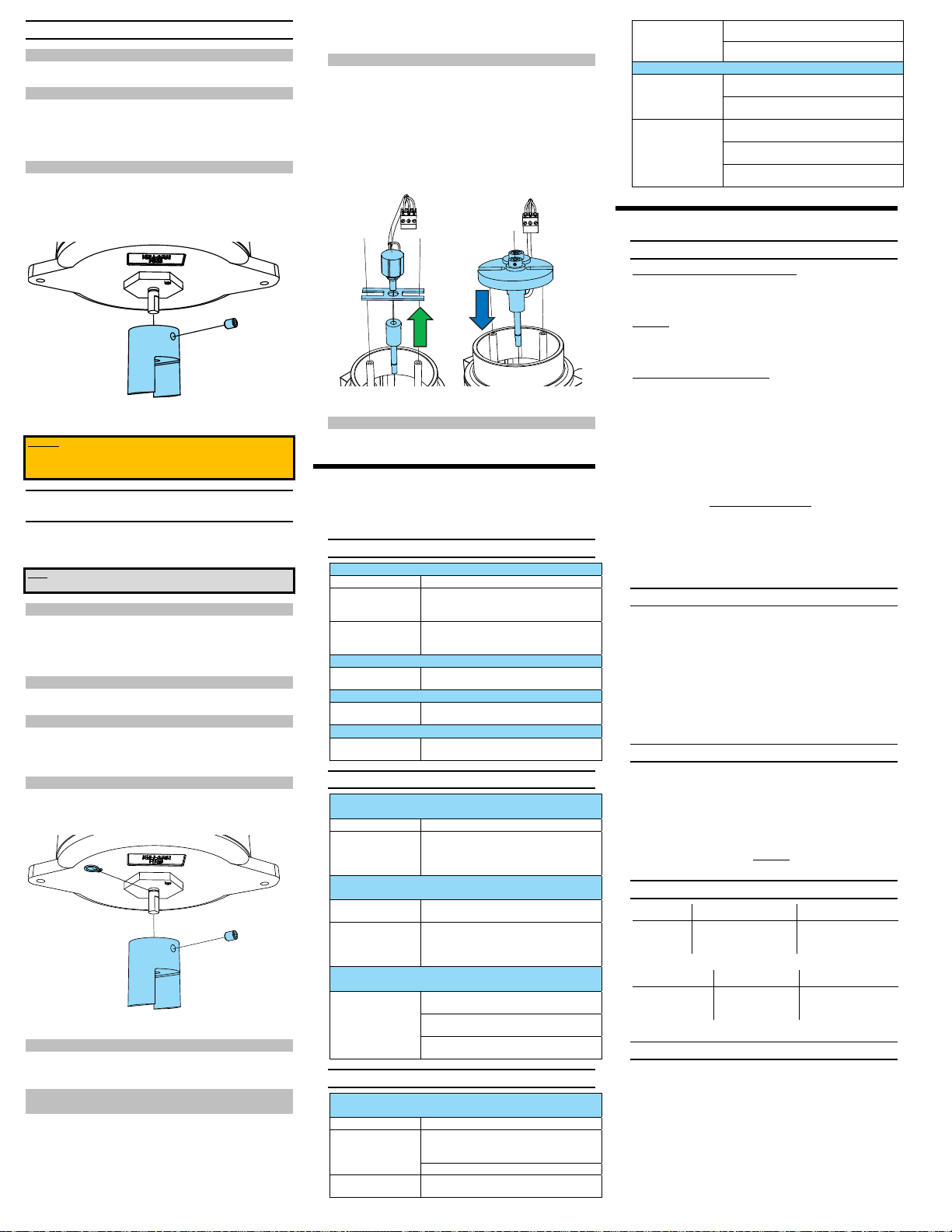
FIGURE 15 REMOVING THE TRANSITION COUPLER
[STEPS 2.) TO 6.)]
CAUTION: AFTER REPLACING THE TRANSITION COUPLER, IT IS VITAL THAT THE
PREPARATION AND MOUNTING DIRECTIONS OF SECTION 3.3 ONWARD ARE
FOLLOWED, OTHERWISE DAMAGE TO THE ENCODING POTENTIOMETER WILL
OCCUR.
5.4 INSTALLING OPTIONAL REDUCING
TRANSMISSION
To change the operating range of a Goshawk Transmitter (see 6.4) from a standard GH
I to GH II or GH III, a reducing transmission [M] – [P] can be installed after the fact.
This procedure outlines converting a GH I to a GH II or GH III.
NOTE: THIS PROCEDURE IS B EST PERFORMED WITH THE TRAN SMITTER OFF THE
TANK, AND IN A CONTROLLED, INDOOR ENVIRONMENT.
5.4.1 TOOLS REQUIRED
Allen Keys .............................................................. 1 / 16 in and 3 / 32 in
Screw Driver ....................................................... Phillips or Blade (will vary)
Wrench ..................................................................................... 1 /2 in
Retaining Ring Pliers .................................................................. ½ External Shaft
5.4.2 PARTS REQUIRED
GH II or GH III Transmission Assembly
5.4.3 REMOVE COVER
1.) Follow Section 5.1.2 to remove the transmitter from the Gauge Head.
2.) Ensure the G oshawk is not energized.
3.) Remove the cover [A], per Section 5.1.3
5.4.4 FREE THE OPERATOR SHAFT
4.) Follow Section 5.3.2
5.) Remove the 1 / 4 External Retaining Ring securing the operator sh aft [J] in
the operator bushing [L] using the retaining ring pliers.
FIGURE 16 REMOVING TRANSITION COUPLER AND FREEING
OPERATOR SHAFT [STEP 5.)]
5.4.5 REMOVE PCB & POTENTIOMETER
6.) Follow Section 5.1.4
7.) Follow Section 5.2.3
5.4.6 INSTALL POTENTIOMETER ON TRANSMISSION
CHASSIS
8.) Thread the Encoding Potentiometer [G] into underside of the transmission
chassis [O] so the Encoding Potentiometer [G] extends through the chassis
[O] and is on the same side as the small gear [N]. Refer the figure in to
Section 2.4.
9.) Use the 1/16 Allen key to back out slightly the set screw from the large gear
[M]. Slip the large gear [M], hub up, onto the potentiometer shaft [G], and
FIGURE 17 REMOVING THE HCLIP AND INSTALLING THE REDUCING
TRANSMISSION
5.4.8 INSTALL AND CALIBRATE
14.) Return to Section 3.3 and follow the installation and calibration steps.
6.0 TROUBLESHOOTING
Use the following troubleshooting steps to solve most Goshawk Transmitter problems.
If you cannot solve the problem after following this guide, call us at 1-800-910-4295
for technical support.
6.1 CALIBRATION PROBLEMS
Problem: Current does not increase beyond 3.1 mA
Symptom of Solution:
R20 (Zero) Trimmer [V]
out of operating range
Damaged Encoding
Potentiometer [G]
[ Over turned ]
Problem: Cannot get current below 4.0 mA when adjusting zero
Span Sensitivity Setting
too high
Problem: Cannot get current lower than 20 mA when adjusting span
Span Sensitivity Setting
too high
Problem: Cannot get current up to 20 mA when adjusting span
Span Sensitivity Setting
too low
6.2 NONSENSE READOUTS
Problem: Current output drops ou t to less than 4mA but resumes back
as float traverses from empty to full
Symptom of: Solution:
Damaged Encoding
Potentiometer [G]
[ Dead Spot ]
Problem: Current output increases as float moves from empty to full,
but stops changing at some midpoint between empty and full.
Insufficient input
voltage
Damaged Encoding
Potentiometer [G]
[ Dead Spot ]
Problem: Current drops as tank fills / current increases as tank
empties
Reversed Installation Ensure Gauge Head Installed Properly and in correct
Ensure Gauge Head Cables wrapped in factory
Ensure Goshawk installed on Atmospheric Side of
6.3 MECHANICAL PROBLEMS
Problem: Float and Indicator moving, Goshawk working, but
periodically getting stuck due to catching or rubbing
Symptom of: Solution:
Transmitter
Misalignment on Gauge
Head
Replace Electronic Cover Plate
Cable rubbing on gauge
head
Keep Turning R20 (Zero) [V] CLOCKWISE to increase
current output. Note, output may momentarily
decrease as the trimmer comes into operating range.
Replace Encoding Potentiometer [G], per Section
5.2.
Decrease Span Sensitivity (Increase Resistance of
R10 [S] and R13 [R]). Refer to Section 4.1.
Decrease Span Sensitivity (Increase Resistance of
R10 [S] and R13 [R]). Refer to Section 4.1.
Increase Span Sensitivity (Decrease Resistance of
R10 [S] and R13 [R]). Refer to Section 4.1.
Replace Encoding Potentiometer [G], per Section
5.2.If High agitation is a recurrent situation in your
tank, a high-agitation coupling is available to limit
wear.
Ensure the voltage, measured at the transmitter in
TANK FULL CONDITION is at least 13 VDC.
Replace Encoding Potentiometer [G], per Section
5.2.If High agitation is a recurrent situation in your
tank, a high-agitation coupling is available to limit
wear.
orientation, Refer to the figures in Section 1.3.
standard condition. Refer to Section 3.3.1.
Gauge Head.
Make sure the alignment steps in Section 3.3 have
been followed.
Ensure Gauge Head Installed Properly and in correct
orientation, Refer to Section 1.3.
4 REVISION D0, MARCH 2014
Distance Traversed per Gauge Head Rotation:
Redtail .................................................................................... 36.1 in
Roadside .................................................................................... 17.3 in
Mechanical Input Notes:
1.) The encoding potentiometer is always limited to 3600° of rotation (10
revolutions), and has hard stops at full CCW (0°) and full CW (3600°)
positions. The extended rotational displacement of the Goshawk II and
Goshawk III is achieved using an internal reducing transmission installed
between the operator shaft and encoding potentiometer.
2.) Turning the encoding potentiometer beyond its Full CCW to Full CW (0° to
3600°) range will cause irreversible damage to the internal resistive
elements, and will render the transmitter inoperable. Although the encoding
potentiometer has hard stops at the limits of its range, force and leverage
from the cable reel is often enough to overturn the encoding potentiometer.
3.) The values provided above are absolute maximums. For long life and
reliability of the Goshawk Transmitter, it is recommended that only 80% to
90% of the rotation displacement be utilized.
7.2 ELECTRICAL INPUT:
Electrical Input ........................................ 13 to 24 VDC TWO-WIRE LOOP POWER
Electrical Input Notes:
1.) 13 V is the minimum required voltage to operate the transmitter, if no other
devices are on the loop. If less than 13 V is available to the transmitter, the
output may appear to work for low current outputs, but will drop out as the
current increases.
2.) 24 V is the recommended maximum voltage to operate the transmitter.
Transients up to 40 V may be non-injurious to the electronics, but always
confirm transmitter operation following an over voltage.
3.) The Goshawk Transmitter will not work with mains or AC power.
7.3 ELECTRICAL OUTPUT:
Current output .................................................................................... 4 to 20 mA
Power Consumption: ........................................................................... 0.5 W max
Electrical Output Notes:
1.) Load Resistance (R
supply voltage (V
remains between 13 and 24 VDC through the 4- 20 mA operating range.
), including line resistance, shall be chosen such that the
L
) between the (+) and (-) terminals on the Goshawk
S
13
20
Ω
|
7.4 OPERATING RANGES
Redtail With: Absolute Height Recommended Height
GH I 8.2 m [27 ft] 7.3 m [24 ft]
GH II 12.8 m [42 ft] 11.9 m [39 ft]
GH III 21.9 m [72 ft]† 21.0 m [69 ft]†
† Goshawk range exceeds maximum gauge head range.
Roadside with: Absolute Height Recommended Height
GH I 3.7 m [12 ft] 3.4 m [11 ft]
GH II 6.1 m [20 ft] 5.5 m [18 ft]
GH III 10.4 m [34 ft]† 10.1 m [33 ft]†
† Goshawk range exceeds maximum gauge head range.
7.5 ACCURACY & ERROR
Output non-linearity: ........................................................................... 0.01% Max
Output Error: .........................0.13% Full Scale @25°C +( Gauge Error x M)
Gauge Error:
Redtail: ........................................ ± 0.06 Reel Revolutions (± 2.1 in.)
Roadside: ....................................... ± 0.07 Reel Revolutions (± 1.2 in.)
Multiplier:
Goshawk I ................................................................................ M = 1.0
Goshawk II ............................................................................... M = 1.5
Goshawk III .............................................................................. M = 2.5
 Loading...